EP1387617B1 - Kondensationsbrühtunnel für schlachttiere - Google Patents
Kondensationsbrühtunnel für schlachttiere Download PDFInfo
- Publication number
- EP1387617B1 EP1387617B1 EP02735367A EP02735367A EP1387617B1 EP 1387617 B1 EP1387617 B1 EP 1387617B1 EP 02735367 A EP02735367 A EP 02735367A EP 02735367 A EP02735367 A EP 02735367A EP 1387617 B1 EP1387617 B1 EP 1387617B1
- Authority
- EP
- European Patent Office
- Prior art keywords
- scalding tunnel
- scalding
- floor
- condensation
- tunnel according
- Prior art date
- Legal status (The legal status is an assumption and is not a legal conclusion. Google has not performed a legal analysis and makes no representation as to the accuracy of the status listed.)
- Expired - Lifetime
Links
- 241001465754 Metazoa Species 0.000 title abstract description 18
- XLYOFNOQVPJJNP-UHFFFAOYSA-N water Substances O XLYOFNOQVPJJNP-UHFFFAOYSA-N 0.000 claims abstract description 35
- 238000009833 condensation Methods 0.000 claims description 22
- 230000005494 condensation Effects 0.000 claims description 22
- 239000007788 liquid Substances 0.000 claims description 7
- 238000007664 blowing Methods 0.000 claims description 6
- 230000001105 regulatory effect Effects 0.000 claims description 4
- 230000007704 transition Effects 0.000 claims description 4
- 239000002184 metal Substances 0.000 claims description 2
- 239000008215 water for injection Substances 0.000 claims description 2
- 238000005086 pumping Methods 0.000 abstract 1
- 238000000926 separation method Methods 0.000 abstract 1
- 238000003307 slaughter Methods 0.000 description 15
- 238000000034 method Methods 0.000 description 5
- 241000282326 Felis catus Species 0.000 description 3
- 229910000831 Steel Inorganic materials 0.000 description 3
- 239000010959 steel Substances 0.000 description 3
- 206010053615 Thermal burn Diseases 0.000 description 2
- 239000002689 soil Substances 0.000 description 2
- 241000282887 Suidae Species 0.000 description 1
- 230000006978 adaptation Effects 0.000 description 1
- 238000005452 bending Methods 0.000 description 1
- 230000002308 calcification Effects 0.000 description 1
- 239000002131 composite material Substances 0.000 description 1
- 238000010276 construction Methods 0.000 description 1
- 230000008602 contraction Effects 0.000 description 1
- 230000001276 controlling effect Effects 0.000 description 1
- 230000003247 decreasing effect Effects 0.000 description 1
- 230000006866 deterioration Effects 0.000 description 1
- 238000009826 distribution Methods 0.000 description 1
- 230000000694 effects Effects 0.000 description 1
- 230000002349 favourable effect Effects 0.000 description 1
- 239000006260 foam Substances 0.000 description 1
- 210000003141 lower extremity Anatomy 0.000 description 1
- 238000004519 manufacturing process Methods 0.000 description 1
- 239000000203 mixture Substances 0.000 description 1
- 230000002250 progressing effect Effects 0.000 description 1
- 230000000630 rising effect Effects 0.000 description 1
- 239000010865 sewage Substances 0.000 description 1
- 229910001220 stainless steel Inorganic materials 0.000 description 1
- 239000010935 stainless steel Substances 0.000 description 1
- 238000003860 storage Methods 0.000 description 1
- 238000003466 welding Methods 0.000 description 1
Images


Classifications
-
- A—HUMAN NECESSITIES
- A22—BUTCHERING; MEAT TREATMENT; PROCESSING POULTRY OR FISH
- A22B—SLAUGHTERING
- A22B5/00—Accessories for use during or after slaughtering
- A22B5/08—Scalding; Scraping; Dehairing; Singeing
Definitions
- the invention is based on the object, a Kondensationsbrühtunnel the the aforementioned type with favorable for the breeder result introduction of the hot, humid air from the circulation channel in the brewing zone available do.
- the scalding tunnel according to the invention is designed so that the from the circulation channel or the circulation channels exiting, hot, moisture-laden Air in the longitudinal direction of the brewing zone distributed form from below the Brewing zone flows.
- Condensation brewing tunnels operate on the basic principle, a circulated Air flow by blowing in hot steam both moisture and to also supply heat. There is so much heat supplied to the Slaughter animals the optimal brewing temperature (usually slightly below 60 ° C) prevails. In terms of the desired temperature of the carcass the air is supersaturated with water vapor, leaving a portion of the moisture the slaughter animals (but also on the walls of the brewing zone) condensed and This results in a very intense heat transfer to the slaughter animals. The heat transfer is closer to the feeding end of the scalding tunnel naturally larger than further inside the scalding tunnel, because the freshly delivered Slaughter animals are still very significantly below the brewing temperature and therefore more water condenses on them. The auskondensierende of the slaughter animals Water runs down the slaughter animals and takes dirt from the animals Carcasses down with.
- the adjustability of the positioning of the flow guide can be on the one hand at the factory of the scalding tunnel, e.g. Vary the setting in Depending on how big the length of the scalding tunnel or the distance between several circulation channels of the scalding tunnel. She lets herself though also in the slaughterhouse after delivery of the scalding tunnel, e.g. one as good as possible adaptation to the local conditions or also to results a trial operation to accomplish. For example, in a slaughterhouse, the mostly smaller and lighter slaughter animals processed, another Setting cheaper than at another slaughterhouse.
- slaughtered animals for slaughter particularly preferred pigs in question. But you can also others Process slaughter animals that are usually brewed and in most Cases should not be skinned before later disassembly.
- the above features (d), (e) and (f) provided in the scalding tunnel for all circulation channels. But there are also cases which one can work less perfect on part of the circulation channels, e.g. dispense with the adjustability of the positioning of the flow guide can.
- the height of the flow cross section between a lower edge of the flow guide and the bottom of the floor pan changeable is.
- the said amount of Flow cross section does not have to be constant along the bottom pan (ie the lower edge of the flow guide not parallel to the floor pan got to). It is sometimes even advantageous to have this height in the longitudinal direction of the Specifically to vary the floor pan, e.g. directly opposite the exit of the Circulation channel to have a lower height than in a longitudinal direction distance from the outlet of the flow channel.
- it is the height of the flow cross section or the distance between the edge of the flow guide and the floor pan considered an average value of this height or distance.
- the flow control surface is a hood-like structure as a whole, which connects with a first longitudinal edge of the floor pan and with a second longitudinal edge spaced from the bottom of the bottom pan ends. It is particularly preferred if the flow guide in one Section of the scalding tunnel viewed transversely to its longitudinal extent, an arc-like has curved shape. "Curved" can be exact or essentially but it does not have to be circular.
- the flow guide surface preferably consists essentially of sheet metal, in particular stainless steel sheet.
- the adjustability of at least a part of the flow guide surface a screw connection (to another part of the flow guide or to a holder of the entire flow guide), which is detachable and can be tightened at different positions.
- a screw connection to another part of the flow guide or to a holder of the entire flow guide
- Other constructive alternatives are possible, e.g. clamping with spring force, both with positive detent series for discrete Positionings as well as without such.
- the bottom tray has a trapezoidal cross section with in Essentially vertical lateral boundaries and a ground leading to a Side down obliquely.
- This geometry of the floor pan leads that a particularly large free cross-section is available (the Partially for the air flow distribution over part of the length of the Floor pan can be used) and that the discharge of the condensed Brewing water from the floor pan is particularly effective and thorough play.
- the bottom of the floor pan runs to one side of the floor pan down obliquely and is at least a floor drain at the transition between the deep edge of the floor and the lateral boundary of the floor pan provided.
- This training of Soil and soil drainage result in a particularly effective and thorough Water drainage. If over the length of the floor pan several floor drains it is possible, but not mandatory, a gradient the floor of the floor pan in the longitudinal direction in each case to the respective Provide floor drain out.
- the scalding tunnel is characterized in that - in cross section Seen transversely to the longitudinal extent of the scalding tunnel - a left row and a right bank of upper cross beams extending longitudinally of the scalding tunnel are spaced, and lower cross member, in the longitudinal direction of the scalding tunnel are spaced, are provided; and that the bottom tray on the top and lower cross beams is stored.
- This skeleton of cross beams may e.g. be supported by upright supports on the bottom of the slaughterhouse. Either the cross members and possibly the supports are typically made Steel profiles.
- the scalding tunnel is preferably characterized in that for storage serving by cross beams, spaced in the longitudinal direction of the scalding tunnel Supports are provided; that - in cross section transverse to the longitudinal extent of Bending tunnels considered - left and right boundary walls of the brewing zone are provided; that the boundary walls rest at the bottom on longitudinal profiles, which are attached to the cross members; and that the boundary walls in the lower end face have a longitudinal slot in the game with one each towering edge of the floor pan engages.
- the scalding tunnel has a device for injecting liquid Water in the air stream.
- the scalding tunnel has a device for injecting liquid Water in the air stream.
- part of the total introduced water introduced in liquid form and another Part in vapor form.
- moisture and Controlling the temperature in the brewing zone more precisely.
- the scalding tunnel has means for increasing the pressure of the liquid water for injection.
- the liquid water can be in Inject very finely atomized form. In addition, you will from pressure fluctuations and local pressure differences of the public water supply network free.
- the scalding tunnel has a system for producing hot Water vapor, to which the nozzles for blowing hot steam are connected in the airflow.
- This is usually cheaper than about the supply of hot steam to the scalding tunnel from a separate Production site ago, although the latter is alternatively possible.
- the scalding tunnel preferably has a device for regulating the quantity of the water vapor injected into the air stream; particularly preferred a regulation of the amount of water vapor according to the temperature in the Brewing zone of the scalding tunnel.
- the amount of per unit time in the airflow injected water vapor is an optimal means of regulating the temperature in the brewing zone.
- Softened water leads to a better brewing result, not to mention the reduction of calcification in the Steam generating system and at the nozzles.
- the scalding tunnel has a device for swirling and centering the air flow in the brewing zone of the scalding tunnel on. This creates more uniform and intensive heat transfer conditions of the Air flow to the slaughter animals.
- the scalding tunnel 2 is assigned an upper conveyor 18.
- the conveyor 18 has a side rail 20, a series of rollers along the Longitudinal member 20 movable cats 22, each hanging a transport hook 24 on the cat in question 22, and one hanging chain 26 each on the relevant hook 24.
- At each Schlingkette 26 can with a Hind leg attached a pig 28 head down.
- the hook 24 passes through a longitudinal slot 30 in the upper limit 8, and brush-like Seals 32 seal the longitudinal slot 30 without the movement of the hook 24 along the longitudinal slot 30 to prevent.
- a powered transport chain for conveying the cat 22 along the longitudinal member 20 is not shown.
- a circulation channel 10 or - in particular at longer scalding tunnels 2 - several circulation channels 10 with mutual Be provided for a distance The same applies to the process 16, where even at shorter scalding tunnels 2 usually several processes 16 are provided and wherein the distance of the processes 16 by no means with the distance of the circulation channels 10 must match.
- the main length of the circulation channel 10 is vertical, parallel outside one the boundary walls 6. From the entrance 34 of the channel 10 is initially a piece horizontal. There then sits the blower 38. Below there is a diversion to a substantially horizontal end portion with the outlet 36 am The End.
- the described circulation channel 10 is thus mainly outside the other boundary of the scalding tunnel 2, normally on the back of the scalding tunnel 2, while in Fig. 1 to the right of the scalding tunnel 2 is usually a person walkable aisle of Slaughterhouse is located.
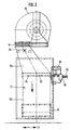
- FIG. 2 shows the structure of the frame 4.
- the frame. 4 has as the most essential components one - in the viewing direction of FIG. 2 - left row and right row of upright columns 42, a row of lower ones Crossbeams 44 and a left row and a right row of upper ones Cross beams 46 on.
- the lower cross member 44 and the upper cross member 46th are attached to the supports 42 e.g. fixed by welding.
- the supports 42, the lower cross member 44 and the upper cross member 46 are each made of steel profile produced.
- the supports 42 are at the bottom of the slaughterhouse floor 48.
- FIG. 2 can be seen particularly clearly the bottom tray 12.
- Top right and left closes respectively a nearly horizontal section 58 with a slope to the bottom tray 12, thereby the floor pan 12 (in the broader sense) is completed.
- the actual floor pan 12 is an upwardly pivotable Grating 60 with passage slots and / or through holes, the one Occupy most of its area.
- the bottom tray 12 is made of stainless Sheet steel.
- the already described outlet 36 of the circulation channel 10 extends over the entire height of the lateral boundary 50 of the floor pan 12, but could also be less high.
- the longitudinal extent of the Outlet 36 measured at right angles to Zeichnüngsebene of FIG. 2 and thus measured in the longitudinal direction of the bottom tray 12, is in the drawn Embodiment good twice as large as the height of the outlet 36, see Fig. 3, but could still be longer.
- the flow guide 14 is arranged within the trapezoidal space in the central region of the bottom trough 12th is the outlet side of the outlet 36.
- the flow guide 14 has a length, measured at right angles to the plane of the drawing 2, which is substantially equal to or larger than the in the same direction measured length of the outlet 36.
- the flow guide 14 has an upper part 14a which is stationary and a lower part 14b which is adjustable relative to the part 14a.
- the flow guide 14 has a total of substantially the shape of an approximately 110 ° circular arc, wherein the upper left edge of the flow guide 14 at the bottom trough 12 connects (concrete on the local section 58 rests and fixed) and the right-bottom edge at a distance d above the Floor 54 of the floor pan 12 ends.
- a support strut 61 which carries at a bend 62 a screw 64 with nut. through the screw 64 is the right-bottom edge of the upper part 14a of the flow guide 14 held.
- the lower part 14b of the flow guide 14 is e.g. through a slot or through an opening row by means of the screw 64th attached to the support strut 60, in a manner that several Positioning of the lower part 14b relative to the upper part 14a possible are.
- the height d is larger or smaller. The bigger the Height d is, the greater the proportion of moist air L coming out of the outlet 36 directly through the open flow cross section 66 in the right, above quasi-open part of the central region of the bottom tray 12 flows out.
- the drain 16 at a "corner” (in cross-section!) the central region of the floor pan 12 attaches, namely at the transition between the lower edge of the bottom 54 and the lateral there Limitation 52.
- This "corner” is not adjacent to the exit 36, but from the outlet 36 spaced so that the movement of the air flow L to drain of condensed brewing water on the bottom 54 in the drain 16 still supported.
- the connection of the drain 16 at the "Corner” of the floor pan 12 is designed so that water is not only down can run into the sequence 16, but also horizontally from the left to the right in the process 16 can pass.
- the drain 16 is designed as a round tube, which is connected to a sewage system.
- FIG. 2 one particularly clearly sees a preferred possibility the connection between the boundary walls 6 and the frame 4.
- Both left and right each have a longitudinal profile 68 is provided to the a series of upper cross members 46 is attached.
- the longitudinal profile 68 rests in each case the lower end region of a boundary wall 6.
- Each boundary wall 6 has in its lower end a longitudinal slot 70, in the game with a upstanding edge 72 of a portion 58 of the floor pan 12 protrudes. To this Way is a squeezing out of condensed water from the scalding tunnel. 2 prevented at this point.
- each wall 76 which the frame 4 closes to the outside.
- Each wall 76 rests at the bottom in one fixed to the bottom 48 of the slaughterhouse profile and goes up in the longitudinal profile 68 over.
- Fig. 3 can be seen a major part of the circulation channel 10 in another direction.
- a portion 10 a of the Channel 10 is connected, which, progressing from top to bottom, in Increased longitudinal direction LR of the scalding tunnel 2.
- the outlet 36th is also shown.
- a tube 80 with outlet openings (nozzles) is installed at the top of section 10a. There, liquid water is injected under pressure into the air stream L.
- a longitudinal direction LR of the scalding tunnel 2 extending tube 82 with nozzle openings 84 installed. By the Nozzle orifices 84 become hotter, pressurized steam in injected the air flow L.
- a not shown steam generator either in close association with the scalding tunnel 2 or at one of them more remote site of the slaughterhouse.
- a pipe 90 is hotter Water vapor introduced.
- a circulation separator 88 is condensed Water separated.
- the steam which has the state of saturated water vapor, supplied to the tube 82 with the nozzle openings 84.
- the metering device 86 is functionally a valve which opens and closes linearly in accordance with the temperature measured in the brewing zone 100. If there the temperature is below the set temperature, more steam is blown in, and vice versa.
- the cross-hatched components 92 and 94 are flexible connection portions in front of the blower 38 and behind the blower 38.
- Fig. 1 one can see pointed longitudinal projections 96 on the boundary walls 6, on the right boundary wall 6, two longitudinal projections 96th spaced above each other and on the left boundary wall 6, two longitudinal projections 96 spaced one above the other.
- each longitudinal projection 96 is the Underside concave-rounded executed; the upper side slopes downwards inclined to the longitudinal center plane of the brewing zone 100 out.
- Through the longitudinal projections 96 is a device for swirling and centering the air flow formed in the brewing zone of the scalding tunnel. Steer the longitudinal projections 96 in the brewing zone 100 from bottom to top flowing, steam-laden Air flow more to the center (between left and right in Fig. 1) of the brewing zone 100.
- Strömungsleitbleche 98 which is a reassurance of Influence in the inlet 34 effect.
Landscapes
- Life Sciences & Earth Sciences (AREA)
- Engineering & Computer Science (AREA)
- Food Science & Technology (AREA)
- Housing For Livestock And Birds (AREA)
- Cultivation Of Plants (AREA)
- Fodder In General (AREA)
- Feed For Specific Animals (AREA)
Description
- einen Eintritt im oberen Bereich des Brühtunnels;
- einen Austritt im unteren Bereich des Brühtunnels;
- ein zugeordnetes Gebläse zum Fördern eines Luftstroms durch den betreffenden Zirkulationskanal; und
- eine Anzahl von Düsen zum Einblasen von heißem Wasserdampf in den Luftstrom.
dass bei mindestens einem Zirkulationskanal die folgenden Merkmale vorgesehen sind:
- Fig. 1
- einen Kondensationsbrühtunnel im Querschnitt quer zur Längserstrekkung des Brühtunnels;
- Fig. 2
- den unteren Endbereich des Brühtunnels von Fig. 1 in größerem Maßstab;
- Fig. 3
- einen Teil des Brühtunnels von Fig. 1 in einer Blickrichtung des Pfeils III in Fig. 1.
- ein tragendes Gestell 4;
- aufrechte, seitliche Begrenzungswände 6;
- eine Begrenzungsdecke 8;
- einen Zirkulationskanal 10;
- eine Bodenwanne 12;
- mindestens eine Strömungsleitfläche 14;
- eine Verwirbelungs- und Zentriereinrichtung für die Luftströmung in der Brühzone;
- und mindestens einen Ablauf 16.
- einen Eintritt 34 im oberen Bereich der betreffenden Wand 6 des Brühtunnels 2;
- einen Austritt 36 in einer seitlichen Begrenzung der Bodenwanne 12;
- ein zugeordnetes Gebläse 38 zum Fördern eines Luftstroms durch den Zirkulationskanal 10;
- eine Anzahl von Düsen 84 zum Einblasen von heißem Wasserdampf in den durch den Zirkulationskanal 10 strömenden Luftstrom.
Claims (18)
- Kondensationsbrühtunnel für Schlachttiere, aufweisend:(a) eine sich in Längsrichtung (LR) des Brühtunnels (2) erstreckende Brühzone (100), längs derer zu brühende Schlachttiere (28) durch den Brühtunnel (2) gefördert werden können;(b) eine sich in Längsrichtung (LR) des Brühtunnels (2) erstreckende Bodenwanne (12), die mindestens einen Ablauf (16) für in dem Brühtunnel (2) kondensiertes Brühwasser aufweist;(c) einen Zirkulationskanal (10) oder mehrere Zirkulationskanäle (10) längs des Brühtunnels (2) mit gegenseitigem Abstand verteilt, der aufweist bzw. die jeweils aufweisen:dadurch gekennzeichnet, dass bei mindestens einem Zirkulationskanal (10) die folgenden Merkmale vorgesehen sind:einen Eintritt (34) im oberen Bereich des Brühtunnels (2);einen Austritt (36) im unteren Bereich des Brühtunnels (2);ein zugeordnetes Gebläse (38) zum Fördern eines Luftstroms (L) durch den betreffenden Zirkulationskanal (10);und eine Anzahl von Düsen (84) zum Einblasen von heißem Wasserdampf in den Luftstrom (L),(d) der Zirkulationskanal (10) mündet seitlich in die Bodenwanne (12);(e) in der Bodenwanne (12) ist eine Strömungsleitfläche (14) angeordnet, mit der sich der aus dem Zirkulationskanal (10) austretende Luftstrom (L) auf eine Länge in der Bodenwanne (12) verteilen lässt, die größer als die in Längsrichtung (LR) der Bodenwanne (12) gemessene Dimension des Zirkulationskanals (10) am Austritt (36) ist;(f) mindestens ein Teil (14b) der Strömungsleitfläche (14) ist hinsichtlich seiner Positionierung in der Bodenwanne (12) einstellbar.
- Kondensationsbrühtunnel nach Anspruch 1,
dadurch gekennzeichnet, dass bei allen Zirkulationskanälen (10) die Merkmale (d), (e) und (f) vorgesehen sind. - Kondensationsbrühtunnel nach Anspruch 1 oder 2,
dadurch gekennzeichnet, dass durch die Einstellung mindestens eines Teils (14b) der Strömungsleitfläche (14) die Höhe (d) des Strömungsquerschnitts zwischen einem unteren Rand der Strömungsleitfläche (14) und dem Boden (54) der Bodenwanne (12) änderbar ist. - Kondensationsbrühtunnel nach einem der Ansprüche 1 bis 3,
dadurch gekennzeichnet, dass die Strömungsleitfläche (14) insgesamt ein haubenartiges Gebilde ist, welches mit einem ersten Längsrand an die Bodenwanne (12) anschließt und mit einem zweiten Längsrand beabstandet von dem Boden (54) der Bodenwanne (12) endet. - Kondensationsbrühtunnel nach einem der Ansprüche 1 bis 4,
dadurch gekennzeichnet, dass die Strömungsleitfläche (14), in einem Schnitt des Brühtunnels (2) quer zu seiner Längserstreckung (LR) betrachtet, eine bogenartig gekrümmte Form hat. - Kondensationsbrühtunnel nach einem der Ansprüche 1 bis 5,
dadurch gekennzeichnet, dass die Strömungsleitfläche (14) im Wesentlichen aus Blech besteht. - Kondensationsbrühtunnel nach einem der Ansprüche 1 bis 6,
dadurch gekennzeichnet, dass zur Einstellbarkeit mindestens eines Teils (14b) der Strömungsleitfläche (14) eine Schraubverbindung (64) vorgesehen ist, die lösbar ist und bei unterschiedlichen Positionierungen festziehbar ist. - Kondensationsbrühtunnel nach einem der Ansprüche 1 bis 7,
dadurch gekennzeichnet, dass die Bodenwanne (12) einen trapezförmigen Querschnitt hat mit im Wesentlichen vertikalen seitlichen Begrenzungen (50, 52) und einem Boden (54), der zu einer Seite hin schräg abwärts verläuft. - Kondensationsbrühtunnel nach einem der Ansprüche 1 bis 8,
dadurch gekennzeichnet, dass - im Querschnitt betrachtet - der Boden (54) der Bodenwanne (12) zu einer Seite der Bodenwanne (12) hin schräg abwärts verläuft und dass mindestens ein Bodenablauf (16) am Übergang zwischen dem tiefen Rand des Bodens (54) und der seitlichen Begrenzung (52) der Bodenwanne (12) vorgesehen ist. - Kondensationsbrühtunnel nach einem der Ansprüche 1 bis 9,
dadurch gekennzeichnet, dass eine linke Reihe und eine rechte Reihe oberer Querträger (46), die in Längsrichtung (LR) des Brühtunnels (2) beabstandet sind, und untere Querträger (44), die in Längsrichtung (LR) des Brühtunnels (2) beabstandet sind, vorgesehen sind; und dass die Bodenwanne (12) auf den oberen und unteren Querträgern (46,44) gelagert ist. - Kondensationsbrühtunnel nach einem der Ansprüche 1 bis 10,
dadurch gekennzeichnet, dass zur Lagerung von Querträgern (46) dienende, in Längsrichtung des Brühtunnels (2) beabstandete Stützen (42) vorgesehen sind;
dass - im Querschnitt quer zur Längserstreckung (LR) des Brühtunnels (2) betrachtet - links und rechts Begrenzungswände (6) der Brühzone (100) vorgesehen sind;
dass die Begrenzungswände (6) unten auf Längsprofilen (68) ruhen, die an den Querträgern (46) befestigt sind;
und dass die Begrenzungswände (6) in der unteren Stirnseite einen Längsschlitz (70) aufweisen, in den mit Spiel jeweils ein aufragender Rand (72) der Bodenwanne (12) greift. - Kondensationsbrühtunnel nach einem der Ansprüche 1 bis 11,
dadurch gekennzeichnet, dass er eine Einrichtung (80) zum Einspritzen von flüssigem Wasser in den Luftstrom (L) aufweist. - Kondensationsbrühtunnel nach Anspruch 12,
dadurch gekennzeichnet, dass er eine Einrichtung zum Erhöhen des Drucks des flüssigen Wassers zum Einspritzen aufweist. - Kondensationsbrühtunnel nach einem der Ansprüche 1 bis 13,
dadurch gekennzeichnet, dass er ein System zum Erzeugen von heißem Wasserdampf aufweist, an das die Düsen (84) zum Einblasen von heißem Wasserdampf in den Luftstrom (L) angeschlossen sind. - Kondensationsbrühtunnel nach einem der Ansprüche 1 bis 14,
dadurch gekennzeichnet, dass er eine Einrichtung zum Regeln der Menge des in den Luftstrom (L) eingeblasenen Wasserdampfs aufweist. - Kondensationsbrühtunnel nach Anspruch 15,
dadurch gekennzeichnet, dass das Regeln der Wasserdampfmenge nach Maßgabe der Temperatur in der Brühzone (100) des Brühtunnels (2) erfolgt. - Kondensationsbrühtunnel nach einem der Ansprüche 1 bis 16,
gekennzeichnet durch eine Einrichtung zur Wasserenthärtung. - Kondensationsbrühtunnel nach einem der Ansprüche 1 bis 17,
dadurch gekennzeichnet, dass er eine Einrichtung (96) zum Verwirbeln und Zentrieren der Luftströmung in der Brühzone (100) des Brühtunnels (2) aufweist.
Applications Claiming Priority (3)
| Application Number | Priority Date | Filing Date | Title |
|---|---|---|---|
| DE10124396A DE10124396A1 (de) | 2001-05-18 | 2001-05-18 | Kondensationsbrühtunnel für Schlachttiere |
| DE10124396 | 2001-05-18 | ||
| PCT/EP2002/005487 WO2002098239A1 (de) | 2001-05-18 | 2002-05-17 | Kondensationsbrühtunnel für schlachttiere |
Publications (2)
| Publication Number | Publication Date |
|---|---|
| EP1387617A1 EP1387617A1 (de) | 2004-02-11 |
| EP1387617B1 true EP1387617B1 (de) | 2005-04-13 |
Family
ID=7685368
Family Applications (1)
| Application Number | Title | Priority Date | Filing Date |
|---|---|---|---|
| EP02735367A Expired - Lifetime EP1387617B1 (de) | 2001-05-18 | 2002-05-17 | Kondensationsbrühtunnel für schlachttiere |
Country Status (6)
| Country | Link |
|---|---|
| EP (1) | EP1387617B1 (de) |
| AT (1) | ATE292889T1 (de) |
| DE (2) | DE10124396A1 (de) |
| DK (1) | DK1387617T3 (de) |
| ES (1) | ES2240750T3 (de) |
| WO (1) | WO2002098239A1 (de) |
Cited By (1)
| Publication number | Priority date | Publication date | Assignee | Title |
|---|---|---|---|---|
| CN103988877A (zh) * | 2014-04-25 | 2014-08-20 | 洛阳正大食品有限公司 | 一种隧道烫毛装置 |
Families Citing this family (6)
| Publication number | Priority date | Publication date | Assignee | Title |
|---|---|---|---|---|
| DE10318657A1 (de) * | 2003-04-24 | 2004-11-18 | Banss Schlacht- und Fördertechnik GmbH | Kondensations-Brühtunnel für Schlachttiere |
| NL2000158C2 (nl) | 2006-07-24 | 2008-01-25 | Stork Pmt | Inrichting en werkwijze voor het broeien van pluimvee. |
| CN102657253A (zh) * | 2012-05-31 | 2012-09-12 | 济宁兴隆食品机械制造有限公司 | 隧道式生猪屠宰在线喷淋热蒸烫毛装置 |
| CN102919334A (zh) * | 2012-11-15 | 2013-02-13 | 南京卓润环保科技有限公司 | 连续悬挂式高效恒温水喷淋烫毛系统 |
| CN104255888B (zh) * | 2014-09-13 | 2016-06-01 | 芜湖市恒浩机械制造有限公司 | 一种辅助束缚装置 |
| CN111990436B (zh) * | 2020-07-22 | 2022-06-24 | 高焕梅 | 一种拨杆不易断裂可以更好的实现均匀浸烫的烫缸 |
Family Cites Families (3)
| Publication number | Priority date | Publication date | Assignee | Title |
|---|---|---|---|---|
| DK164385A (da) * | 1985-04-12 | 1986-10-13 | Slagteriernes Forskningsinst | Apparat til skoldning af slagtekroppe |
| US5326308A (en) * | 1993-04-23 | 1994-07-05 | Norrie Lyle W | Vertical scalding apparatus |
| DK10997A (da) * | 1997-01-29 | 1998-07-30 | Sfk Meat Systems A M B A | Fremgangsmåde til skoldning af slagtekroppe, fortrinsvis grisekroppe, samt et apparat til brug ved udøvelse af fremgangsmåd |
-
2001
- 2001-05-18 DE DE10124396A patent/DE10124396A1/de not_active Withdrawn
-
2002
- 2002-05-17 ES ES02735367T patent/ES2240750T3/es not_active Expired - Lifetime
- 2002-05-17 AT AT02735367T patent/ATE292889T1/de not_active IP Right Cessation
- 2002-05-17 WO PCT/EP2002/005487 patent/WO2002098239A1/de not_active Ceased
- 2002-05-17 DK DK02735367T patent/DK1387617T3/da active
- 2002-05-17 DE DE50202783T patent/DE50202783D1/de not_active Expired - Fee Related
- 2002-05-17 EP EP02735367A patent/EP1387617B1/de not_active Expired - Lifetime
Cited By (1)
| Publication number | Priority date | Publication date | Assignee | Title |
|---|---|---|---|---|
| CN103988877A (zh) * | 2014-04-25 | 2014-08-20 | 洛阳正大食品有限公司 | 一种隧道烫毛装置 |
Also Published As
| Publication number | Publication date |
|---|---|
| DK1387617T3 (da) | 2005-08-15 |
| WO2002098239A1 (de) | 2002-12-12 |
| ATE292889T1 (de) | 2005-04-15 |
| DE50202783D1 (de) | 2005-05-19 |
| ES2240750T3 (es) | 2005-10-16 |
| EP1387617A1 (de) | 2004-02-11 |
| DE10124396A1 (de) | 2002-11-28 |
Similar Documents
| Publication | Publication Date | Title |
|---|---|---|
| DE3880969T2 (de) | Nahrungsmittelofen mit kanälen und verfahren. | |
| EP1387617B1 (de) | Kondensationsbrühtunnel für schlachttiere | |
| DE19525545C1 (de) | Trockner für durchlaufende Textilbahnen | |
| DE68913191T2 (de) | Verfahren und vorrichtung zum konditionieren von tabak. | |
| EP0043414B1 (de) | Verfahren und Vorrichtung zur Breithaltung einer bewegten textilen Warenbahn | |
| DE2158317A1 (de) | Brennvorrichtung zum brennen von erzkuegelchen und dergleichen koerpern | |
| EP1615501B1 (de) | Kondensations-brühtunnel für schlachttiere | |
| DE3328589C2 (de) | ||
| DE3840264A1 (de) | Verfahren und einrichtung zum trocknen von lochziegelrohlingen | |
| EP1642073B1 (de) | Umluftofen | |
| DE2105239C3 (de) | Vorrichtung zum Entfernen des Gefieders von Geflügel | |
| AT523858B1 (de) | Vorrichtung zum Trocknen von Schüttgut | |
| DE69102567T2 (de) | Klimaanlage, insbesondere geeignet zur Behandlung von Fleischprodukten. | |
| DE3911370C2 (de) | Trainingsbecken für Tiere | |
| DE2919015A1 (de) | Verfahren und vorrichtung zum sterilen abfuellen | |
| DE10358142A1 (de) | Vorrichtung zum schwebenden Führen von bahnförmigem Material | |
| DE69415396T2 (de) | Verfahren und Einrichtung zur Behandlung von Produkten, insbesondere Nahrungsprodukten, in einem ventilierten Zimmer | |
| DE2360401A1 (de) | Kuehlvorrichtung, insbesondere fuer nahrungsmittel | |
| EP0464343B1 (de) | Futterspendeautomat zur Tierfütterung | |
| DE19644499C2 (de) | Trocknungseinrichtung sowie Verfahren zum Trocknen von Geschirrteilen und/oder Tabletts in einer Durchlaufgeschirrspülvorrichtung | |
| DE2403776A1 (de) | Vorrichtung zur herstellung eines strangfoermigen koerpers aus schaumkunststoff | |
| DE2115640A1 (de) | Trocknungsanlage zum trocknen von einseitig offenen behaeltern, z.b. dosen | |
| DE8906572U1 (de) | Berieselungsanordnung zur Berieselung von Gütern in einem Beladeraum | |
| DE2551333B2 (de) | Vorrichtung zur Herstellung eines im Querschnitt rechteckigen Körpers aus thermoplastischem Schaumkunststoff im Strangverfahren | |
| DE2007305B2 (de) | Verfahren und vorrichtung zum behandeln von gefluegel vor dem rupfen |
Legal Events
| Date | Code | Title | Description |
|---|---|---|---|
| PUAI | Public reference made under article 153(3) epc to a published international application that has entered the european phase |
Free format text: ORIGINAL CODE: 0009012 |
|
| 17P | Request for examination filed |
Effective date: 20031118 |
|
| AK | Designated contracting states |
Kind code of ref document: A1 Designated state(s): AT BE CH CY DE DK ES FI FR GB GR IE IT LI LU MC NL PT SE TR |
|
| AX | Request for extension of the european patent |
Extension state: AL LT LV MK RO SI |
|
| GRAP | Despatch of communication of intention to grant a patent |
Free format text: ORIGINAL CODE: EPIDOSNIGR1 |
|
| GRAS | Grant fee paid |
Free format text: ORIGINAL CODE: EPIDOSNIGR3 |
|
| GRAA | (expected) grant |
Free format text: ORIGINAL CODE: 0009210 |
|
| AK | Designated contracting states |
Kind code of ref document: B1 Designated state(s): AT BE CH CY DE DK ES FI FR GB GR IE IT LI LU MC NL PT SE TR |
|
| PG25 | Lapsed in a contracting state [announced via postgrant information from national office to epo] |
Ref country code: IT Free format text: LAPSE BECAUSE OF FAILURE TO SUBMIT A TRANSLATION OF THE DESCRIPTION OR TO PAY THE FEE WITHIN THE PRESCRIBED TIME-LIMIT;WARNING: LAPSES OF ITALIAN PATENTS WITH EFFECTIVE DATE BEFORE 2007 MAY HAVE OCCURRED AT ANY TIME BEFORE 2007. THE CORRECT EFFECTIVE DATE MAY BE DIFFERENT FROM THE ONE RECORDED. Effective date: 20050413 Ref country code: GB Free format text: LAPSE BECAUSE OF FAILURE TO SUBMIT A TRANSLATION OF THE DESCRIPTION OR TO PAY THE FEE WITHIN THE PRESCRIBED TIME-LIMIT Effective date: 20050413 Ref country code: IE Free format text: LAPSE BECAUSE OF FAILURE TO SUBMIT A TRANSLATION OF THE DESCRIPTION OR TO PAY THE FEE WITHIN THE PRESCRIBED TIME-LIMIT Effective date: 20050413 Ref country code: TR Free format text: LAPSE BECAUSE OF FAILURE TO SUBMIT A TRANSLATION OF THE DESCRIPTION OR TO PAY THE FEE WITHIN THE PRESCRIBED TIME-LIMIT Effective date: 20050413 Ref country code: FI Free format text: LAPSE BECAUSE OF FAILURE TO SUBMIT A TRANSLATION OF THE DESCRIPTION OR TO PAY THE FEE WITHIN THE PRESCRIBED TIME-LIMIT Effective date: 20050413 |
|
| REG | Reference to a national code |
Ref country code: GB Ref legal event code: FG4D Free format text: NOT ENGLISH |
|
| REG | Reference to a national code |
Ref country code: CH Ref legal event code: EP |
|
| PG25 | Lapsed in a contracting state [announced via postgrant information from national office to epo] |
Ref country code: CY Free format text: LAPSE BECAUSE OF FAILURE TO SUBMIT A TRANSLATION OF THE DESCRIPTION OR TO PAY THE FEE WITHIN THE PRESCRIBED TIME-LIMIT Effective date: 20050517 Ref country code: LU Free format text: LAPSE BECAUSE OF NON-PAYMENT OF DUE FEES Effective date: 20050517 |
|
| REG | Reference to a national code |
Ref country code: IE Ref legal event code: FG4D Free format text: LANGUAGE OF EP DOCUMENT: GERMAN |
|
| REF | Corresponds to: |
Ref document number: 50202783 Country of ref document: DE Date of ref document: 20050519 Kind code of ref document: P |
|
| PG25 | Lapsed in a contracting state [announced via postgrant information from national office to epo] |
Ref country code: MC Free format text: LAPSE BECAUSE OF NON-PAYMENT OF DUE FEES Effective date: 20050531 Ref country code: BE Free format text: LAPSE BECAUSE OF NON-PAYMENT OF DUE FEES Effective date: 20050531 |
|
| PG25 | Lapsed in a contracting state [announced via postgrant information from national office to epo] |
Ref country code: GR Free format text: LAPSE BECAUSE OF FAILURE TO SUBMIT A TRANSLATION OF THE DESCRIPTION OR TO PAY THE FEE WITHIN THE PRESCRIBED TIME-LIMIT Effective date: 20050713 Ref country code: SE Free format text: LAPSE BECAUSE OF FAILURE TO SUBMIT A TRANSLATION OF THE DESCRIPTION OR TO PAY THE FEE WITHIN THE PRESCRIBED TIME-LIMIT Effective date: 20050713 |
|
| REG | Reference to a national code |
Ref country code: DK Ref legal event code: T3 |
|
| PG25 | Lapsed in a contracting state [announced via postgrant information from national office to epo] |
Ref country code: PT Free format text: LAPSE BECAUSE OF FAILURE TO SUBMIT A TRANSLATION OF THE DESCRIPTION OR TO PAY THE FEE WITHIN THE PRESCRIBED TIME-LIMIT Effective date: 20050913 |
|
| REG | Reference to a national code |
Ref country code: CH Ref legal event code: NV Representative=s name: BUECHEL, VON REVY & PARTNER |
|
| REG | Reference to a national code |
Ref country code: ES Ref legal event code: FG2A Ref document number: 2240750 Country of ref document: ES Kind code of ref document: T3 |
|
| GBV | Gb: ep patent (uk) treated as always having been void in accordance with gb section 77(7)/1977 [no translation filed] |
Effective date: 20050413 |
|
| BERE | Be: lapsed |
Owner name: BANSS SCHLACHT- UND FORDERTECHNIK G.M.B.H. Effective date: 20050531 |
|
| REG | Reference to a national code |
Ref country code: IE Ref legal event code: FD4D |
|
| PLBE | No opposition filed within time limit |
Free format text: ORIGINAL CODE: 0009261 |
|
| STAA | Information on the status of an ep patent application or granted ep patent |
Free format text: STATUS: NO OPPOSITION FILED WITHIN TIME LIMIT |
|
| 26N | No opposition filed |
Effective date: 20060116 |
|
| EN | Fr: translation not filed | ||
| BERE | Be: lapsed |
Owner name: BANSS SCHLACHT- UND FORDERTECHNIK G.M.B.H. Effective date: 20050531 |
|
| PGFP | Annual fee paid to national office [announced via postgrant information from national office to epo] |
Ref country code: DK Payment date: 20080522 Year of fee payment: 7 Ref country code: ES Payment date: 20080523 Year of fee payment: 7 Ref country code: CH Payment date: 20080523 Year of fee payment: 7 |
|
| PGFP | Annual fee paid to national office [announced via postgrant information from national office to epo] |
Ref country code: AT Payment date: 20080521 Year of fee payment: 7 |
|
| PG25 | Lapsed in a contracting state [announced via postgrant information from national office to epo] |
Ref country code: FR Free format text: LAPSE BECAUSE OF NON-PAYMENT OF DUE FEES Effective date: 20050531 |
|
| PGFP | Annual fee paid to national office [announced via postgrant information from national office to epo] |
Ref country code: DE Payment date: 20080729 Year of fee payment: 7 Ref country code: NL Payment date: 20080523 Year of fee payment: 7 |
|
| PG25 | Lapsed in a contracting state [announced via postgrant information from national office to epo] |
Ref country code: FR Free format text: LAPSE BECAUSE OF NON-PAYMENT OF DUE FEES Effective date: 20050413 |
|
| REG | Reference to a national code |
Ref country code: CH Ref legal event code: PL |
|
| REG | Reference to a national code |
Ref country code: DK Ref legal event code: EBP |
|
| PG25 | Lapsed in a contracting state [announced via postgrant information from national office to epo] |
Ref country code: LI Free format text: LAPSE BECAUSE OF NON-PAYMENT OF DUE FEES Effective date: 20090531 Ref country code: AT Free format text: LAPSE BECAUSE OF NON-PAYMENT OF DUE FEES Effective date: 20090517 Ref country code: CH Free format text: LAPSE BECAUSE OF NON-PAYMENT OF DUE FEES Effective date: 20090531 |
|
| NLV4 | Nl: lapsed or anulled due to non-payment of the annual fee |
Effective date: 20091201 |
|
| PG25 | Lapsed in a contracting state [announced via postgrant information from national office to epo] |
Ref country code: NL Free format text: LAPSE BECAUSE OF NON-PAYMENT OF DUE FEES Effective date: 20091201 |
|
| PG25 | Lapsed in a contracting state [announced via postgrant information from national office to epo] |
Ref country code: DK Free format text: LAPSE BECAUSE OF NON-PAYMENT OF DUE FEES Effective date: 20090531 |
|
| PG25 | Lapsed in a contracting state [announced via postgrant information from national office to epo] |
Ref country code: DE Free format text: LAPSE BECAUSE OF NON-PAYMENT OF DUE FEES Effective date: 20091201 |
|
| REG | Reference to a national code |
Ref country code: ES Ref legal event code: FD2A Effective date: 20090518 |
|
| PG25 | Lapsed in a contracting state [announced via postgrant information from national office to epo] |
Ref country code: ES Free format text: LAPSE BECAUSE OF NON-PAYMENT OF DUE FEES Effective date: 20090518 |