EP1391147A1 - Säschiene mit mehreren gestaffelt angeordneten Säscharen mit nachgeordneten Druckrollen - Google Patents
Säschiene mit mehreren gestaffelt angeordneten Säscharen mit nachgeordneten Druckrollen Download PDFInfo
- Publication number
- EP1391147A1 EP1391147A1 EP03012526A EP03012526A EP1391147A1 EP 1391147 A1 EP1391147 A1 EP 1391147A1 EP 03012526 A EP03012526 A EP 03012526A EP 03012526 A EP03012526 A EP 03012526A EP 1391147 A1 EP1391147 A1 EP 1391147A1
- Authority
- EP
- European Patent Office
- Prior art keywords
- sowing
- coulters
- coulter
- stop
- transverse axes
- Prior art date
- Legal status (The legal status is an assumption and is not a legal conclusion. Google has not performed a legal analysis and makes no representation as to the accuracy of the status listed.)
- Granted
Links
- 238000009331 sowing Methods 0.000 title claims abstract description 44
- 230000036316 preload Effects 0.000 claims description 6
- 238000006073 displacement reaction Methods 0.000 claims description 3
- 230000006835 compression Effects 0.000 claims description 2
- 238000007906 compression Methods 0.000 claims description 2
- 239000002689 soil Substances 0.000 description 6
- 230000003993 interaction Effects 0.000 description 4
- 239000010902 straw Substances 0.000 description 3
- 239000000969 carrier Substances 0.000 description 2
- 238000010276 construction Methods 0.000 description 1
- 230000001419 dependent effect Effects 0.000 description 1
- 230000000694 effects Effects 0.000 description 1
- 238000004904 shortening Methods 0.000 description 1
- 238000003971 tillage Methods 0.000 description 1
Images
Classifications
-
- A—HUMAN NECESSITIES
- A01—AGRICULTURE; FORESTRY; ANIMAL HUSBANDRY; HUNTING; TRAPPING; FISHING
- A01B—SOIL WORKING IN AGRICULTURE OR FORESTRY; PARTS, DETAILS, OR ACCESSORIES OF AGRICULTURAL MACHINES OR IMPLEMENTS, IN GENERAL
- A01B49/00—Combined machines
- A01B49/04—Combinations of soil-working tools with non-soil-working tools, e.g. planting tools
- A01B49/06—Combinations of soil-working tools with non-soil-working tools, e.g. planting tools for sowing or fertilising
-
- A—HUMAN NECESSITIES
- A01—AGRICULTURE; FORESTRY; ANIMAL HUSBANDRY; HUNTING; TRAPPING; FISHING
- A01B—SOIL WORKING IN AGRICULTURE OR FORESTRY; PARTS, DETAILS, OR ACCESSORIES OF AGRICULTURAL MACHINES OR IMPLEMENTS, IN GENERAL
- A01B63/00—Lifting or adjusting devices or arrangements for agricultural machines or implements
- A01B63/14—Lifting or adjusting devices or arrangements for agricultural machines or implements for implements drawn by animals or tractors
- A01B63/24—Tools or tool-holders adjustable relatively to the frame
- A01B63/32—Tools or tool-holders adjustable relatively to the frame operated by hydraulic or pneumatic means without automatic control
-
- A—HUMAN NECESSITIES
- A01—AGRICULTURE; FORESTRY; ANIMAL HUSBANDRY; HUNTING; TRAPPING; FISHING
- A01C—PLANTING; SOWING; FERTILISING
- A01C5/00—Making or covering furrows or holes for sowing, planting or manuring
- A01C5/06—Machines for making or covering drills or furrows for sowing or planting
- A01C5/062—Devices for making drills or furrows
- A01C5/064—Devices for making drills or furrows with rotating tools
-
- A—HUMAN NECESSITIES
- A01—AGRICULTURE; FORESTRY; ANIMAL HUSBANDRY; HUNTING; TRAPPING; FISHING
- A01C—PLANTING; SOWING; FERTILISING
- A01C7/00—Sowing
- A01C7/20—Parts of seeders for conducting and depositing seed
- A01C7/201—Mounting of the seeding tools
- A01C7/203—Mounting of the seeding tools comprising depth regulation means
-
- A—HUMAN NECESSITIES
- A01—AGRICULTURE; FORESTRY; ANIMAL HUSBANDRY; HUNTING; TRAPPING; FISHING
- A01C—PLANTING; SOWING; FERTILISING
- A01C7/00—Sowing
- A01C7/20—Parts of seeders for conducting and depositing seed
- A01C7/201—Mounting of the seeding tools
- A01C7/205—Mounting of the seeding tools comprising pressure regulation means
Definitions
- the invention relates to a sowing rail on which a plurality of staggered sowing coulters are provided each downstream pressure rollers are articulated, the sowing rail itself via a cross frame with the seed hopper or with a leading device or chassis is connected.
- the coulters can be designed as tine coulters, but they often have the shape of disc coulters. These coulters are used to make a furrow in the soil shape into which the seed is placed.
- Each coulter is on a tubular or rod-like Carrier arranged with its front end articulated on a transverse axis of the Sowing rail is fastened and carries a pressure roller running behind the coulter. Since the The coulter must be able to deflect stones or the like in arable soil, but not with every small bump in the floor, every tuft of straw or every fluctuation in density should dodge in the ground, it is spring loaded by its Carrier biased against the floor.
- the trailing pressure roller has the task support on the ground and thus the working depth of the coulters accordingly the selected setting. At the same time, the pressure roller brings the Side effect that the seeds are pressed into the soil and the furrow in their soil area is also pressed again.
- sowing coulters Across the working width of the sowing rail is a plurality of sowing coulters corresponding to the desired furrow distance arranged distributed. Not with piles of earth or straw or the like a blockage between in the direction of the working width neighboring coulters occur, the coulters are longitudinal, i.e. H. in the direction of work, staggered, for example in two rows, so that the neighboring Coulters are also offset in the longitudinal direction and are therefore non-clogging large gaps are formed between the coulters.
- the depth setting of the coulters is usually done by the coulter frame is adjusted in height (e.g. DE 299 10 414 U1, DE 196 44 751) or by one Cross axis pivots, which is very easy and quick, whereas they are also Known depth adjustment via an adjustment of the pressure rollers, especially for larger ones Working widths is very labor intensive.
- the coulter beams have to be different due to the staggered arrangement of the coulters Have lengths.
- the depth setting of the coulters is uneven, because with the long and short share carriers the length ratio of the articulation point is unequal to the coulter to the pressure roller. If you wanted the aspect ratio the same would result in an overall length that is too large.
- all coulter beams are suspended on only one transverse axis when using a rubber bearing to generate preload the storage width is limited and the cornering stability particularly not sufficient for single disc coulters.
- Sowing rails where the coulter beams are articulated on several consecutive transverse axes have the Disadvantage that, depending on the depth setting of the coulters, the coulter units when lifting the seeder down to the depth limit stop lower and due to the small clearance to the floor, damage often occurs, which only can be avoided by an additional complex adjustment of the depth stops can.
- the invention is therefore based on the object, a sowing machine with staggered arrangement Train coulters so that they are easy to use on the one hand and on the other hand precise depth adjustment guaranteed.
- the coulter units are with their coulter beams articulated on at least two axes running behind one another transversely to the direction of travel depending on the application, these transverse axes can also be offset in height.
- the distance between the two transverse axes in the working direction corresponds approximately to the longitudinal offset the coulter discs so that all coulter units have the same aspect ratio the distance from the articulation point of the share carrier to the coulter and the distance from the Coulter to the assigned pressure roller is given.
- the coulter supports all work with one common depth limit stop together, the one on the rear transverse axis the articulated coulter beam interact with the stop at the depth limit stop, which is approximately vertical or inclined, while the coulter beams which are on the front transverse axis are articulated, with a horizontal, inclined or angled Interact the stop arm with the stop.
- the stop is adjustable so that the adjustment affects both groups of share carriers in the same way. With this arrangement, the coulter beam is lowered when the seed drill is lifted out limited to the same extent.
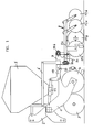
- FIG. 1 shows a side view of a combination in a schematically simplified form Soil cultivation device and seeder for attachment to a tractor or the like.
- the combination consists of a frame 1 with mounting mechanism 2 and Clearing discs 3 and a roller 4 composed of discs, further from one seed hopper 5 mounted on the frame, one on the frame via an articulated frame 6 attached sowing rails 7, and a number of distributed over the working width, each coulter units 8 articulated to the sowing rail 7.
- Each coulter unit 8 consists of a support tube 9a or 9b, which with its front End is articulated on a transverse axis 10a or 10b of the sowing rail 7, further from a Disc coulters designed coulters 11a and 11b, and one of the coulters downstream Pressure roller 12a or 12b.
- the coulters are in two with longitudinal spacing (based on the length of the Seed drill) arranged rows, namely a front row with the coulters 11 a and a rear row with the coulters 11b.
- the towards the working width Successive coulters are alternately as front coulters 11a and rear coulters 11b arranged so that a staggered arrangement of the coulters over the working width is generated to blockages from earth, straw remains and the like to prevent that would occur if all coulters were placed side by side would be and would have correspondingly small distances from each other.
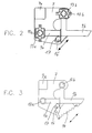
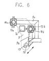
- the two transverse axes 10a and 10b of the sowing rail 7 are, like FIGS. 1 to 3 and 5 and 6 show arranged at a longitudinal distance (in the direction of the drill length) from one another.
- these transverse axes 10a and 10b also vertically offset from one another in such a way that the rear transverse axis 10b is arranged higher than the front transverse axis 10a.
- the rectilinear support tubes 9a of the front coulters 11a articulated while on the rear higher transverse axis 10b, the angular support tubes 9b rear coulters 11b are articulated.
- coulters are all biased downwards. This is done according to the figures 2, 5 and 6 through the rubber bearings 13a and 13b on the transverse axes 10a and 10b; According to Figure 3, this is done by tension springs 14, which are between the sowing rail and the respective support tube 9a and 9b are arranged. This means that each coulter unit with a coulter 11a or 11b and the associated pressure roller 12a or 12b biased against the floor, the support on the floor is carried out by the pressure roller 12a or 12b.
- FIGS. 2 and 3 and 5 and 6 also show a depth limit stop 16 on the sowing rail 7, which runs in the transverse direction over the entire sowing rail and all Support tubes 9a and 9b is assigned together.
- This stop 16 serves as a Depth limitation, so that the coulters in question are also in soft ground the pressure roller cannot lower any further than the support tube touches the stop, and on the other hand when lifting the sowing rail with the coulter units from Bottom support tubes so that they do not due to the bias acting on them Swing down indefinitely. It is important that the support tubes 9a and 9b for the front and rear coulters 11a and 11b until the Can only swing down the stop by the same amount.
- the straight support tubes 9a of the front coulters 11a with their underside directly on the top of the stop 16 hang up.
- the angular support tubes 9b of the rear coulters 11b is the vertical leg of the angled support tubes slightly extended downwards, so that he can in turn cooperate with the stop 16, although in terms of Interaction of the support tube 9a with the stop in a 90 ° offset Direction.
- the distance between the support tubes 9a and 9b is in the working position, this means with share units sitting on the ground at the same depth from the stop 16 an equally large small distance.
- a guide slot 17 in the sowing rail can also be seen from FIGS. 2, 3, 5 and 6, in which the stop 16 can be adjusted in an oblique direction, so that be Distance from the support tubes 9a and the support tubes 9b always changed in the same way, these distances are always the same value regardless of the absolute size to have.
- Both a displacement mechanism and, for example, can be used for adjustment an eccentric mechanism apply, which is not explained here needs.
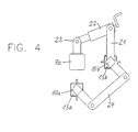
- FIG 4 shows schematically an arrangement for the simultaneous generation of the required Preload on all rubber bearings on both transverse axles.
- This biasing mechanism is not shown in Figures 2, 5 and 6 for clarity of illustration.
- the two transverse axes are again labeled 10a and 10b, the rubber bearings and Rubber joints for articulating the support tubes 9a and 9b are again with 13a and 13b designated.
- a lever 21 is arranged, the free end of which a length-adjustable cylinder or spindle unit 22 with a on the frame tube 7a Seed rail 7 arranged fixed abutment 23 is connected.
- the springs 14 can on an adjustable common Abutment can be hooked in to a central setting of the prestressing of the carrier tubes 9a, 9b.
- tension springs compression springs are also possible.
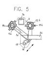
- FIGS. 5 and 6 show two more Embodiments of the invention with a modified arrangement of the transverse axes 10a and 10b such that they are arranged at approximately the same height.
- the coulter tubes 9a and 9b each angled. They each work with the same thing Stop 16 together for depth limitation.
- the two transverse axes 10a and 10b are approximately the same Height position arranged.
- the two transverse axes 10a and 10b are somewhat offset in height, the front transverse axis 10a being arranged somewhat higher than the rear transverse axis 10b is.
- the setting of the working depth of the coulter units takes place, as can be seen from the figure 1 results, by means of a joint frame 6 on which the sowing rail 7 is arranged, acting mechanism.
- This mechanism has an angle lever 18, which means of a screw spindle gear 19 by lengthening or shortening the spindle length is pivotable and with its leg 20 acting on the sowing rail 7, a height adjustment the sowing rail and thus a change in the working depth.
- the articulated frame 6 causes a parallel guide, so that the orientation of the sowing rail 7 with the coulter units 8 remains the same.
- the coulter units are lifted by lifting the entire combination with the frame and the roller mill by the tractor hydraulics.
- support tubes 9b and possibly not connected to a third transverse axis support tubes necessarily have to run at an angle, as shown in FIGS. 1 to 3, but can also run in a straight line and separate stop arms for interaction can have with the stop.
- the common stop 16 is a continuous one Crossbar has been described, which can be moved for the purpose of adjusting the depth limit is that with respect to the stop arms of all coulter beams approximately one even displacement distance results.
- the common stop 16 also be formed by a camshaft or a similar construction, in which the adjustment in order to change the depth limit either by turning or can be done by moving.
Landscapes
- Life Sciences & Earth Sciences (AREA)
- Soil Sciences (AREA)
- Environmental Sciences (AREA)
- Engineering & Computer Science (AREA)
- Mechanical Engineering (AREA)
- Zoology (AREA)
- Sowing (AREA)
- Combined Means For Separation Of Solids (AREA)
- Pretreatment Of Seeds And Plants (AREA)
- Soil Working Implements (AREA)
Abstract
Description
- Fig. 1
- in schematischer Seitenansicht eine Kombination aus Bodenbearbeitungsgerät und Sämaschine mit Rahmen, Walzenwerk, Saatgutbehälter, Säschiene und Schareinheiten,
- Fig. 2
- eine vergrößerte Darstellung der Säschiene in Seitenansicht wie in Figur 1 mit Gummilagervorspannung der Schareinheiten,
- Fig. 3
- eine Darstellung ähnlich Fig. 2 mit Federvorspannung der Schareinheiten, und
- Fig. 4
- schematisch eine Anordnung zur Vorspannung der Gummilager bei der Anordnung nach Fig. 2.
- Fig. 5
- eine Darstellung ähnlich Figur 2 eines abgewandelten Ausführungsbeispiels nach der Erfindung, und
- Fig. 6
- ein noch weiteres Ausführungsbeispiel der Erfindung.
Claims (7)
- Säschiene mit mehreren Säscharen mit jeweils nachgeordneter Druckrolle, mit folgenden Merkmalen:es sind mindestens zwei in Arbeitsrichtung hintereinander angeordnete Reihen von Säscharen (11a, 11b) in gestaffelter Anordnung mit jeweils nachgeordneter Druckrolle (12a, 12b) vorgesehen,die Säschiene (7) weist mindestens zwei jeweils einer der Reihen von Säscharen zugeordnete Querachsen (10a, 10b) auf, an denen jede Säschar (9a bzw. 9b) der betreffenden Säscharreihe über einen länglichen Träger (9a, 9b) angelenkt ist, wobei eine die jeweilige aus Träger, Säschar und Druckrolle gebildete Einheit (8) nach unten drückende Vorspannung erzeugt wird,die mindestens zwei Querachsen haben in Arbeitsrichtung einen Abstand voneinander, der etwa dem Abstand der beiden Säscharreihen entspricht, wobei die beiden Querachsen sich in der gleichen Höhenposition befinden oder relativ zueinander höhenversetzt positioniert sein können,die mit den beiden Querachsen (10a, 10b) verbundenen Säscharträger (9a, 9b) wirken alle mit einem gemeinsamen Anschlag (16) zur Tiefenbegrenzung zusammen,die mit den beiden Querachsen (10a, 10b) verbundenen Säscharträger (9a, 9b) wirken jeweils mit unter verschiedenen Winkeln verlaufenden Anschlagarmen mit dem gemeinsamen Anschlag (16) zusammen, wobei die Anordnung so getroffen ist, daß die Längendistanz jedes Anschlagarms von der betreffenenden Querachse (10a bzw. 10b) zur Anschlagstelle etwa gleich ist.
- Säschiene nach Anspruch 1, wobei der gemeinsame Anschlag (16) zwecks Verstellung der Tiefenbegrenzung längs einer Bahn verschiebbar ist, die eine gleichmäßige Verschiebedistanz mit Bezug auf die Anschlagarme aller Säscharträger ergibt.
- Säschiene nach Anspruch 1, wobei der gemeinsame Anschlag (16) durch eine Nockenwelle oder dergleichen gebildet ist, die durch Drehen oder Verschieben zwecks Veränderung der Tiefenbegrenzung so verstellbar ist, daß sich eine etwa gleiche Verstelldistanz mit Bezug auf die Anschlagarme sämtlicher Säscharträger ergibt.
- Säschiene nach einem der Ansprüche 1 bis 3, wobei jeder Scharträger (9a, 9b) über ein mit Torsionsvorspannung ausgestattetes Gummigelenk (13a, 13b) mit der betreffenden Querachse verbunden ist.
- Säschiene nach Anspruch 4, wobei die beiden Querachsen (10a, 10b) zwecks gemeinsamer Vorspannung der Gummigelenke (13a, 13b) über einen Parallelkurbelmechanismus (24) oder einen gleichwirkenden Mechanismus miteinander gekuppelt sind und eine (10b) der Querachsen mit einem Mechanismus (21, 22) zur Erzeugung einer Winkeldrehbewegung verbunden ist.
- Säschiene nach einem der Ansprüche 1 bis 3, wobei jeder Scharträger (9a, 9b) über eine Zug- oder Druckfeder nach unten vorgespannt ist und zwecks gemeinsamer Vorspanneinstellung das allen Federn gemeinsame Federwiderlager verstellbar ist.
- Säschiene nach einem der Ansprüche 1 bis 6, wobei die Höhe der Säschiene (7) über einen parallel führenden Gelenkrahmen (6) verstellbar ist.
Applications Claiming Priority (2)
| Application Number | Priority Date | Filing Date | Title |
|---|---|---|---|
| DE10238685 | 2002-08-19 | ||
| DE10238685A DE10238685A1 (de) | 2002-08-19 | 2002-08-19 | Säschiene mit mehreren gestaffelt angeordneten Säscharen mit nachgeordneten Druckrollen |
Publications (2)
| Publication Number | Publication Date |
|---|---|
| EP1391147A1 true EP1391147A1 (de) | 2004-02-25 |
| EP1391147B1 EP1391147B1 (de) | 2005-11-30 |
Family
ID=30775530
Family Applications (1)
| Application Number | Title | Priority Date | Filing Date |
|---|---|---|---|
| EP03012526A Expired - Lifetime EP1391147B1 (de) | 2002-08-19 | 2003-06-02 | Säschiene mit mehreren gestaffelt angeordneten Säscharen mit nachgeordneten Druckrollen |
Country Status (3)
| Country | Link |
|---|---|
| EP (1) | EP1391147B1 (de) |
| AT (1) | ATE311095T1 (de) |
| DE (2) | DE10238685A1 (de) |
Cited By (12)
| Publication number | Priority date | Publication date | Assignee | Title |
|---|---|---|---|---|
| FR2896659A1 (fr) * | 2006-01-27 | 2007-08-03 | Sulky Burel Soc Par Actions Si | Semoir comportant une serie de bras, porteurs de disques semeurs et de rouleaux suiveurs, supportes sous le chassis par l'intermediaire d'articulations elastiques |
| EP1964459A1 (de) * | 2007-03-02 | 2008-09-03 | Rauch Landmaschinenfabrik Gmbh | Sämaschine |
| ITPD20110048A1 (it) * | 2011-02-18 | 2012-08-19 | Maschio Gaspardo Spa | Seminatrice con elementi di semina a ranghi multipli |
| EP2982231A1 (de) * | 2014-08-05 | 2016-02-10 | Amazonen-Werke H. Dreyer GmbH & Co. KG | Sämaschine mit mehreren säscharreihen |
| US9668401B2 (en) | 2015-06-30 | 2017-06-06 | Cnh Industrial America Llc | Down stop for agricultural closing discs |
| US9699954B2 (en) | 2015-06-30 | 2017-07-11 | Cnh Industrial America Llc | Adjustable down stop for agricultural closing discs |
| CN111066429A (zh) * | 2020-01-15 | 2020-04-28 | 河南科技学院 | 一种高密度棉花播种机 |
| DE202019100926U1 (de) | 2019-02-19 | 2020-05-20 | Pöttinger Landtechnik Gmbh | Vorrichtung für eine landwirtschaftliche Maschine |
| EP3698617A2 (de) | 2019-02-19 | 2020-08-26 | PÖTTINGER Landtechnik GmbH | Scharsystem für eine landwirtschaftliche maschine |
| CN114287210A (zh) * | 2022-01-05 | 2022-04-08 | 刘爱玲 | 一种玉米精量播种机 |
| CN115399096A (zh) * | 2022-08-31 | 2022-11-29 | 山东鲁研农业良种有限公司 | 一种具有播种深度调节功能的小麦播种装置 |
| EP4311413A1 (de) * | 2022-07-26 | 2024-01-31 | Amazonen-Werke H. Dreyer SE & Co. KG | Landwirtschaftliche maschine |
Families Citing this family (3)
| Publication number | Priority date | Publication date | Assignee | Title |
|---|---|---|---|---|
| US10111376B2 (en) * | 2016-03-30 | 2018-10-30 | Steering Solutions Ip Holding Corporation | Seed depth auto-learn system associated with a seed depth device for an agricultural planter |
| CN111201859A (zh) * | 2020-01-09 | 2020-05-29 | 黑龙江省农业科学院畜牧兽医分院 | 一种农业机械用玉米播种装置 |
| US20230148469A1 (en) * | 2021-11-15 | 2023-05-18 | Deere & Company | Seeding row unit having a primary actuator to adjust depth and to raise and lower the seeding row unit |
Citations (7)
| Publication number | Priority date | Publication date | Assignee | Title |
|---|---|---|---|---|
| DE188347C (de) * | ||||
| WO1985005246A1 (en) * | 1984-05-21 | 1985-12-05 | Väderstadverken Ab | Apparatus in dispensing machines for agriculture |
| DE19644751A1 (de) | 1995-10-31 | 1997-05-07 | Lemken Gmbh & Co Kg | Drillmaschine mit Stellvorrichtung für Säschar und Druckrolle |
| DE19731862A1 (de) * | 1997-07-24 | 1999-01-28 | Amazonen Werke Dreyer H | Scheibensäscharanordnung |
| DE29910414U1 (de) | 1999-06-15 | 1999-08-26 | Horsch Maschinen GmbH, 92421 Schwandorf | Säscharanordnung |
| EP0974252A1 (de) * | 1998-07-20 | 2000-01-26 | Kuhn-Nodet S.A. | Sämaschine |
| EP1060649A2 (de) * | 1999-06-15 | 2000-12-20 | Horsch Maschinen GmbH | Schlepperbetriebene Sämaschine mit Säscharanordnung und Dreipunkt-Anhängung |
Family Cites Families (3)
| Publication number | Priority date | Publication date | Assignee | Title |
|---|---|---|---|---|
| SE410546B (sv) * | 1977-04-14 | 1979-10-22 | Stark Crister | Anordning vid ringvelt |
| DE3527760A1 (de) * | 1985-08-02 | 1987-02-12 | Amazonen Werke Dreyer H | Saemaschine |
| DE4323154C2 (de) * | 1993-06-29 | 1995-07-06 | Kleine Franz Maschf | Bodenbearbeitungsmaschine |
-
2002
- 2002-08-19 DE DE10238685A patent/DE10238685A1/de not_active Withdrawn
-
2003
- 2003-06-02 AT AT03012526T patent/ATE311095T1/de active
- 2003-06-02 EP EP03012526A patent/EP1391147B1/de not_active Expired - Lifetime
- 2003-06-02 DE DE50301789T patent/DE50301789D1/de not_active Expired - Lifetime
Patent Citations (7)
| Publication number | Priority date | Publication date | Assignee | Title |
|---|---|---|---|---|
| DE188347C (de) * | ||||
| WO1985005246A1 (en) * | 1984-05-21 | 1985-12-05 | Väderstadverken Ab | Apparatus in dispensing machines for agriculture |
| DE19644751A1 (de) | 1995-10-31 | 1997-05-07 | Lemken Gmbh & Co Kg | Drillmaschine mit Stellvorrichtung für Säschar und Druckrolle |
| DE19731862A1 (de) * | 1997-07-24 | 1999-01-28 | Amazonen Werke Dreyer H | Scheibensäscharanordnung |
| EP0974252A1 (de) * | 1998-07-20 | 2000-01-26 | Kuhn-Nodet S.A. | Sämaschine |
| DE29910414U1 (de) | 1999-06-15 | 1999-08-26 | Horsch Maschinen GmbH, 92421 Schwandorf | Säscharanordnung |
| EP1060649A2 (de) * | 1999-06-15 | 2000-12-20 | Horsch Maschinen GmbH | Schlepperbetriebene Sämaschine mit Säscharanordnung und Dreipunkt-Anhängung |
Cited By (17)
| Publication number | Priority date | Publication date | Assignee | Title |
|---|---|---|---|---|
| FR2896659A1 (fr) * | 2006-01-27 | 2007-08-03 | Sulky Burel Soc Par Actions Si | Semoir comportant une serie de bras, porteurs de disques semeurs et de rouleaux suiveurs, supportes sous le chassis par l'intermediaire d'articulations elastiques |
| EP1815730A1 (de) * | 2006-01-27 | 2007-08-08 | Sulky Burel | Sämaschine, die eine Reihe von Armen, Halterungen für Säscheiben und Nachläufer umfasst, die auf dem Rahmen mit Hilfe von elastischen Gelenken befestigt sind |
| EP1964459A1 (de) * | 2007-03-02 | 2008-09-03 | Rauch Landmaschinenfabrik Gmbh | Sämaschine |
| ITPD20110048A1 (it) * | 2011-02-18 | 2012-08-19 | Maschio Gaspardo Spa | Seminatrice con elementi di semina a ranghi multipli |
| WO2012110992A1 (en) | 2011-02-18 | 2012-08-23 | Maschio Gaspardo S.P.A. | Seed drill with multi-row sowing elements |
| CN103476240A (zh) * | 2011-02-18 | 2013-12-25 | 马斯奇奥盖斯帕多股份有限公司 | 具有多行播种元件的条播机 |
| EP2982231A1 (de) * | 2014-08-05 | 2016-02-10 | Amazonen-Werke H. Dreyer GmbH & Co. KG | Sämaschine mit mehreren säscharreihen |
| US9699954B2 (en) | 2015-06-30 | 2017-07-11 | Cnh Industrial America Llc | Adjustable down stop for agricultural closing discs |
| US9668401B2 (en) | 2015-06-30 | 2017-06-06 | Cnh Industrial America Llc | Down stop for agricultural closing discs |
| US9992926B2 (en) | 2015-06-30 | 2018-06-12 | Cnh Industrial America Llc | Down stop for agricultural closing discs |
| DE202019100926U1 (de) | 2019-02-19 | 2020-05-20 | Pöttinger Landtechnik Gmbh | Vorrichtung für eine landwirtschaftliche Maschine |
| EP3698617A2 (de) | 2019-02-19 | 2020-08-26 | PÖTTINGER Landtechnik GmbH | Scharsystem für eine landwirtschaftliche maschine |
| EP3698617A3 (de) * | 2019-02-19 | 2020-10-21 | PÖTTINGER Landtechnik GmbH | Scharsystem für eine landwirtschaftliche maschine |
| CN111066429A (zh) * | 2020-01-15 | 2020-04-28 | 河南科技学院 | 一种高密度棉花播种机 |
| CN114287210A (zh) * | 2022-01-05 | 2022-04-08 | 刘爱玲 | 一种玉米精量播种机 |
| EP4311413A1 (de) * | 2022-07-26 | 2024-01-31 | Amazonen-Werke H. Dreyer SE & Co. KG | Landwirtschaftliche maschine |
| CN115399096A (zh) * | 2022-08-31 | 2022-11-29 | 山东鲁研农业良种有限公司 | 一种具有播种深度调节功能的小麦播种装置 |
Also Published As
| Publication number | Publication date |
|---|---|
| EP1391147B1 (de) | 2005-11-30 |
| ATE311095T1 (de) | 2005-12-15 |
| DE10238685A1 (de) | 2004-03-11 |
| DE50301789D1 (de) | 2006-01-05 |
Similar Documents
| Publication | Publication Date | Title |
|---|---|---|
| DE2830195C2 (de) | Drillmaschine | |
| DE10066238B4 (de) | Landwirtschaftsmaschine in Form einer Scheibenegge | |
| EP2949192B1 (de) | Pflug mit mehreren an einem pflugbalken angebrachten pflugkörpern | |
| EP1391147B1 (de) | Säschiene mit mehreren gestaffelt angeordneten Säscharen mit nachgeordneten Druckrollen | |
| DE3407501C2 (de) | Bestellgerät für die Landwirtschaft | |
| DE102017120948B4 (de) | Gezogenes landwirtschaftliches Arbeitsgerät | |
| EP0426960B1 (de) | Hackvorrichtung für ein Bodenbearbeitungsgerät | |
| EP1964459B1 (de) | Sämaschine | |
| DE2829705A1 (de) | Vorrichtung fuer die bodenbearbeitung | |
| DE29605356U1 (de) | Sägerät, insbesondere für Mulchsaat | |
| DE19630079A1 (de) | Bodenbearbeitungsgerät mit Hohlscheiben | |
| DE10137624A1 (de) | Scheibenschar | |
| EP3381253A1 (de) | Landwirtschaftliche maschine mit tiefenführungselementen | |
| EP0445582B1 (de) | Bodenbearbeitungsgerät | |
| EP3127412A1 (de) | Landwirtschaftliche maschine zum bearbeiten eines bodens und zum ausbringen von saatgut | |
| EP0445583B1 (de) | Bodenbearbeitungsgerät | |
| EP0858258B1 (de) | Drillmaschine mit stellvorrichtung für säschar und druckrolle | |
| DE3033144C2 (de) | Schleppergezogene Bodenbearbeitungs- und Sämaschine | |
| EP3698617B1 (de) | Scharsystem für eine landwirtschaftliche maschine | |
| DE69826145T2 (de) | Landwirtschaftliche maschine | |
| EP2628372A1 (de) | Einrichtung zur streifenweisen landwirtschaftlichen Bearbeitung von Böden | |
| DE102022104506A1 (de) | Bodenbearbeitungsmaschine | |
| EP4216701A1 (de) | Scheiben-wendepflug mit auswechselbar ausgebildeten pflugmodulen | |
| DE3707758A1 (de) | Saatbettkombination | |
| DE1959021C3 (de) | Egge, insbesondere zum Anbau an die Dreipunkt-Anhängevorrichtung eines Ackerschleppers |
Legal Events
| Date | Code | Title | Description |
|---|---|---|---|
| PUAI | Public reference made under article 153(3) epc to a published international application that has entered the european phase |
Free format text: ORIGINAL CODE: 0009012 |
|
| AK | Designated contracting states |
Kind code of ref document: A1 Designated state(s): AT BE BG CH CY CZ DE DK EE ES FI FR GB GR HU IE IT LI LU MC NL PT RO SE SI SK TR |
|
| AX | Request for extension of the european patent |
Extension state: AL LT LV MK |
|
| 17P | Request for examination filed |
Effective date: 20040807 |
|
| AKX | Designation fees paid |
Designated state(s): AT BE BG CH CY CZ DE DK EE ES FI FR GB GR HU IE IT LI LU MC NL PT RO SE SI SK TR |
|
| 17Q | First examination report despatched |
Effective date: 20041129 |
|
| GRAP | Despatch of communication of intention to grant a patent |
Free format text: ORIGINAL CODE: EPIDOSNIGR1 |
|
| GRAS | Grant fee paid |
Free format text: ORIGINAL CODE: EPIDOSNIGR3 |
|
| GRAA | (expected) grant |
Free format text: ORIGINAL CODE: 0009210 |
|
| AK | Designated contracting states |
Kind code of ref document: B1 Designated state(s): AT BE BG CH CY CZ DE DK EE ES FI FR GB GR HU IE IT LI LU MC NL PT RO SE SI SK TR |
|
| PG25 | Lapsed in a contracting state [announced via postgrant information from national office to epo] |
Ref country code: SK Free format text: LAPSE BECAUSE OF FAILURE TO SUBMIT A TRANSLATION OF THE DESCRIPTION OR TO PAY THE FEE WITHIN THE PRESCRIBED TIME-LIMIT Effective date: 20051130 Ref country code: SI Free format text: LAPSE BECAUSE OF FAILURE TO SUBMIT A TRANSLATION OF THE DESCRIPTION OR TO PAY THE FEE WITHIN THE PRESCRIBED TIME-LIMIT Effective date: 20051130 Ref country code: IE Free format text: LAPSE BECAUSE OF FAILURE TO SUBMIT A TRANSLATION OF THE DESCRIPTION OR TO PAY THE FEE WITHIN THE PRESCRIBED TIME-LIMIT Effective date: 20051130 Ref country code: FI Free format text: LAPSE BECAUSE OF FAILURE TO SUBMIT A TRANSLATION OF THE DESCRIPTION OR TO PAY THE FEE WITHIN THE PRESCRIBED TIME-LIMIT Effective date: 20051130 Ref country code: RO Free format text: LAPSE BECAUSE OF FAILURE TO SUBMIT A TRANSLATION OF THE DESCRIPTION OR TO PAY THE FEE WITHIN THE PRESCRIBED TIME-LIMIT Effective date: 20051130 Ref country code: CZ Free format text: LAPSE BECAUSE OF FAILURE TO SUBMIT A TRANSLATION OF THE DESCRIPTION OR TO PAY THE FEE WITHIN THE PRESCRIBED TIME-LIMIT Effective date: 20051130 Ref country code: NL Free format text: LAPSE BECAUSE OF FAILURE TO SUBMIT A TRANSLATION OF THE DESCRIPTION OR TO PAY THE FEE WITHIN THE PRESCRIBED TIME-LIMIT Effective date: 20051130 Ref country code: IT Free format text: LAPSE BECAUSE OF FAILURE TO SUBMIT A TRANSLATION OF THE DESCRIPTION OR TO PAY THE FEE WITHIN THE PRESCRIBED TIME-LIMIT;WARNING: LAPSES OF ITALIAN PATENTS WITH EFFECTIVE DATE BEFORE 2007 MAY HAVE OCCURRED AT ANY TIME BEFORE 2007. THE CORRECT EFFECTIVE DATE MAY BE DIFFERENT FROM THE ONE RECORDED. Effective date: 20051130 |
|
| REG | Reference to a national code |
Ref country code: CH Ref legal event code: EP Ref country code: GB Ref legal event code: FG4D Free format text: NOT ENGLISH |
|
| GBT | Gb: translation of ep patent filed (gb section 77(6)(a)/1977) |
Effective date: 20051201 |
|
| REG | Reference to a national code |
Ref country code: IE Ref legal event code: FG4D Free format text: LANGUAGE OF EP DOCUMENT: GERMAN |
|
| REF | Corresponds to: |
Ref document number: 50301789 Country of ref document: DE Date of ref document: 20060105 Kind code of ref document: P |
|
| PG25 | Lapsed in a contracting state [announced via postgrant information from national office to epo] |
Ref country code: GR Free format text: LAPSE BECAUSE OF FAILURE TO SUBMIT A TRANSLATION OF THE DESCRIPTION OR TO PAY THE FEE WITHIN THE PRESCRIBED TIME-LIMIT Effective date: 20060228 Ref country code: DK Free format text: LAPSE BECAUSE OF FAILURE TO SUBMIT A TRANSLATION OF THE DESCRIPTION OR TO PAY THE FEE WITHIN THE PRESCRIBED TIME-LIMIT Effective date: 20060228 Ref country code: BG Free format text: LAPSE BECAUSE OF FAILURE TO SUBMIT A TRANSLATION OF THE DESCRIPTION OR TO PAY THE FEE WITHIN THE PRESCRIBED TIME-LIMIT Effective date: 20060228 |
|
| PG25 | Lapsed in a contracting state [announced via postgrant information from national office to epo] |
Ref country code: ES Free format text: LAPSE BECAUSE OF FAILURE TO SUBMIT A TRANSLATION OF THE DESCRIPTION OR TO PAY THE FEE WITHIN THE PRESCRIBED TIME-LIMIT Effective date: 20060313 |
|
| REG | Reference to a national code |
Ref country code: SE Ref legal event code: TRGR |
|
| PG25 | Lapsed in a contracting state [announced via postgrant information from national office to epo] |
Ref country code: PT Free format text: LAPSE BECAUSE OF FAILURE TO SUBMIT A TRANSLATION OF THE DESCRIPTION OR TO PAY THE FEE WITHIN THE PRESCRIBED TIME-LIMIT Effective date: 20060502 |
|
| NLV1 | Nl: lapsed or annulled due to failure to fulfill the requirements of art. 29p and 29m of the patents act | ||
| PG25 | Lapsed in a contracting state [announced via postgrant information from national office to epo] |
Ref country code: HU Free format text: LAPSE BECAUSE OF FAILURE TO SUBMIT A TRANSLATION OF THE DESCRIPTION OR TO PAY THE FEE WITHIN THE PRESCRIBED TIME-LIMIT Effective date: 20060601 |
|
| PG25 | Lapsed in a contracting state [announced via postgrant information from national office to epo] |
Ref country code: MC Free format text: LAPSE BECAUSE OF NON-PAYMENT OF DUE FEES Effective date: 20060630 Ref country code: BE Free format text: LAPSE BECAUSE OF NON-PAYMENT OF DUE FEES Effective date: 20060630 |
|
| REG | Reference to a national code |
Ref country code: IE Ref legal event code: FD4D |
|
| ET | Fr: translation filed | ||
| PLBE | No opposition filed within time limit |
Free format text: ORIGINAL CODE: 0009261 |
|
| STAA | Information on the status of an ep patent application or granted ep patent |
Free format text: STATUS: NO OPPOSITION FILED WITHIN TIME LIMIT |
|
| 26N | No opposition filed |
Effective date: 20060831 |
|
| BERE | Be: lapsed |
Owner name: KERNER, JOSEF Effective date: 20060630 |
|
| REG | Reference to a national code |
Ref country code: CH Ref legal event code: PL |
|
| PG25 | Lapsed in a contracting state [announced via postgrant information from national office to epo] |
Ref country code: CH Free format text: LAPSE BECAUSE OF NON-PAYMENT OF DUE FEES Effective date: 20070630 Ref country code: LI Free format text: LAPSE BECAUSE OF NON-PAYMENT OF DUE FEES Effective date: 20070630 |
|
| PG25 | Lapsed in a contracting state [announced via postgrant information from national office to epo] |
Ref country code: EE Free format text: LAPSE BECAUSE OF FAILURE TO SUBMIT A TRANSLATION OF THE DESCRIPTION OR TO PAY THE FEE WITHIN THE PRESCRIBED TIME-LIMIT Effective date: 20051130 |
|
| PG25 | Lapsed in a contracting state [announced via postgrant information from national office to epo] |
Ref country code: LU Free format text: LAPSE BECAUSE OF NON-PAYMENT OF DUE FEES Effective date: 20060602 Ref country code: TR Free format text: LAPSE BECAUSE OF FAILURE TO SUBMIT A TRANSLATION OF THE DESCRIPTION OR TO PAY THE FEE WITHIN THE PRESCRIBED TIME-LIMIT Effective date: 20051130 |
|
| PG25 | Lapsed in a contracting state [announced via postgrant information from national office to epo] |
Ref country code: CY Free format text: LAPSE BECAUSE OF FAILURE TO SUBMIT A TRANSLATION OF THE DESCRIPTION OR TO PAY THE FEE WITHIN THE PRESCRIBED TIME-LIMIT Effective date: 20051130 |
|
| PGFP | Annual fee paid to national office [announced via postgrant information from national office to epo] |
Ref country code: GB Payment date: 20090623 Year of fee payment: 7 |
|
| PGFP | Annual fee paid to national office [announced via postgrant information from national office to epo] |
Ref country code: SE Payment date: 20100622 Year of fee payment: 8 |
|
| GBPC | Gb: european patent ceased through non-payment of renewal fee |
Effective date: 20100602 |
|
| PG25 | Lapsed in a contracting state [announced via postgrant information from national office to epo] |
Ref country code: GB Free format text: LAPSE BECAUSE OF NON-PAYMENT OF DUE FEES Effective date: 20100602 |
|
| REG | Reference to a national code |
Ref country code: SE Ref legal event code: EUG |
|
| PG25 | Lapsed in a contracting state [announced via postgrant information from national office to epo] |
Ref country code: SE Free format text: LAPSE BECAUSE OF NON-PAYMENT OF DUE FEES Effective date: 20110603 |
|
| PGFP | Annual fee paid to national office [announced via postgrant information from national office to epo] |
Ref country code: AT Payment date: 20140618 Year of fee payment: 12 |
|
| PGFP | Annual fee paid to national office [announced via postgrant information from national office to epo] |
Ref country code: FR Payment date: 20140617 Year of fee payment: 12 |
|
| REG | Reference to a national code |
Ref country code: AT Ref legal event code: MM01 Ref document number: 311095 Country of ref document: AT Kind code of ref document: T Effective date: 20150602 |
|
| REG | Reference to a national code |
Ref country code: FR Ref legal event code: ST Effective date: 20160229 |
|
| PG25 | Lapsed in a contracting state [announced via postgrant information from national office to epo] |
Ref country code: FR Free format text: LAPSE BECAUSE OF NON-PAYMENT OF DUE FEES Effective date: 20150630 Ref country code: AT Free format text: LAPSE BECAUSE OF NON-PAYMENT OF DUE FEES Effective date: 20150602 |
|
| PGFP | Annual fee paid to national office [announced via postgrant information from national office to epo] |
Ref country code: DE Payment date: 20160816 Year of fee payment: 14 |
|
| REG | Reference to a national code |
Ref country code: DE Ref legal event code: R119 Ref document number: 50301789 Country of ref document: DE |
|
| PG25 | Lapsed in a contracting state [announced via postgrant information from national office to epo] |
Ref country code: DE Free format text: LAPSE BECAUSE OF NON-PAYMENT OF DUE FEES Effective date: 20180103 |