EP1391432A1 - Apparatus for bending and annealing glass panels - Google Patents
Apparatus for bending and annealing glass panels Download PDFInfo
- Publication number
- EP1391432A1 EP1391432A1 EP03101621A EP03101621A EP1391432A1 EP 1391432 A1 EP1391432 A1 EP 1391432A1 EP 03101621 A EP03101621 A EP 03101621A EP 03101621 A EP03101621 A EP 03101621A EP 1391432 A1 EP1391432 A1 EP 1391432A1
- Authority
- EP
- European Patent Office
- Prior art keywords
- sections
- cooling
- mould
- bending
- glass panels
- Prior art date
- Legal status (The legal status is an assumption and is not a legal conclusion. Google has not performed a legal analysis and makes no representation as to the accuracy of the status listed.)
- Granted
Links
- 238000005452 bending Methods 0.000 title claims abstract description 47
- 239000011521 glass Substances 0.000 title claims abstract description 42
- 238000000137 annealing Methods 0.000 title claims abstract description 7
- 238000001816 cooling Methods 0.000 claims abstract description 59
- 239000000969 carrier Substances 0.000 claims abstract description 32
- 238000010438 heat treatment Methods 0.000 claims abstract description 29
- 230000005855 radiation Effects 0.000 claims description 14
- 239000002826 coolant Substances 0.000 claims description 11
- 238000011144 upstream manufacturing Methods 0.000 claims description 5
- 238000007665 sagging Methods 0.000 claims description 3
- 238000007507 annealing of glass Methods 0.000 claims description 2
- 230000001105 regulatory effect Effects 0.000 claims description 2
- 238000007664 blowing Methods 0.000 description 2
- 230000000694 effects Effects 0.000 description 2
- 230000000712 assembly Effects 0.000 description 1
- 238000000429 assembly Methods 0.000 description 1
- 230000003247 decreasing effect Effects 0.000 description 1
- 230000001419 dependent effect Effects 0.000 description 1
- 238000005538 encapsulation Methods 0.000 description 1
- 238000000034 method Methods 0.000 description 1
- 238000011084 recovery Methods 0.000 description 1
- XLYOFNOQVPJJNP-UHFFFAOYSA-N water Substances O XLYOFNOQVPJJNP-UHFFFAOYSA-N 0.000 description 1
Images




Classifications
-
- C—CHEMISTRY; METALLURGY
- C03—GLASS; MINERAL OR SLAG WOOL
- C03B—MANUFACTURE, SHAPING, OR SUPPLEMENTARY PROCESSES
- C03B23/00—Re-forming shaped glass
- C03B23/02—Re-forming glass sheets
- C03B23/023—Re-forming glass sheets by bending
- C03B23/025—Re-forming glass sheets by bending by gravity
- C03B23/0258—Gravity bending involving applying local or additional heating, cooling or insulating means
-
- C—CHEMISTRY; METALLURGY
- C03—GLASS; MINERAL OR SLAG WOOL
- C03B—MANUFACTURE, SHAPING, OR SUPPLEMENTARY PROCESSES
- C03B23/00—Re-forming shaped glass
- C03B23/02—Re-forming glass sheets
- C03B23/023—Re-forming glass sheets by bending
- C03B23/03—Re-forming glass sheets by bending by press-bending between shaping moulds
- C03B23/0307—Press-bending involving applying local or additional heating, cooling or insulating means
-
- C—CHEMISTRY; METALLURGY
- C03—GLASS; MINERAL OR SLAG WOOL
- C03B—MANUFACTURE, SHAPING, OR SUPPLEMENTARY PROCESSES
- C03B25/00—Annealing glass products
- C03B25/04—Annealing glass products in a continuous way
- C03B25/06—Annealing glass products in a continuous way with horizontal displacement of the glass products
- C03B25/08—Annealing glass products in a continuous way with horizontal displacement of the glass products of glass sheets
-
- C—CHEMISTRY; METALLURGY
- C03—GLASS; MINERAL OR SLAG WOOL
- C03B—MANUFACTURE, SHAPING, OR SUPPLEMENTARY PROCESSES
- C03B29/00—Reheating glass products for softening or fusing their surfaces; Fire-polishing; Fusing of margins
- C03B29/04—Reheating glass products for softening or fusing their surfaces; Fire-polishing; Fusing of margins in a continuous way
- C03B29/06—Reheating glass products for softening or fusing their surfaces; Fire-polishing; Fusing of margins in a continuous way with horizontal displacement of the products
- C03B29/08—Glass sheets
-
- C—CHEMISTRY; METALLURGY
- C03—GLASS; MINERAL OR SLAG WOOL
- C03B—MANUFACTURE, SHAPING, OR SUPPLEMENTARY PROCESSES
- C03B35/00—Transporting of glass products during their manufacture, e.g. hot glass lenses, prisms
- C03B35/14—Transporting hot glass sheets or ribbons, e.g. by heat-resistant conveyor belts or bands
- C03B35/20—Transporting hot glass sheets or ribbons, e.g. by heat-resistant conveyor belts or bands by gripping tongs or supporting frames
- C03B35/202—Transporting hot glass sheets or ribbons, e.g. by heat-resistant conveyor belts or bands by gripping tongs or supporting frames by supporting frames
Definitions
- the invention relates to an apparatus for bending glass panels, said apparatus comprising
- the apparatus of figs. 1-3 comprises an upper mould carrier track 1, including successive mould carriers 9 whose front or back wall 11 separates successive preheating sections 2, 3 and a plurality of successive bending sections 4a, 4b from each other.
- the mould carriers 9 are adapted to be intermittently conveyable towards a final bending section 4b, having its ceiling provided with a descendable and hoistable male mould 22.
- a lower mould carrier track 21 includes successive mould carriers 9 which lie underneath those of the upper track 1.
- the mould carriers 9 of the lower mould carrier track 21 have their back or front wall 11 separate successive cooling sections 5, 6, 7 from each other.
- the mould carriers 9 of the lower mould carrier track 21 are adapted to be intermittently conveyable in the direction opposite to the conveying direction of mould carriers present on the upper track.
- Each mould carrier 9 is provided with a bending mould 12 supported by the mould carrier 9.
- a pair of glass panels is set on the bending mould 12 while the mould carrier is positioned outside the furnace in a loading and unloading section 8.
- the carrier 9, the mould 12, and the pair of glass panels to be bent are hoisted by means of a lift present in a section 8a following the loading and unloading section 8 up onto the upper track 1, along which the mould carriers are conveyed intermittently through a distance substantially equal to the carrier length at a time towards the bending section 4b.
- First in this passage are preheating sections 2, in which the heating is based on forced convection, the thermal energy of which is recovered from glass panels presently annealing by forced convection in bottom cooling sections 7.
- the cooling sections 7 can be used for speeding up the annealing of glass panels to be cooled and the heating sections 2 can be used for speeding up the heating of glass panels to be heated while exploiting more effectively the thermal energy of glass panels to be cooled.
- the structural and functional aspects of the sections 2 and 7 are described in more detail in the Applicant's patent publication US-4,986,842.
- the difference in this case is that a first preheating section 2a is supplied with hot air by way of a duct 24 from upstream end cooling sections 5 of the lower track, each of which is individually provided with controlled cooling air circulation by means of exhaust fans 23.
- Providing the sections 5 with an individually regulable cooling air circulation enables cooling of a glass panel in a controlled fashion and establishing a sufficiently high edge tension.
- the upper level carriers 9 arrive in preheating sections 3, in which the principal heating of glass panels is effected by means of radiation heating.
- the sections 3 have their ceilings provided with electrically heated radiation heating resistances 13.
- the sections 3 have a thermally insulated floor 15a, which constitutes an intermediate floor between the upper track sections 3 and lower track sections 6.
- radiation heating elements 16 set below the level of the carriers' 9 bottom 10.
- the radiation heating elements 16 apply heat to the bottom panel in a pair of glass panels presently in the sections 3 through the open-structured bottom 10 of the carrier 9.
- the bottom 10 need not be a fully open structure, as it can be partially covered e.g. with a thin perforated sheet, a screen, or the like, which is transmissive both to convection air in the preceding sections 2 and to radiation heat from the heating elements 16.
- Fig. 6 illustrates rails 18 present at the ends of the carrier's 9 bottom frame 10, whereby the carriers 9 are propped on rollers 19, which are mounted with bearings on side walls 17 of the furnace (fig. 7) and thus constitute the upper track 1 and the lower track 21.
- Fig. 7 shows an example regarding the radiation heating elements 16 present on top of the intermediate floors 15, 15a.
- Those can be open resistances, which are divided for resistance rod elements 16a, 16b side by side in the lateral direction of the sections and which have individually regulable heating effects.
- the final preheating section 3a is followed by a number of prebending sections 4a, in which the temperate of a pair of glass panels rises to such a degree that the pair of glass panels begins to sag upon the ring 12 supporting the same.
- the number of prebending sections 4a is sufficient for the gravitational sagging to reach an ultimate bending form in the final prebending section 4a in the case of simple bending forms and almost an ultimate bending form in the case of complex bending forms.
- the bending is finished by using a hoistable and descendable male mould 22 present in the bending section 4b for pressing a finished form or shape.
- the mould 22 is maintained at a sufficiently high temperature by resistances 14b.
- the bending temperature of glass is in the range of 590°C - 635°C.
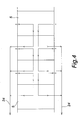
- FIG. 4 visualizes a flow pattern established by means of the intermediate floor structure of fig. 3. On top of four sections 5 are established three successive cooling zones, which have an individual exhaust fan 23. The blowing capacity of each fan 23 is regulable by means of an inverter. Fig.
- each section 5 has its individual exhaust fan 23, the blowing capacity of which is regulable by means of an inverter. Consequently, the successive cooling zones and/or sections 5 have cooling capacities individually adjustable.
- the cooling sections 5 can have their bottom below the glass panel provided with meandering cooling pipe systems, which are supplied with cooling air by fans from the opposite sides of the sections 5. The air heated in the cooling pipe systems is delivered by ducts to a heat recovery between the sections 2/7.
- the cooling medium may comprise any flowing medium, e.g. water, the pipe system therefor being arranged in or below the intermediate floor 15 and possibly on the bottom of the cooling sections 5.
- the bottom surfaces of the intermediate floors 15, i.e. the bulkheads of respective cooling sections 5, provided with cooling air flow boxes or with flow pipes for other cooling medium, are fitted with thermal elements 5t for measuring glass temperatures and for regulating individually the operation of the cooling air exhaust fans 23 or the flow of some other cooling medium.
- the bottom surfaces of the intermediate floors 15, i.e. the bulkheads of the cooling sections are preferably made of corrugated plate for an increased cooling area.
- the glass temperature is decreased typically to a temperature range of 450°C - 500°C.
- the mould carriers 9 Downstream of the cooling sections 5, the mould carriers 9 are adapted to be conveyed under a plurality of preheating sections 3a, 3 past sections 6 nonstop by a single passage, as indicated by an arrow A in fig. 2. During this passage there occurs slight natural cooling until arriving in sections 7, in which the cooling is enhanced by forced convection.
- the section 8b is provided with a hoist mechanism 25 whose cylinders 25b, being supported by an articulated jack 25a, lift a glass panel off the mould to rest upon posts 25c. Then, a sideways mobile cradle (not shown) can pick up the glass panel from top of the posts 25c.
- the resistances 14 present in the ceiling of the bending sections 4a comprise in a conventional manner resistances lengthwise of the furnace, which are divided for a plurality of groups successive in the longitudinal direction of the furnace. Each group contains a multitude of resistances side by side in the lateral direction of the furnace, which can be optionally switched on and off. Regulation regarding the resistance field of a bending section has been described in more detail in the Applicant's patent publication US-5,470,367.
- a pair of glass panels sags to a desired form (simple bending forms) as early as in the final gravitational bending section 4a, it will be transferred directly through the press-bending section 4b into a lift section 4c.
- the section 4b is used to effect a press-bending operation by means of a press mould 22, followed by conveying the carrier 9 into the lift section 4c for lowering the carrier 9 by a lift mechanism 20 from the upper track 1 onto the lower track 21.
- the cooling of the pair of glass panels is still impeded by means of radiation heating resistances 14c, such that controlled cooling can be commenced in the first cooling section 5.
- levelling rods 26 is two located under the mould 12 at spots providing the best support therefor.
- cylinders 27 it is possible to employ e.g. cam wheels mounted on shafts.
- the piston rods of cylinders 27 or the eccentric cams may themselves function as supports or may be included in the lifting and lowering mechanism of separate supports. What is essential is that the supports 27 can be lifted and lowered to make the same capable of supporting the mould carrying elements 26 or to release the same from the supporting position for moving the carrier 9 along the track 1.
- the section 4b is provided with a replaceable ceiling 30 which houses the press mould 22.
- a replaceable ceiling 30 which houses the press mould 22.
Landscapes
- Chemical & Material Sciences (AREA)
- Engineering & Computer Science (AREA)
- Materials Engineering (AREA)
- Organic Chemistry (AREA)
- Re-Forming, After-Treatment, Cutting And Transporting Of Glass Products (AREA)
- Joining Of Glass To Other Materials (AREA)
Abstract
Description
- The invention relates to an apparatus for bending glass panels, said apparatus comprising
- an upper mould carrier track, including successive mould carriers whose front or back wall separates successive heating sections and a plurality of successive bending sections from each other, the mould carriers being adapted to be intermittently conveyable towards a final bending section, having its ceiling provided with a descendable and hoistable male mould;
- a lower mould carrier track, including successive mould carriers whose back or front wall separates successive cooling sections from each other, the mould carriers being adapted to be intermittently conveyable in the direction opposite to the conveying direction of mould carriers present on the upper track;
- a number of bending moulds supported by the mould carriers;
- preheating sections present in the upstream end of the upper mould carrier track, wherein the heating of glass panels is effected by means of forced convection, the thermal energy therefor being obtained from glass panels presently cooling in downstream end sections of the lower mould carrier track;
- radiation heating means in the ceiling of the preheating sections, at least in some of the preheating sections;
- radiation heating means in the ceiling of bending sections effecting gravitational sagging;
- an intermediate floor for separating the bending sections and the preheating sections from sections present therebelow;
- a lift mechanism for lowering the mould carriers from the upper track onto the lower track along with bent glass panels;
- This type of apparatus is known from the Applicant's patent publications US-4,497,645 and US-4,986,842. Such apparatus has been found highly useful in the process of bending superimposed pairs of glass panels to be subsequently laminated together for use e.g. as an automotive windshield. In the early stages of preheating, it is possible to effectively exploit the heat delivered by glass panels presently annealing in cooling sections for heating glass panels to be heated in heating sections. This possibility no longer exists in the last preheating sections, since there will only be a small temperature difference between a pair of glass panels to be heated in a heating section and a pair of glass panels presently annealing therebelow. This is why the Applicant has already proposed in patent publication US-5,902,367 that, following a bending operation, the mould carrier be conveyed under prebending sections directly to a position below the final preheating section. However, this arrangement does not provide for controlled cooling immediately after a bending operation in order to establish a sufficient edge stress or tension.
- It is an object of the invention to provide an improved apparatus, wherein the cooling of a bent pair of glass panels immediately after a bending operation proceeds in a controlled fashion for establishing a sufficient edge tension, in addition to which the thermal energy delivered by glass panels upon annealing can be exploited effectively for the heating of glass panels to be heated on the upper track.
- This object is achieved by the invention on the basis of the characterizing features set forth in the appended
claim 1. Preferred embodiments of the invention have been disclosed in the dependent claims. - One exemplary embodiment of the invention will now be described in more detail with reference to the accompanying drawings, in which
- Fig. 1
- shows the upstream end of an upper track and the downstream end of a lower track in an apparatus of the invention;
- Fig. 2
- shows the middle section of an upper track and the middle section of a lower track in an apparatus of the invention;
- Fig. 3
- shows the downstream end of an upper track and the upstream end of a lower track in an apparatus of the invention, the sections of figs. 1, 2 and 3 set one after the other constituting the entire apparatus;
- Fig. 4
- is a plan view or horizontal section, depicting controlled cooling air
circulation through the top portions of
cooling sections 5 establishing the edge tension; - Fig. 5
- shows a
bending section 4b in cross-section; - Fig. 6
- shows in a schematic perspective view a mould carrier for use in the apparatus; and
- Fig. 7
- shows in a plan view a floor for preheating
sections 3 or prebending sections, havingradiation heating elements 16 on top of it. - The apparatus of figs. 1-3 comprises an upper
mould carrier track 1, includingsuccessive mould carriers 9 whose front orback wall 11 separatessuccessive preheating sections successive bending sections mould carriers 9 are adapted to be intermittently conveyable towards afinal bending section 4b, having its ceiling provided with a descendable and hoistablemale mould 22. A lowermould carrier track 21 includessuccessive mould carriers 9 which lie underneath those of theupper track 1. Themould carriers 9 of the lowermould carrier track 21 have their back orfront wall 11 separatesuccessive cooling sections mould carriers 9 of the lowermould carrier track 21 are adapted to be intermittently conveyable in the direction opposite to the conveying direction of mould carriers present on the upper track. - Each
mould carrier 9 is provided with abending mould 12 supported by themould carrier 9. A pair of glass panels is set on thebending mould 12 while the mould carrier is positioned outside the furnace in a loading and unloading section 8. Thecarrier 9, themould 12, and the pair of glass panels to be bent are hoisted by means of a lift present in asection 8a following the loading and unloading section 8 up onto theupper track 1, along which the mould carriers are conveyed intermittently through a distance substantially equal to the carrier length at a time towards thebending section 4b. First in this passage are preheatingsections 2, in which the heating is based on forced convection, the thermal energy of which is recovered from glass panels presently annealing by forced convection inbottom cooling sections 7. Thus, thecooling sections 7 can be used for speeding up the annealing of glass panels to be cooled and theheating sections 2 can be used for speeding up the heating of glass panels to be heated while exploiting more effectively the thermal energy of glass panels to be cooled. The structural and functional aspects of thesections first preheating section 2a is supplied with hot air by way of aduct 24 from upstreamend cooling sections 5 of the lower track, each of which is individually provided with controlled cooling air circulation by means ofexhaust fans 23. Providing thesections 5 with an individually regulable cooling air circulation enables cooling of a glass panel in a controlled fashion and establishing a sufficiently high edge tension. - From the
sections 2 theupper level carriers 9 arrive in preheatingsections 3, in which the principal heating of glass panels is effected by means of radiation heating. Therefor, thesections 3 have their ceilings provided with electrically heatedradiation heating resistances 13. Thesections 3 have a thermally insulatedfloor 15a, which constitutes an intermediate floor between theupper track sections 3 andlower track sections 6. On top of thisintermediate floor 15a lieradiation heating elements 16 set below the level of the carriers' 9bottom 10. Theradiation heating elements 16 apply heat to the bottom panel in a pair of glass panels presently in thesections 3 through the open-structuredbottom 10 of thecarrier 9. Thebottom 10 need not be a fully open structure, as it can be partially covered e.g. with a thin perforated sheet, a screen, or the like, which is transmissive both to convection air in the precedingsections 2 and to radiation heat from theheating elements 16. - Fig. 6 illustrates
rails 18 present at the ends of the carrier's 9bottom frame 10, whereby thecarriers 9 are propped onrollers 19, which are mounted with bearings onside walls 17 of the furnace (fig. 7) and thus constitute theupper track 1 and thelower track 21. - Fig. 7 shows an example regarding the
radiation heating elements 16 present on top of theintermediate floors resistance rod elements - The final preheating section 3a is followed by a number of prebending
sections 4a, in which the temperate of a pair of glass panels rises to such a degree that the pair of glass panels begins to sag upon thering 12 supporting the same. The number ofprebending sections 4a is sufficient for the gravitational sagging to reach an ultimate bending form in thefinal prebending section 4a in the case of simple bending forms and almost an ultimate bending form in the case of complex bending forms. In the latter case the bending is finished by using a hoistable anddescendable male mould 22 present in thebending section 4b for pressing a finished form or shape. Themould 22 is maintained at a sufficiently high temperature byresistances 14b. The bending temperature of glass is in the range of 590°C - 635°C. - Between the
sections 4a and thecooling sections 5 therebelow is anintermediate floor 15, which is provided by encapsulation with a duct system for cooling air circulation. In line with threesuccessive cooling sections 5, alongside theintermediate floor 15 is a cooling air intake which can be of a constant size or mechanically adjustable regarding its size. Bulkheads 15b included in theintermediate floors 15 are used for providing theintermediate floors 15 with a plurality of successive and separate cooling air flow boxes, whereby the flow of cooling air is individually controllable. Fig. 4 visualizes a flow pattern established by means of the intermediate floor structure of fig. 3. On top of foursections 5 are established three successive cooling zones, which have anindividual exhaust fan 23. The blowing capacity of eachfan 23 is regulable by means of an inverter. Fig. 3a shows an alternative floor structure, in which thebulkheads 15b are used to establish a primarily crosswise circulation flow for cooling air. Thus, eachsection 5 has itsindividual exhaust fan 23, the blowing capacity of which is regulable by means of an inverter. Consequently, the successive cooling zones and/orsections 5 have cooling capacities individually adjustable. The coolingsections 5 can have their bottom below the glass panel provided with meandering cooling pipe systems, which are supplied with cooling air by fans from the opposite sides of thesections 5. The air heated in the cooling pipe systems is delivered by ducts to a heat recovery between thesections 2/7. Instead of cooling air, the cooling medium may comprise any flowing medium, e.g. water, the pipe system therefor being arranged in or below theintermediate floor 15 and possibly on the bottom of thecooling sections 5. - The bottom surfaces of the
intermediate floors 15, i.e. the bulkheads ofrespective cooling sections 5, provided with cooling air flow boxes or with flow pipes for other cooling medium, are fitted withthermal elements 5t for measuring glass temperatures and for regulating individually the operation of the coolingair exhaust fans 23 or the flow of some other cooling medium. The bottom surfaces of theintermediate floors 15, i.e. the bulkheads of the cooling sections, are preferably made of corrugated plate for an increased cooling area. In thecooling sections 5 the glass temperature is decreased typically to a temperature range of 450°C - 500°C. - Downstream of the
cooling sections 5, themould carriers 9 are adapted to be conveyed under a plurality of preheatingsections 3a, 3past sections 6 nonstop by a single passage, as indicated by an arrow A in fig. 2. During this passage there occurs slight natural cooling until arriving insections 7, in which the cooling is enhanced by forced convection. - The cooled glass panels are unloaded aside from the
section 8b. Therefore, thesection 8b is provided with a hoistmechanism 25 whosecylinders 25b, being supported by an articulatedjack 25a, lift a glass panel off the mould to rest uponposts 25c. Then, a sideways mobile cradle (not shown) can pick up the glass panel from top of theposts 25c. - The
resistances 14 present in the ceiling of the bendingsections 4a comprise in a conventional manner resistances lengthwise of the furnace, which are divided for a plurality of groups successive in the longitudinal direction of the furnace. Each group contains a multitude of resistances side by side in the lateral direction of the furnace, which can be optionally switched on and off. Regulation regarding the resistance field of a bending section has been described in more detail in the Applicant's patent publication US-5,470,367. - If a pair of glass panels sags to a desired form (simple bending forms) as early as in the final
gravitational bending section 4a, it will be transferred directly through the press-bendingsection 4b into alift section 4c. If necessary (more difficult bending forms), thesection 4b is used to effect a press-bending operation by means of apress mould 22, followed by conveying thecarrier 9 into thelift section 4c for lowering thecarrier 9 by alift mechanism 20 from theupper track 1 onto thelower track 21. At this point, the cooling of the pair of glass panels is still impeded by means ofradiation heating resistances 14c, such that controlled cooling can be commenced in thefirst cooling section 5. - In order to make press bending at all possible with a light-structured hinge mould, which is typically used in gravitational bending and which is supported upon a light-structured carrier, it has been realized in the invention to prop or support the
mould 12 upon the bending section's 4b bottom 28. This has been implemented as depicted in fig. 4, such that thecarrier 9 has its bottom fitted withmould levelling rods 26, the respective spots in the section's 4b bottom 28 being provided with pneumatic orhydraulic cylinders 27 for supporting the levellingrods 26 during a press-bending operation. The levellingrods 26 may also comprise other types of supporting means in shapes other than rods or bars or beam-like assemblies consisting of several components. The number ofcylinders 27 is e.g. four and the number of levellingrods 26 is two located under themould 12 at spots providing the best support therefor. As an alternative to thecylinders 27, it is possible to employ e.g. cam wheels mounted on shafts. The piston rods ofcylinders 27 or the eccentric cams may themselves function as supports or may be included in the lifting and lowering mechanism of separate supports. What is essential is that thesupports 27 can be lifted and lowered to make the same capable of supporting themould carrying elements 26 or to release the same from the supporting position for moving thecarrier 9 along thetrack 1. - As shown in fig. 4, the
section 4b is provided with areplaceable ceiling 30 which houses thepress mould 22. There are twosuch ceilings 30 side by side displaceable along arail 29, which extends transversely to the direction of thetracks
Claims (9)
- An apparatus for bending glass panels, said apparatus comprisingthe mould carriers (9) being provided with an open-structured or otherwise highly heat-transmitting bottom (10), characterized in that the intermediate floor (15) present between the bending sections (4a) effecting gravitational bending on the upper mould carrier track (1) and the cooling sections (5) present therebelow is provided with a plurality of successive cooling medium circulating means, through which the flow of a cooling medium is controllable for the controlled annealing of glass panels, and that downstream of the cooling sections (5) provided with controlled annealing, the mould carriers (9) are adapted to be conveyed along the lower mould carrier track nonstop under a plurality of preheating sections (3a, 3) by a single passage.an upper mould carrier track (1), including successive mould carriers (9) whose front or back wall (11) separates successive heating sections (2, 3) and a plurality of successive bending sections (4a, 4b) from each other, the mould carriers (9) being adapted to be intermittently conveyable towards a final bending section (4b), having its ceiling provided with a descendable and hoistable male mould (22);a lower mould carrier track (21), including successive mould carriers (9) whose back or front wall (11) separates successive cooling sections (5, 6, 7) from each other, the mould carriers (9) being adapted to be intermittently conveyable in the direction opposite to the conveying direction of mould carriers present on the upper track;a number of bending moulds (12) supported by the mould carriers (9);preheating sections (2) present in the upstream end of the upper mould carrier track (1), wherein the heating of glass panels is effected by means of forced convection, the thermal energy therefor being obtained from glass panels presently cooling in downstream end sections (7) of the lower mould carrier track;radiation heating means (13) in the ceiling of the preheating sections (3), at least in some of the preheating sections;radiation heating means (14) in the ceiling of bending sections (4a) effecting gravitational sagging;an intermediate floor (15a, 15) for separating the bending sections (4a) and the preheating sections (3, 3a) from sections (5, 6) present therebelow;a lift mechanism (20) for lowering the mould carriers (9) from the upper track (1) onto the lower track (21) along with bent glass panels;
- An apparatus as set forth in claim 1, characterized in that the cooling medium circulating means include cooling boxes in the intermediate floor and that the cooling medium comprises air, the flow of which through the cooling boxes (15) is controllable by means of several exhaust fans (23) associated with the successive cooling boxes.
- An apparatus as set forth in claim 1 or 2, characterized in that on top of the intermediate floor (15, 15a) lie radiation heating elements (16) located below the level of the mould carrier's (9) bottom (10).
- An apparatus as set forth in claim 3, characterized in that the radiation heating elements (16) lie on top of the intermediate floors (15, 15a) of at least one preheating section (3, 3a) and at least one prebending section (4a).
- An apparatus as set forth in any of claims 1-4, characterized in that in the downstream end of the lower mould carrier track (21), following sections (7, 7a) subjected to cooling by forced convection, lies an unloading section (8a), from which the glass panels are unloaded alongside the track and which is provided with hoist mechanism (25) for lifting a glass panel off the mould.
- An apparatus as set forth in claim 5, characterized in that the hoist mechanism (25) comprises an articulated jack (25a) and posts (25c) extensible and retractable by hydraulic cylinders (25b) supported by the articulated jack (25a) for lifting a glass panel.
- An apparatus as set forth in claim 1 or 2, characterized in that the bottom surfaces of the intermediate floors (15), i.e. the bulkheads of the respective cooling boxes, are provided with thermal elements (5t) for measuring glass temperatures and for regulating individually the flow of a cooling medium through said successive cooling medium circulating means.
- An apparatus as set forth in claim 1 or 7, characterized in that the bottom surfaces of the intermediate floors (15), i.e. the bulkheads of the cooling sections (5), are made of corrugated plate.
- An apparatus as set forth in claim 1, characterized in that the cooling section has its bottom, below the glass panels, provided with a cooling medium pipe system, which is supplied with a cooling medium, such as air, from the opposite sides of the sections from outside of the sections.
Applications Claiming Priority (2)
| Application Number | Priority Date | Filing Date | Title |
|---|---|---|---|
| FI20021129 | 2002-06-12 | ||
| FI20021129A FI116726B (en) | 2002-06-12 | 2002-06-12 | Device for bending glass sheets |
Publications (2)
| Publication Number | Publication Date |
|---|---|
| EP1391432A1 true EP1391432A1 (en) | 2004-02-25 |
| EP1391432B1 EP1391432B1 (en) | 2007-02-14 |
Family
ID=8564130
Family Applications (1)
| Application Number | Title | Priority Date | Filing Date |
|---|---|---|---|
| EP03101621A Expired - Lifetime EP1391432B1 (en) | 2002-06-12 | 2003-06-04 | Apparatus for bending and annealing glass panels |
Country Status (9)
| Country | Link |
|---|---|
| US (1) | US7155939B2 (en) |
| EP (1) | EP1391432B1 (en) |
| JP (1) | JP2004018372A (en) |
| CN (1) | CN1317210C (en) |
| AT (1) | ATE353855T1 (en) |
| DE (1) | DE60311712T2 (en) |
| ES (1) | ES2282568T3 (en) |
| FI (1) | FI116726B (en) |
| PT (1) | PT1391432E (en) |
Cited By (3)
| Publication number | Priority date | Publication date | Assignee | Title |
|---|---|---|---|---|
| WO2006005861A1 (en) * | 2004-06-21 | 2006-01-19 | Saint-Gobain Glass France | Method and device for tempering glass sheets |
| DE102006024484B3 (en) * | 2006-05-26 | 2007-07-19 | Saint-Gobain Sekurit Deutschland Gmbh & Co. Kg | Device for heating or bending glass panes has furnace section with controllable heating elements to form heating zones matching dimensions of glass panes passing through in transport moulds on transport carriage |
| DE102007007974A1 (en) * | 2006-12-01 | 2008-06-05 | Saint-Gobain Sekurit Deutschland Gmbh & Co. Kg | Device for heating glass panes |
Families Citing this family (17)
| Publication number | Priority date | Publication date | Assignee | Title |
|---|---|---|---|---|
| FI109199B (en) * | 2001-02-28 | 2002-06-14 | Tamglass Ltd Oy | Arrangement for bending glass plates |
| KR100600398B1 (en) * | 2004-09-21 | 2006-07-19 | 미래산업 주식회사 | Glass forming equipment |
| CN101948237B (en) * | 2010-05-24 | 2012-05-30 | 福耀玻璃(湖北)有限公司 | Continuous baking and bending forming furnace for front windshield of bus and continuous baking and bending forming process |
| BE1024010B1 (en) * | 2012-09-21 | 2017-10-27 | Agc Glass Europe | BOMBAGE OF GLAZING |
| CN103387332A (en) * | 2013-07-26 | 2013-11-13 | 沈阳北方太阳能有限公司 | Solar photo-thermal glass bending furnace |
| WO2015069088A1 (en) * | 2013-11-11 | 2015-05-14 | (주)아이씨디 | System and method for manufacturing curved glass |
| CN105399317A (en) * | 2015-09-18 | 2016-03-16 | 福耀集团通辽有限公司 | Annealing kiln having multiple cooling apparatus on vehicle glass production line |
| CN106830652B (en) * | 2017-03-20 | 2023-01-24 | 西南大学 | Energy-saving and consumption-reducing annealing method for tube-made glass bottles |
| CN107056029A (en) * | 2017-05-27 | 2017-08-18 | 深圳盛为精工科技有限公司 | A kind of 3D glass heat pressing forming machines |
| CN107324644A (en) * | 2017-06-27 | 2017-11-07 | 信利(惠州)智能显示有限公司 | The processing method of glass processing device and glass |
| CN107365060B (en) * | 2017-08-30 | 2023-08-04 | 东莞恩特贝斯智能技术有限公司 | Cooling device and method for curved glass forming of mobile terminal |
| FI20185664A1 (en) | 2018-07-31 | 2020-02-01 | Taifin Glass Machinery Oy | Method in a device for bending glass sheets, and device for bending glass sheets |
| CN110835226A (en) * | 2018-08-17 | 2020-02-25 | 深圳市创世纪机械有限公司 | Cooling device and glass hot bending machine |
| CN113400654B (en) * | 2021-06-03 | 2023-03-10 | 芜湖骏宇新材料科技有限公司 | Multifunctional thermal diaphragm machine for processing plastic products |
| CN115072975B (en) * | 2022-06-22 | 2025-01-03 | 郑州金瑜隆隔热材料有限公司 | Multi-station automotive glass bending device |
| CN115072977A (en) * | 2022-06-22 | 2022-09-20 | 郑州金瑜隆汽车零部件有限公司 | Continuous tunnel type vehicle-mounted glass bending furnace and forming die |
| CN117164219B (en) * | 2023-08-14 | 2024-09-20 | 中山雅健玻璃制品有限公司 | A circulating tempered glass bending and forming processing device |
Citations (9)
| Publication number | Priority date | Publication date | Assignee | Title |
|---|---|---|---|---|
| US4497645A (en) * | 1983-07-25 | 1985-02-05 | O/Y Kyro A/B Tamglass | Method of and furnace assembly for bending glass sheets |
| EP0370313A1 (en) * | 1988-11-24 | 1990-05-30 | Tamglass Engineering Oy | Heat transfer method in a glass sheet bending furnace and bending furnace |
| WO1993006052A1 (en) * | 1991-09-27 | 1993-04-01 | Tamglass Engineering Oy | Method for bending and tempering glass sheets |
| EP0592862A1 (en) * | 1992-10-15 | 1994-04-20 | Tamglass Engineering Oy | Method and furnace for bending glass sheets |
| US5364436A (en) * | 1992-09-18 | 1994-11-15 | Tamglass Engineering Oy | Method of sagging and bending glass sheets |
| US5472469A (en) * | 1992-10-15 | 1995-12-05 | Tamglass Engineering Oy | Method of bending glass sheets |
| US5876477A (en) * | 1994-08-20 | 1999-03-02 | Triplex Safety Glass Limited | Apparatus for heating and bending glass sheets involving raising a glass sheet towards furnace heat sources |
| US5902367A (en) * | 1995-04-04 | 1999-05-11 | Tamglass Engineering Oy | Method for transferring mould-carrying wagons for glass sheets in a bending furnace for glass sheets and bending furnace for glass sheets |
| US5974833A (en) * | 1995-10-24 | 1999-11-02 | Glassrobots Oy | Heat transfer method in glass sheet bending oven and a bending oven |
Family Cites Families (6)
| Publication number | Priority date | Publication date | Assignee | Title |
|---|---|---|---|---|
| US2794300A (en) * | 1956-01-31 | 1957-06-04 | Pittsburgh Plate Glass Co | Glass bending lehrs |
| FR1123000A (en) * | 1958-12-09 | 1956-09-14 | Pittsburgh Plate Glass Co | Improvements to processes and apparatus for bending and bending glass |
| FR2658808B1 (en) * | 1990-02-21 | 1993-05-14 | Saint Gobain Vitrage Int | OVEN FOR BOMBING GLASS SHEETS BY COLLAPSE ON A BOMBING FRAME AND ITS APPLICATION TO THE PRODUCTION OF GLAZES OF COMPLEX FORM. |
| EP0486952B1 (en) * | 1990-11-19 | 1995-10-18 | Tamglass Engineering Oy | Method for heating and bending a glass sheet |
| CA2141830C (en) * | 1994-02-14 | 1999-06-01 | Ppg Industries Ohio, Inc. | Method and apparatus of bending glass sheets |
| FI109199B (en) * | 2001-02-28 | 2002-06-14 | Tamglass Ltd Oy | Arrangement for bending glass plates |
-
2002
- 2002-06-12 FI FI20021129A patent/FI116726B/en not_active IP Right Cessation
-
2003
- 2003-06-04 ES ES03101621T patent/ES2282568T3/en not_active Expired - Lifetime
- 2003-06-04 PT PT03101621T patent/PT1391432E/en unknown
- 2003-06-04 AT AT03101621T patent/ATE353855T1/en not_active IP Right Cessation
- 2003-06-04 DE DE60311712T patent/DE60311712T2/en not_active Expired - Fee Related
- 2003-06-04 EP EP03101621A patent/EP1391432B1/en not_active Expired - Lifetime
- 2003-06-11 CN CNB031371906A patent/CN1317210C/en not_active Expired - Fee Related
- 2003-06-11 US US10/458,203 patent/US7155939B2/en not_active Expired - Fee Related
- 2003-06-12 JP JP2003167476A patent/JP2004018372A/en active Pending
Patent Citations (9)
| Publication number | Priority date | Publication date | Assignee | Title |
|---|---|---|---|---|
| US4497645A (en) * | 1983-07-25 | 1985-02-05 | O/Y Kyro A/B Tamglass | Method of and furnace assembly for bending glass sheets |
| EP0370313A1 (en) * | 1988-11-24 | 1990-05-30 | Tamglass Engineering Oy | Heat transfer method in a glass sheet bending furnace and bending furnace |
| WO1993006052A1 (en) * | 1991-09-27 | 1993-04-01 | Tamglass Engineering Oy | Method for bending and tempering glass sheets |
| US5364436A (en) * | 1992-09-18 | 1994-11-15 | Tamglass Engineering Oy | Method of sagging and bending glass sheets |
| EP0592862A1 (en) * | 1992-10-15 | 1994-04-20 | Tamglass Engineering Oy | Method and furnace for bending glass sheets |
| US5472469A (en) * | 1992-10-15 | 1995-12-05 | Tamglass Engineering Oy | Method of bending glass sheets |
| US5876477A (en) * | 1994-08-20 | 1999-03-02 | Triplex Safety Glass Limited | Apparatus for heating and bending glass sheets involving raising a glass sheet towards furnace heat sources |
| US5902367A (en) * | 1995-04-04 | 1999-05-11 | Tamglass Engineering Oy | Method for transferring mould-carrying wagons for glass sheets in a bending furnace for glass sheets and bending furnace for glass sheets |
| US5974833A (en) * | 1995-10-24 | 1999-11-02 | Glassrobots Oy | Heat transfer method in glass sheet bending oven and a bending oven |
Cited By (5)
| Publication number | Priority date | Publication date | Assignee | Title |
|---|---|---|---|---|
| WO2006005861A1 (en) * | 2004-06-21 | 2006-01-19 | Saint-Gobain Glass France | Method and device for tempering glass sheets |
| DE102006024484B3 (en) * | 2006-05-26 | 2007-07-19 | Saint-Gobain Sekurit Deutschland Gmbh & Co. Kg | Device for heating or bending glass panes has furnace section with controllable heating elements to form heating zones matching dimensions of glass panes passing through in transport moulds on transport carriage |
| EP3428133A1 (en) | 2006-05-26 | 2019-01-16 | Saint-Gobain Glass France | Heating of objects in a furnace line |
| DE102007007974A1 (en) * | 2006-12-01 | 2008-06-05 | Saint-Gobain Sekurit Deutschland Gmbh & Co. Kg | Device for heating glass panes |
| DE102007007974B4 (en) * | 2006-12-01 | 2013-04-18 | Saint-Gobain Sekurit Deutschland Gmbh & Co. Kg | Device for heating and method for heating and / or bending glass panes resting on transport molds |
Also Published As
| Publication number | Publication date |
|---|---|
| EP1391432B1 (en) | 2007-02-14 |
| DE60311712T2 (en) | 2007-11-22 |
| JP2004018372A (en) | 2004-01-22 |
| US20040050107A1 (en) | 2004-03-18 |
| FI20021129L (en) | 2003-12-13 |
| FI116726B (en) | 2006-02-15 |
| FI20021129A0 (en) | 2002-06-12 |
| US7155939B2 (en) | 2007-01-02 |
| ATE353855T1 (en) | 2007-03-15 |
| CN1317210C (en) | 2007-05-23 |
| PT1391432E (en) | 2007-04-30 |
| DE60311712D1 (en) | 2007-03-29 |
| ES2282568T3 (en) | 2007-10-16 |
| CN1472149A (en) | 2004-02-04 |
Similar Documents
| Publication | Publication Date | Title |
|---|---|---|
| EP1391432B1 (en) | Apparatus for bending and annealing glass panels | |
| US7389655B2 (en) | Apparatus for bending and tempering glass panels | |
| EP1236692B1 (en) | Apparatus for heating, bending and cooling glass panels | |
| CA1270649A (en) | Manufacture of curved glass | |
| EP1626938B1 (en) | Method and furnace for bending glass panels | |
| EP1140713B1 (en) | Bending apparatus for glass sheet and method of bending glass sheet | |
| EP1641716B1 (en) | Apparatus for bending glass panels | |
| FI90044C (en) | FOERFARANDE FOER BOEJNING OCH HAERDNING AV GLASSKIVA | |
| KR20020078834A (en) | Apparatus and method for manufacturing tempered glass of curved surface | |
| JPS6225615B2 (en) |
Legal Events
| Date | Code | Title | Description |
|---|---|---|---|
| PUAI | Public reference made under article 153(3) epc to a published international application that has entered the european phase |
Free format text: ORIGINAL CODE: 0009012 |
|
| AK | Designated contracting states |
Kind code of ref document: A1 Designated state(s): AT BE BG CH CY CZ DE DK EE ES FI FR GB GR HU IE IT LI LU MC NL PT RO SE SI SK TR |
|
| AX | Request for extension of the european patent |
Extension state: AL LT LV MK |
|
| 17P | Request for examination filed |
Effective date: 20040602 |
|
| AKX | Designation fees paid |
Designated state(s): AT BE BG CH CY CZ DE DK EE ES FI FR GB GR HU IE IT LI LU MC NL PT RO SE SI SK TR |
|
| AXX | Extension fees paid |
Extension state: LT Payment date: 20040602 Extension state: LV Payment date: 20040602 |
|
| 17Q | First examination report despatched |
Effective date: 20050607 |
|
| GRAP | Despatch of communication of intention to grant a patent |
Free format text: ORIGINAL CODE: EPIDOSNIGR1 |
|
| REG | Reference to a national code |
Ref country code: RO Ref legal event code: EPE |
|
| GRAS | Grant fee paid |
Free format text: ORIGINAL CODE: EPIDOSNIGR3 |
|
| GRAA | (expected) grant |
Free format text: ORIGINAL CODE: 0009210 |
|
| AK | Designated contracting states |
Kind code of ref document: B1 Designated state(s): AT BE BG CH CY CZ DE DK EE ES FI FR GB GR HU IE IT LI LU MC NL PT RO SE SI SK TR |
|
| AX | Request for extension of the european patent |
Extension state: LT LV |
|
| PG25 | Lapsed in a contracting state [announced via postgrant information from national office to epo] |
Ref country code: NL Free format text: LAPSE BECAUSE OF FAILURE TO SUBMIT A TRANSLATION OF THE DESCRIPTION OR TO PAY THE FEE WITHIN THE PRESCRIBED TIME-LIMIT Effective date: 20070214 Ref country code: LI Free format text: LAPSE BECAUSE OF FAILURE TO SUBMIT A TRANSLATION OF THE DESCRIPTION OR TO PAY THE FEE WITHIN THE PRESCRIBED TIME-LIMIT Effective date: 20070214 Ref country code: SI Free format text: LAPSE BECAUSE OF FAILURE TO SUBMIT A TRANSLATION OF THE DESCRIPTION OR TO PAY THE FEE WITHIN THE PRESCRIBED TIME-LIMIT Effective date: 20070214 Ref country code: CH Free format text: LAPSE BECAUSE OF FAILURE TO SUBMIT A TRANSLATION OF THE DESCRIPTION OR TO PAY THE FEE WITHIN THE PRESCRIBED TIME-LIMIT Effective date: 20070214 Ref country code: DK Free format text: LAPSE BECAUSE OF FAILURE TO SUBMIT A TRANSLATION OF THE DESCRIPTION OR TO PAY THE FEE WITHIN THE PRESCRIBED TIME-LIMIT Effective date: 20070214 Ref country code: FI Free format text: LAPSE BECAUSE OF FAILURE TO SUBMIT A TRANSLATION OF THE DESCRIPTION OR TO PAY THE FEE WITHIN THE PRESCRIBED TIME-LIMIT Effective date: 20070214 Ref country code: AT Free format text: LAPSE BECAUSE OF FAILURE TO SUBMIT A TRANSLATION OF THE DESCRIPTION OR TO PAY THE FEE WITHIN THE PRESCRIBED TIME-LIMIT Effective date: 20070214 |
|
| REG | Reference to a national code |
Ref country code: GB Ref legal event code: FG4D |
|
| REG | Reference to a national code |
Ref country code: CH Ref legal event code: EP |
|
| REF | Corresponds to: |
Ref document number: 60311712 Country of ref document: DE Date of ref document: 20070329 Kind code of ref document: P |
|
| REG | Reference to a national code |
Ref country code: IE Ref legal event code: FG4D |
|
| REG | Reference to a national code |
Ref country code: PT Ref legal event code: SC4A Free format text: AVAILABILITY OF NATIONAL TRANSLATION Effective date: 20070321 |
|
| PG25 | Lapsed in a contracting state [announced via postgrant information from national office to epo] |
Ref country code: SE Free format text: LAPSE BECAUSE OF FAILURE TO SUBMIT A TRANSLATION OF THE DESCRIPTION OR TO PAY THE FEE WITHIN THE PRESCRIBED TIME-LIMIT Effective date: 20070514 |
|
| PG25 | Lapsed in a contracting state [announced via postgrant information from national office to epo] |
Ref country code: BG Free format text: LAPSE BECAUSE OF EXPIRATION OF PROTECTION Effective date: 20070515 |
|
| PGFP | Annual fee paid to national office [announced via postgrant information from national office to epo] |
Ref country code: PT Payment date: 20070524 Year of fee payment: 5 |
|
| PGFP | Annual fee paid to national office [announced via postgrant information from national office to epo] |
Ref country code: LU Payment date: 20070613 Year of fee payment: 5 |
|
| LTIE | Lt: invalidation of european patent or patent extension |
Effective date: 20070214 |
|
| REG | Reference to a national code |
Ref country code: HU Ref legal event code: AG4A Ref document number: E001640 Country of ref document: HU |
|
| NLV1 | Nl: lapsed or annulled due to failure to fulfill the requirements of art. 29p and 29m of the patents act | ||
| ET | Fr: translation filed | ||
| REG | Reference to a national code |
Ref country code: CH Ref legal event code: PL |
|
| REG | Reference to a national code |
Ref country code: ES Ref legal event code: FG2A Ref document number: 2282568 Country of ref document: ES Kind code of ref document: T3 |
|
| PG25 | Lapsed in a contracting state [announced via postgrant information from national office to epo] |
Ref country code: SK Free format text: LAPSE BECAUSE OF FAILURE TO SUBMIT A TRANSLATION OF THE DESCRIPTION OR TO PAY THE FEE WITHIN THE PRESCRIBED TIME-LIMIT Effective date: 20070214 |
|
| PLBE | No opposition filed within time limit |
Free format text: ORIGINAL CODE: 0009261 |
|
| STAA | Information on the status of an ep patent application or granted ep patent |
Free format text: STATUS: NO OPPOSITION FILED WITHIN TIME LIMIT |
|
| 26N | No opposition filed |
Effective date: 20071115 |
|
| PG25 | Lapsed in a contracting state [announced via postgrant information from national office to epo] |
Ref country code: MC Free format text: LAPSE BECAUSE OF NON-PAYMENT OF DUE FEES Effective date: 20070630 |
|
| PG25 | Lapsed in a contracting state [announced via postgrant information from national office to epo] |
Ref country code: GR Free format text: LAPSE BECAUSE OF FAILURE TO SUBMIT A TRANSLATION OF THE DESCRIPTION OR TO PAY THE FEE WITHIN THE PRESCRIBED TIME-LIMIT Effective date: 20070515 |
|
| PG25 | Lapsed in a contracting state [announced via postgrant information from national office to epo] |
Ref country code: IE Free format text: LAPSE BECAUSE OF NON-PAYMENT OF DUE FEES Effective date: 20070605 |
|
| PGFP | Annual fee paid to national office [announced via postgrant information from national office to epo] |
Ref country code: CZ Payment date: 20080523 Year of fee payment: 6 Ref country code: HU Payment date: 20080610 Year of fee payment: 6 |
|
| PGFP | Annual fee paid to national office [announced via postgrant information from national office to epo] |
Ref country code: RO Payment date: 20080602 Year of fee payment: 6 |
|
| PGFP | Annual fee paid to national office [announced via postgrant information from national office to epo] |
Ref country code: BE Payment date: 20080606 Year of fee payment: 6 Ref country code: TR Payment date: 20080521 Year of fee payment: 6 |
|
| REG | Reference to a national code |
Ref country code: PT Ref legal event code: MM4A Free format text: LAPSE DUE TO NON-PAYMENT OF FEES Effective date: 20081204 |
|
| PGFP | Annual fee paid to national office [announced via postgrant information from national office to epo] |
Ref country code: GB Payment date: 20080521 Year of fee payment: 6 |
|
| PG25 | Lapsed in a contracting state [announced via postgrant information from national office to epo] |
Ref country code: EE Free format text: LAPSE BECAUSE OF FAILURE TO SUBMIT A TRANSLATION OF THE DESCRIPTION OR TO PAY THE FEE WITHIN THE PRESCRIBED TIME-LIMIT Effective date: 20070214 Ref country code: PT Free format text: LAPSE BECAUSE OF NON-PAYMENT OF DUE FEES Effective date: 20081204 |
|
| PG25 | Lapsed in a contracting state [announced via postgrant information from national office to epo] |
Ref country code: CY Free format text: LAPSE BECAUSE OF FAILURE TO SUBMIT A TRANSLATION OF THE DESCRIPTION OR TO PAY THE FEE WITHIN THE PRESCRIBED TIME-LIMIT Effective date: 20070214 |
|
| PGFP | Annual fee paid to national office [announced via postgrant information from national office to epo] |
Ref country code: ES Payment date: 20090624 Year of fee payment: 7 |
|
| PGFP | Annual fee paid to national office [announced via postgrant information from national office to epo] |
Ref country code: FR Payment date: 20090615 Year of fee payment: 7 Ref country code: IT Payment date: 20090626 Year of fee payment: 7 |
|
| PGFP | Annual fee paid to national office [announced via postgrant information from national office to epo] |
Ref country code: DE Payment date: 20090622 Year of fee payment: 7 |
|
| BERE | Be: lapsed |
Owner name: TAMGLASS LTD. OY Effective date: 20090630 |
|
| PG25 | Lapsed in a contracting state [announced via postgrant information from national office to epo] |
Ref country code: CZ Free format text: LAPSE BECAUSE OF NON-PAYMENT OF DUE FEES Effective date: 20090604 |
|
| GBPC | Gb: european patent ceased through non-payment of renewal fee |
Effective date: 20090604 |
|
| PG25 | Lapsed in a contracting state [announced via postgrant information from national office to epo] |
Ref country code: HU Free format text: LAPSE BECAUSE OF NON-PAYMENT OF DUE FEES Effective date: 20090605 Ref country code: RO Free format text: LAPSE BECAUSE OF NON-PAYMENT OF DUE FEES Effective date: 20090604 |
|
| PG25 | Lapsed in a contracting state [announced via postgrant information from national office to epo] |
Ref country code: GB Free format text: LAPSE BECAUSE OF NON-PAYMENT OF DUE FEES Effective date: 20090604 |
|
| PG25 | Lapsed in a contracting state [announced via postgrant information from national office to epo] |
Ref country code: BE Free format text: LAPSE BECAUSE OF NON-PAYMENT OF DUE FEES Effective date: 20090630 |
|
| PG25 | Lapsed in a contracting state [announced via postgrant information from national office to epo] |
Ref country code: LU Free format text: LAPSE BECAUSE OF NON-PAYMENT OF DUE FEES Effective date: 20080604 |
|
| REG | Reference to a national code |
Ref country code: FR Ref legal event code: ST Effective date: 20110228 |
|
| PG25 | Lapsed in a contracting state [announced via postgrant information from national office to epo] |
Ref country code: IT Free format text: LAPSE BECAUSE OF NON-PAYMENT OF DUE FEES Effective date: 20100604 |
|
| PG25 | Lapsed in a contracting state [announced via postgrant information from national office to epo] |
Ref country code: DE Free format text: LAPSE BECAUSE OF NON-PAYMENT OF DUE FEES Effective date: 20110101 |
|
| PG25 | Lapsed in a contracting state [announced via postgrant information from national office to epo] |
Ref country code: FR Free format text: LAPSE BECAUSE OF NON-PAYMENT OF DUE FEES Effective date: 20100630 |
|
| REG | Reference to a national code |
Ref country code: ES Ref legal event code: FD2A Effective date: 20110715 |
|
| PG25 | Lapsed in a contracting state [announced via postgrant information from national office to epo] |
Ref country code: ES Free format text: LAPSE BECAUSE OF NON-PAYMENT OF DUE FEES Effective date: 20110705 |
|
| PG25 | Lapsed in a contracting state [announced via postgrant information from national office to epo] |
Ref country code: ES Free format text: LAPSE BECAUSE OF NON-PAYMENT OF DUE FEES Effective date: 20100605 |
|
| PG25 | Lapsed in a contracting state [announced via postgrant information from national office to epo] |
Ref country code: TR Free format text: LAPSE BECAUSE OF NON-PAYMENT OF DUE FEES Effective date: 20090604 |