EP1392984B1 - Agencement de palier pour portee d'arbre - Google Patents
Agencement de palier pour portee d'arbre Download PDFInfo
- Publication number
- EP1392984B1 EP1392984B1 EP02730441A EP02730441A EP1392984B1 EP 1392984 B1 EP1392984 B1 EP 1392984B1 EP 02730441 A EP02730441 A EP 02730441A EP 02730441 A EP02730441 A EP 02730441A EP 1392984 B1 EP1392984 B1 EP 1392984B1
- Authority
- EP
- European Patent Office
- Prior art keywords
- pad
- bearing
- spring
- shaft
- housing
- Prior art date
- Legal status (The legal status is an assumption and is not a legal conclusion. Google has not performed a legal analysis and makes no representation as to the accuracy of the status listed.)
- Expired - Lifetime
Links
- 230000000452 restraining effect Effects 0.000 claims abstract description 56
- 238000006073 displacement reaction Methods 0.000 claims abstract description 44
- 238000013016 damping Methods 0.000 claims abstract description 39
- 230000033001 locomotion Effects 0.000 claims abstract description 14
- 230000000694 effects Effects 0.000 claims description 20
- 230000036316 preload Effects 0.000 claims description 11
- 230000004044 response Effects 0.000 claims description 10
- 230000008878 coupling Effects 0.000 claims description 9
- 238000010168 coupling process Methods 0.000 claims description 9
- 238000005859 coupling reaction Methods 0.000 claims description 9
- 230000006835 compression Effects 0.000 claims description 3
- 238000007906 compression Methods 0.000 claims description 3
- 238000005728 strengthening Methods 0.000 claims description 2
- 239000000725 suspension Substances 0.000 abstract description 18
- 239000000463 material Substances 0.000 description 12
- 239000012530 fluid Substances 0.000 description 11
- 239000000314 lubricant Substances 0.000 description 8
- 230000006870 function Effects 0.000 description 6
- 238000010276 construction Methods 0.000 description 5
- 230000000670 limiting effect Effects 0.000 description 4
- 239000007789 gas Substances 0.000 description 3
- 230000002706 hydrostatic effect Effects 0.000 description 3
- 229910000831 Steel Inorganic materials 0.000 description 2
- 238000006243 chemical reaction Methods 0.000 description 2
- 239000002826 coolant Substances 0.000 description 2
- 230000001050 lubricating effect Effects 0.000 description 2
- 239000007769 metal material Substances 0.000 description 2
- 230000009467 reduction Effects 0.000 description 2
- 230000035939 shock Effects 0.000 description 2
- 239000010959 steel Substances 0.000 description 2
- 238000013519 translation Methods 0.000 description 2
- 230000002159 abnormal effect Effects 0.000 description 1
- 230000009471 action Effects 0.000 description 1
- 230000002411 adverse Effects 0.000 description 1
- 230000003466 anti-cipated effect Effects 0.000 description 1
- 230000009286 beneficial effect Effects 0.000 description 1
- 230000005540 biological transmission Effects 0.000 description 1
- 239000011248 coating agent Substances 0.000 description 1
- 238000000576 coating method Methods 0.000 description 1
- 239000002131 composite material Substances 0.000 description 1
- 238000001816 cooling Methods 0.000 description 1
- 239000012809 cooling fluid Substances 0.000 description 1
- 239000000112 cooling gas Substances 0.000 description 1
- 230000007423 decrease Effects 0.000 description 1
- 230000003247 decreasing effect Effects 0.000 description 1
- 230000001419 dependent effect Effects 0.000 description 1
- 238000013461 design Methods 0.000 description 1
- 230000001747 exhibiting effect Effects 0.000 description 1
- 230000003116 impacting effect Effects 0.000 description 1
- 230000004048 modification Effects 0.000 description 1
- 238000012986 modification Methods 0.000 description 1
- 238000012544 monitoring process Methods 0.000 description 1
- 230000010355 oscillation Effects 0.000 description 1
- 230000000737 periodic effect Effects 0.000 description 1
- 230000002829 reductive effect Effects 0.000 description 1
- 238000009419 refurbishment Methods 0.000 description 1
- 230000000979 retarding effect Effects 0.000 description 1
- 230000003068 static effect Effects 0.000 description 1
- 238000012546 transfer Methods 0.000 description 1
- 238000003466 welding Methods 0.000 description 1
Images


Classifications
-
- F—MECHANICAL ENGINEERING; LIGHTING; HEATING; WEAPONS; BLASTING
- F16—ENGINEERING ELEMENTS AND UNITS; GENERAL MEASURES FOR PRODUCING AND MAINTAINING EFFECTIVE FUNCTIONING OF MACHINES OR INSTALLATIONS; THERMAL INSULATION IN GENERAL
- F16C—SHAFTS; FLEXIBLE SHAFTS; ELEMENTS OR CRANKSHAFT MECHANISMS; ROTARY BODIES OTHER THAN GEARING ELEMENTS; BEARINGS
- F16C39/00—Relieving load on bearings
- F16C39/02—Relieving load on bearings using mechanical means
-
- F—MECHANICAL ENGINEERING; LIGHTING; HEATING; WEAPONS; BLASTING
- F16—ENGINEERING ELEMENTS AND UNITS; GENERAL MEASURES FOR PRODUCING AND MAINTAINING EFFECTIVE FUNCTIONING OF MACHINES OR INSTALLATIONS; THERMAL INSULATION IN GENERAL
- F16C—SHAFTS; FLEXIBLE SHAFTS; ELEMENTS OR CRANKSHAFT MECHANISMS; ROTARY BODIES OTHER THAN GEARING ELEMENTS; BEARINGS
- F16C17/00—Sliding-contact bearings for exclusively rotary movement
- F16C17/02—Sliding-contact bearings for exclusively rotary movement for radial load only
- F16C17/03—Sliding-contact bearings for exclusively rotary movement for radial load only with tiltably-supported segments, e.g. Michell bearings
-
- F—MECHANICAL ENGINEERING; LIGHTING; HEATING; WEAPONS; BLASTING
- F16—ENGINEERING ELEMENTS AND UNITS; GENERAL MEASURES FOR PRODUCING AND MAINTAINING EFFECTIVE FUNCTIONING OF MACHINES OR INSTALLATIONS; THERMAL INSULATION IN GENERAL
- F16C—SHAFTS; FLEXIBLE SHAFTS; ELEMENTS OR CRANKSHAFT MECHANISMS; ROTARY BODIES OTHER THAN GEARING ELEMENTS; BEARINGS
- F16C27/00—Elastic or yielding bearings or bearing supports, for exclusively rotary movement
- F16C27/02—Sliding-contact bearings
-
- F—MECHANICAL ENGINEERING; LIGHTING; HEATING; WEAPONS; BLASTING
- F16—ENGINEERING ELEMENTS AND UNITS; GENERAL MEASURES FOR PRODUCING AND MAINTAINING EFFECTIVE FUNCTIONING OF MACHINES OR INSTALLATIONS; THERMAL INSULATION IN GENERAL
- F16C—SHAFTS; FLEXIBLE SHAFTS; ELEMENTS OR CRANKSHAFT MECHANISMS; ROTARY BODIES OTHER THAN GEARING ELEMENTS; BEARINGS
- F16C32/00—Bearings not otherwise provided for
- F16C32/04—Bearings not otherwise provided for using magnetic or electric supporting means
- F16C32/0406—Magnetic bearings
- F16C32/044—Active magnetic bearings
- F16C32/0442—Active magnetic bearings with devices affected by abnormal, undesired or non-standard conditions such as shock-load, power outage, start-up or touchdown
Definitions
- This invention relates to journal bearings for rotating shafts and in particular to bearings which are arranged to support heavy and rapidly rotating shafts in circumstances when abnormal operating conditions may result in uneven contact between their surfaces.
- the invention is particularly, but not exclusively, concerned with journal bearings that form a back-up bearing arrangement in which a shaft surface, or a rotating bearing component carried thereon, normally rotates relative to, but spaced from, a stationary part except in circumstances where the means of supporting the shaft with its normal spacing is removed, accidentally or deliberately, or when an external shock or internal out-of-balance imposes loading on the shaft beyond the control of the normal suspension means.
- direct contact between the relatively moving or stationary parts may set up oscillations which prolong and/or effect magnification of the initial impact loading and cause damage to either or both surfaces.
- journal bearing arrangement which mitigates many of the construction and operating problems associated with unusual levels of loading resulting from eccentric rotation of such shaft. It is also an object of the present invention to provide such a journal bearing arrangement as a primary bearing or a back-up journal bearing arrangement for a separately borne shaft.
- journal bearing arrangement for a rotatable shaft comprises the features of independent claim 1.
- the bearing arrangement includes damping means defined by the spring means and responsive to displacement of any particular bearing pad by rotation eccentricity of the shaft within the shaft space to reduce the return of energy from the spring means to the shaft substantially in phase with the eccentric rotation.
- the spring means comprises a plurality of individually deflectable resilient elements stacked together.
- the resilient elements may be dimensionally limited in a direction circumferentially of the housing and stacked to be associated with individual bearing pads independently of pads circumferentially spaced therefrom, or the elements may extend circumferentially and be stacked circumferentially offset from their neighbours so as to contribute to the support of a plurality of circumferentially spaced bearing pads.
- the stacking of individually deflectable resilient elements provide friction damping by relative movement of the abutting element surfaces during deflection of the stacks.
- the resilient elements may respond to loading by an eccentrically rotating shaft to effect not only such friction damping but also, by coupling loaded pad displacement to circumferentially spaced pads, phase-displaced damping loading on the shaft.
- a back-up journal bearing for a separately borne shaft comprises a journal bearing arrangement as defined in the preceding paragraphs having a plurality of arcuate bearing pads each biassed by the associated spring means against the stop means and defining by the locus of the bearing surface thereof, a shaft space having a cross-sectional dimensions in excess of shaft to be contained therein to define during shaft rotation an operating gap corresponding to a permitted degree of shaft position departure from concentricity with the shaft space.
- a shaft 10 has a cylindrical surface 11 defined by a longitudinal axis 12 about which it is rotatable.
- the shaft is contained within a housing, indicated generally at 14, wherein in operation it is arranged to rotate supported by a suspension arrangement, indicated generally at 18, including an electromagnetic suspension bearing 5, shown in Figure 8(a), conventional in the art.
- a journal bearing arrangement 20 is mounted with respect to the housing 14 which forms a back-up bearing arrangement as described further hereinafter.
- the journal bearing includes a part of the housing shown at 24 arranged to surround the shaft in operation and has a longitudinal axis 25 nominally coincident with the shaft rotation axis 12.
- Figure 1(a) the upper and right hand parts of Figure 1, designated as Figure 1(a), are shown with the shaft in place and normal operative disposition.
- Figure 1(b) shows the shaft in place but displaced radially from its normal operative disposition, as described in more detail below.
- the housing part 24 may be a unitary body or comprise upper and lower semi-circular components or shells 27 and 28 joined along a diametric interface 29, as illustrated.
- the housing part 24 is lined internally by a ring of N arcuate bearing pads 30 1 - 30 N spaced from each other in a circumferential direction about axis 25.
- N may be an even or odd number, and as illustrated there are eight pads 30 1 - 30 8 disposed in diametrically opposite pairs with a whole number of pads being contained within each housing component.
- the sliding bearing material is a dry-running, lubricant filled sintered metal material, such as that available from Federal-Mogul Deva Werke GmbH , Stadtallendorf, Germany under the trade mark DEVA.
- Each pad 30 i is mounted with respect to the housing 24 by mounting means, indicated generally at 40, whereby the array of bearing pads define by the locus of their bearing surfaces 36 i the shaft space 26 such that with the shaft 10 in normal operational disposition, that is, with the axes 12 and 25 coincident, the shaft is spaced radially from the bearing surfaces by a small gap, such as that shown at 42 i , and furthermore the convex surfaces 34 i are displaced radially from the housing by a gap 44 i .
- the radius of curvature of the face 36 i may be larger than that of the shaft surface 11 such that they are concentric when separated by gap 42 i , may be substantially equal to that of the shaft such that it conforms to the surface when in contact therewith, or may be a compromise and between the two values.
- the mounting means 40 also comprises stop means, indicated generally at 45, for limiting radially inward displacement of the bearing pads, that is, movement away from the housing surface.
- each pad 30 i has formed at its ends 30' i and 30" i , or other convenient edges, pad end shoulders 46' i and 46" i respectively, each shoulder having a surface 47' i and 47" i facing towards the shaft space and rebated with respect to the bearing surface, and each shoulder has associated therewith a restraining boss extending from the housing surface adjacent the pad edge and having a head portion disposed to overlie the shoulder to limit displacement of the bearing pad away from the housing surface and permit displacement of the bearing pad towards the housing surface.
- each restraining boss is disposed between adjacent pads so that its head portion overlies at least one end shoulder of at least one adjacent pad. That is, each pad 30 i has associated therewith a pair of headed restraining bosses 50 i and 50 (i+1) which extend radially inwardly from the housing surface between adjacent pads i and (i+1) and boss heads 52 i and 52 (i+1) which overlie the shoulders 46' i and 46" i respectively, the boss heads, when abutted by the pad shoulders, being recessed with respect to the concave bearing surface 36 i by at least the thickness dimension of gap 44 i .
- each headed boss is shared between the adjacent pair of pads, and for pad 30 8 , the restraining bosses 50 8 and 50 1 are employed.
- each boss is fixed in position with respect to the housing, but if required the boss 50 i could be radially displaceable with respect to the housing, and may be slidable in conjunction with an abutment, such as exemplary screw head 52' i , which limits its radially inward travel.
- the mounting means 40 also comprises, associated with each pad, one or more support pegs 60 each of which has a shank 62 extending substantially radially into the gap 44 i from a head 64 effecting threaded engagement with a through-aperture 66 in the housing wall at 67 that permits the radial position of the head to be adjusted.
- Each associated bearing pad 30 i has in its convex face 34 i a corresponding number of recesses 68 i and 68' i each dimensioned to receive with clearance a protruding peg shank 62 and permitting the pad to slide thereon in a generally radial direction, within the limits imposed by abutment with the headed bosses and housing wall.
- the mounting means 40 further comprises spring means 70 comprising a plurality of individually deflectable resilient elements stacked together and sandwiched with respect to an associated bearing pad and the housing so that the stack is deflectable by deformation of each of the elements.
- spring means 70 comprising a plurality of individually deflectable resilient elements stacked together and sandwiched with respect to an associated bearing pad and the housing so that the stack is deflectable by deformation of each of the elements.
- At least one, and typically each, support peg 60 carries on its shank 62, a stack 71 of annular dished washer springs 72 of the type also known as Belleville washers or disc springs.
- each peg is positioned within its respective aperture 66 and fixed with respect to the housing such that the spring stack 71 thereof urges the pad away from the housing surface and to the extent limited by, and permitted by reaction from, the stop means. Furthermore, the head 64 of each support peg is positioned within its aperture such that the spring means is put into compression by the reacting inter-pad bosses to a predetermined level of pre-load. That is, each bearing pad is positioned in abutment with the headed bosses and defining a gap 44 i with respect to the housing, and only in response to a radially directed load on the face 36 i of the bearing pad that is in excess of the spring loading will the pad be displaced towards the housing. However, insofar as such displacement is accompanied by further compression of the spring means 70, the resistance to pad displacement also increases progressively as a function of displacement, although ultimately the bearing pad will 'bottom' against the housing and the mounting become rigid.
- the principal loading is due to the weight of the shaft and confined to the lower part of the housing. Therefore, the spring means 70 in respect of its association with mounting the bearing pads 30 1 , 30 2 , 30 7 and 30 8 may be pre-loaded to such a level that a load corresponding to the component of shaft weight thereon is insufficient to displace the pad from abutment with the headed bosses of the stop means.
- the bearing pads 30 3 - 30 6 may be mounted differently. However, as will be appreciated from the following, it is preferred to pre-load the spring means associated with the upper part of the housing, that is, pads 30 3 - 36 6 . All bearing pads may be mounted with the same degree of pre-load but it may be beneficial to vary it for pads at different positions about the housing.
- the mounting means 40 includes damping means, indicated generally at 80, which is defined by the spring means 70 and responsive to displacement of any particular bearing pad by the shaft to reduce the return of energy from the spring means to the shaft substantially in phase with the eccentric rotation.
- the friction damping means comprises each said stack of springs providing friction, or Coulomb, damping by virtue of relative sliding between their abutting surfaces during deflection when being loaded and unloaded.
- each said spring stack is dependent upon the areas, and number, of individual abutting spring surfaces.
- the pre-load on the spring means not only reduces the amount of space, that is gap 44 i , required for effective restraint of the large forces generated if the back-up bearing is to be operative, but also, with the number of disc springs and their individual thickness, permits tuning of the damped response to loading and deflection.
- each bearing pad may be varied by adjustment of any individual pad mounting as a function of loading forces anticipated or actually experienced for any particular shaft.
- the mounting pegs may have their shank portions fixed with respect to the associated pads and their head portions slidable with respect to the housing.
- mounting peg 60' has its shank portion 62' fixed with respect to the recess 68' of an associated pad by thread engagement 67' and head portion 64' slidable with respect to housing aperture 66'.
- the aperture has a constriction 69' defining a shoulder adjacent the housing surface and gap 44 reducing its cross section but dimensioned to permit sliding passage of the peg shank but prevent passage of the head.
- Spring means 70' comprises a stack 71' of disc springs 72' contained in the gap 44 and most conveniently received within the pad and/or housing surface when fully compressed. It will be seen that the head 64' may be caused to bear on the constriction shoulder 69' to effect pre-loading of the springs and be displaced therefrom with displacement of the bearing pad.
- the housing contains an aperture open at its radially inner end but closed or plugged at its radially outer end to define blind recess 66".
- a mounting peg 60" has its shank portion 62" fixed with respect to the recess 68" of an associated pad by thread engagement 67" and head portion 64" slidable with respect to blind housing recess 66".
- Spring means 70" is disposed between the head 64" and the closed end of the recess 66" as a stack 71"of disc springs 72" compressed when the pad is displaced.
- the stop means 45 may be formed other than by the pad shoulders 46' i and 46" i and headed bosses 50 i and 50 (i+1) at edges comprising the circumferentially extending ends of the pads, such as at one or more axially facing sides of the pads.
- the stop means may dispense with rebated shoulders and restraining bosses and hold the pads movable with respect to the housing by way of a headed screw slidably extending through the housing into the convex surface of the pad and limited in radially inward displacement by abutment with the housing.
- Such limiting may be provided by the support pegs 60' and aperture constrictions 69' of Figure 3 with the spring means, or by similar pegs (not shown), without the spring means, displaced circumferentially and/or axially thereof to aid tuning of damping means.
- journal bearing arrangement 20 may include fluid supply means, indicated generally at 90, which is operable to supply lubricating and/or cooling fluid to the bearing surface 36 i of each pad from the housing by way of ducts 92 in the body of the pad.
- the bearing means 20 comprises a back-up bearing for a controlled magnetic suspension arrangement and comes into operation when the magnetic suspension, which includes sensors, is unable to support the shaft, such inability may be sensed and employed by back-up control means 7 ( Figure 8(a)) in the manner described in GB-A-2268983 and the fluid supply means 90 connect and maintain a supply of pressurised fluid, conveniently gaseous, to and through at least those bearing pads upon which the shaft is going to bear or is actually bearing, as indicated by the ghosted ducts 92, to form a hydrostatic (or aerostatic) bearing between the concave pad surface and shaft.
- pressurised fluid conveniently gaseous
- gap 42 i between any pad 30 i and shaft is small in normal operation but significantly greater than when such pad is supporting a load.
- fluid may be supplied during normal operation at a low rate to all or selected bearing pads to provide a coolant effect and/or to provide a fast reacting support, particularly if the magnetic bearing senses a reduction in confidence in the level of support offered thereby.
- the low pressure such flow does create as a result of resistance to leakage and/or its compressibility (if a gas) may provide an additional tuning parameter for damping the resiliently mounted bearing pads.
- such a bearing arrangement may instead, and without such magnetic suspension, form a primary shaft support bearing of hydrostatic or hydrodynamic form if the gap 42 i is small and permanently provided with a supply of fluid by way of the bearing pads 30 i , at least when the shaft is rotating, in a load supporting film.
- Unbalance or external forces acting to displace the rotating shaft will for most aspects of operation be accommodated by a local increase of pressure within the reducing gap between shaft and bearing face, but in the event of the forces becoming larger than the pre-load on a particular pad, the bearing pad is able to displace and contribute toward the restoring force applied to the shaft without collapse of the fluid film between them.
- the curvature of the bearing pads will be determined according to the nature of operation and additional lubricant, if any, associated with the bearing form. It will be appreciated from Figure 1(b) that by providing concave face 36 i with a radius of curvature equal to that of the shaft it offers maximum conformity if the shaft is displaced directly towards it, but less so if the shaft load is shared by adjacent pads. Also, the gap 42 i of normal operation is non uniform about the axis. At the other extreme, if the centre of curvature of each bearing pad is coincident with that of the housing and normal position of the shaft then there is a uniform gap 42 but a displaced shaft will not bear fully on any particular bearing pad.
- the gap 42 will in practice be small, say of the order of 0.5 mm, so that the above-mentioned compromise curvature is sufficient for effective support.
- Such considerations are of lesser concern with a fluid lubricated hydrostatic or hydrodynamic bearing wherein the relationship between the shaft and bearing surfaces across gap 42 in normal operation is of primary concern.
- dished washer springs are convenient to employ, not least because their annular form makes their behaviour uniform in respect of forces applied inclined to the radial direction
- springs of other shapes may be employed that are suited to stacking in a nested form.
- the springs may have a cylindrical curvature about an axis perpendicular to the radial direction and be substantially flat in the direction of the curvature axis.
- the springs may have an overall extent circumferentially greater than the pads.
- each bearing pad can not only move independently of the others but also its movement characteristic, that is, pre-load, spring stiffness and frictional damping can be tailored independently and in accordance with its position about the housing axis with few component changes.
- the resilient mounting of the bearing pads serves to absorb and dissipate forces displacing the shaft from concentricity with the housing, such an essentially passive response may not be the best for all operating circumstances.
- a shaft is intended to rotate about its longitudinal axis concentric with the housing and spaced by a gap from the bearing pads which define a back-up bearing
- the shaft if the shaft begins to rotate eccentrically about an axis displaced from the housing axis, that is, to whirl, it tends to close the gap adjacent one bearing pad as it rotates from pad to pad and periodically impact with each of the pads may, notwithstanding their damped resilient mounting, fail to prevent growth of the eccentrically of rotation, at least within a timescale that can prevent impact wear or damage to the surfaces involved or to the shaft as a whole.
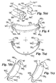
- Figure 5(a) shows an end view of a second embodiment of journal bearing arrangement 120 which forms a back-up bearing to a separately, magnetically, suspended shaft 10 described above.
- the back-up bearing arrangement 120 comprises a housing 124 of cylindrical form having a longitudinal axis 125 and enclosing a shaft space 126 which, in operation, is intended to contain separately suspended shaft 10 for rotation about a shaft axis 12 coincident with the housing axis 125.
- the housing part 124 may be a unitary body or, as illustrated, comprise upper and lower semi-circular components or shells 127 and 128 joined along a diametric interface 129, being lined internally by a ring of six arcuate bearing pads 130 1 - 130 6 spaced from each other in a circumferential direction about axis 125.
- the sliding bearing material may be a dry-running, lubricant filled sintered metal material as described above, or one requiring a fluid lubricant applied thereto as discussed below.
- Each pad 130 i is mounted with respect to the housing 124 by mounting means, indicated generally at 140, whereby the array of bearing pads define by the locus of their bearing surfaces the shaft space 126 such that with the shaft 10 in a desired operational disposition, that is, with the axes 12 and 125 coincident, the shaft surface is spaced radially from the bearing pad surface 136 i by a small gap, and furthermore the convex surface 134 i is separated radially from the housing surface.
- the mounting means 140 comprises pad stop means, indicated generally at 145, for limiting radially inward displacement of the bearing pads, that is, movement away from the housing surface.
- pad stop means indicated generally at 145, for limiting radially inward displacement of the bearing pads, that is, movement away from the housing surface.
- each pad 130 i has formed at its end regions 130' i and 130" i pad end shoulders 146' i and 146" i respectively, each shoulder having a surface 147' i and 147" i facing towards the shaft space and rebated with respect to the bearing surface and a further shoulder 148' i and 148" i facing away from the shaft space.
- Each shoulder such as 146" i , has associated therewith a pad stop, or restraining boss, 150 extending from the housing surface adjacent the pad end region and having a head portion 152 i disposed to overlie the shoulder to limit displacement of the bearing pad away from the housing surface by abutment with the shoulder surface 147" i but permit displacement of the bearing pad towards the housing surface, until limited by abutment with the shoulder futher surface 148" i .
- Each restraining boss is disposed between adjacent pads so that its head portion overlies at least one end shoulder of at least one adjacent pad; most practicably, and as shown, the boss is shared by adjacent pads. That is, the restraining boss 150 1 is disposed between the bearing pads 130 1 and 130 2 , restraining boss 150 2 is disposed between the bearing pads 130 2 and 130 3 and so on. Looked at another way, the bearing pad 130 2 has associated therewith a pair of restraining bosses 150 1 and 150 2 whose heads 152 1 and 152 2 overlie the shoulders 146' 2 and 146" 2 respectively.
- the mounting means 140 also comprises, associated with each pad 130 i , a support peg 160 i which has a shank 162 i extending substantially radially from a head 164 i that effects threaded engagement with a through aperture 166 i in the housing wall.
- Each said associated bearing pad has in its convex face 134 i a corresponding recess 168 i dimensioned to receive a protruding peg shank with a clearance permitting the pad to pivot and slide thereon.
- Each of the leaf springs has a substantially cylindrical curvature centred on the housing axis 125 and a natural radius of curvature substantially equal to that of the others whereby the springs are able to nest one within another and bear one on another in a radial direction to form a stack 171 effecting suspension of the associated bearing pads.
- the leaf springs are substantially flat in a direction axially of the housing and have a width substantially equal to that of the bearing pads so that there is a considerable area of face-to-face contact between them for load transmission.
- the stack comprises associated with each bearing pad, a first spring 172 A terminating adjacent one end region 130' 2 of the pad and pivotally secured thereto at shoulder 146' 2 , a second spring 172 B terminating adjacent the opposite end region of the pad and pivotally secured thereto at shoulder 146" 2 , and a third spring 172 C mounted at its centre on a spigot provided by the support peg 162 2 and particularly the shank 162 2 thereof.
- the third spring has a small clearance with respect to its mounting spigot, being constrained thereby to sliding motion along the spigot and constrained in respect of displacement from the housing surface by a spring stop 173 2 in the form of a nut positionable along the axis of the spigot to define the limit of displacement.
- the first and second springs have a greater clearance of the spigot so that it presents no impedance to their displacement relative to the housing and to each other.
- Each of the leaf springs 172 A and 172 B has, at its termination 172 A2 and 172 B2 adjacent a respective end region 130' 2 , 130" 2 of a bearing pad a width in an axial direction slightly greater than the end region and axially spaced, radially extending flanges 176 arranged to flank, and be secured to, the pad shoulders.
- the third spring may be considered as a primary spring whilst the first and second springs, secured to the pad, may be considered as secondary springs, and herein referred to as such.
- leaf springs there are the same number of leaf springs as there are bearing pads, that is, six, and the leaf springs are of substantially equal length.
- the leaf springs are arranged each to extend circumferentially and effect support for three adjacent circumferentially spaced bearing pads, each of said springs 172 A , 172 B and 172 C being offset circumferentially with respect to adjacent springs of the stack such that for each said bearing pad, say 130 2 , the associated first spring 172 A secured to said one end region 130' 2 comprises a third spring 172 C of the pad 130 3 spaced circumferentially in a direction towards said opposite end region 130" 2 of the bearing pad and the associated second spring 172 B secured to said opposite end 130" 2 comprises a third spring 172 C of the pad 130 1 spaced circumferentially in a direction towards said one end 130' 2 of the bearing pad. That is, in general for each bearing pad 130 i , the first and second springs associated with that pad comprise respectively the third springs of the adjacent circum
- the associated third spring 172 C extends circumferentially from its mounting spigot through an angle of approximately ⁇ 90°, that is, an included angle of 180°, the precise angle being dictated by the number and circumferential dimensions of bearing pads in the array and the number of bearing pads beneath which each spring extends, but preferably is within the range ⁇ (60 to 120)° for reasons discussed below.
- the restraining bosses are disposed so as to maintain each spigot-mounted third, primary, spring in tension with its ends splayed apart by abutment of the bearing pad shoulders to which the ends are secured with the heads of the restraining bosses, that is, the primary spring biases the shoulders against the restraining boss heads and insofar as all the springs are mounted and secured similarly, a substantially uniform, radially directed bias is exerted between each of the bearing pads and the adjacent restraining boss heads.
- each said leaf spring has, in the vicinity of a said aperture, strengthening means 174' comprising one or more flanges having components extending circumferentially and radially with respect to the shaft space (as best seen in Figure 5(c)).
- each restraining boss 150 i has its head portion define a cam surface and the associated pad end shoulder a co-operable cam follower permitting the shoulder to move radially and circumferentially with respect to the shaft space in abutment with the restraining boss and for the bearing pad to move according to similar or differential movements of the shoulders at opposite ends of the bearing pad.
- Each said boss 150 i has its head portion 152 i defined by a recess 175 open towards the adjacent pad and dimensioned to receive therein said pad end shoulder 146" i , said recess having a wall 176 generated about an axis 177 extending orthogonally to the circumferential and radial directions and defining a cam surface.
- the surface 147" i and further surface 148" i of the bearing pad end shoulder are also each generated about an axis,178' and 178" respectively, extending orthogonally to the circumferential radial direction as a convex cam follower arranged to permit, in abutment with the cam surface 176, translation and rotation relative thereto.
- the surface 147" i and further surface 148" i are, conveniently but not necessarily, contiguous and axes 178' and 178" coincident defining about a common axis 178, a substantially semi-cylindrical end region for the pad.
- cam and cam follower curvature results in a line contact which has a high loading tolerance but also a higherf riction level than may be acceptable, and, if desired, at least one of the cam follower and cam surfaces may be generated also about an axis such as 179', 179" or 179"' extending in at least one of the circumferential and radial directions to result in more of a point contact.
- the shaft suspension fails to maintain a gap between the rotating shaft and any bearing pad surface because the rotation axis is displaced from the housing axis in one particular direction the shaft may bear against a bearing pad, such as the exemplary pad 130 2 .
- a bearing pad such as the exemplary pad 130 2 .
- the various spring bias forces keeping the pad against the restraining boss heads 152 1 and 152 2 are overcome and the pad shoulder surfaces 147' i and 147" i are displaced radially with respect to the bosses, the displacement being resisted by the spring stack at least until the load reaches such a level that the pad end shoulder surfaces 148' i and 148" i abut the cam surface 176 (as shown ghosted).
- Such displacement causes the associated primary and secondary springs 172 A , 172 B and 172 C both to deflect relative to the housing and re-align their positions relative to each other by sliding.
- the load of the shaft is thus borne with resilience which prevents damage caused by impact between the shaft surface and bearing pad.
- deflection of the spring means by the deflected shaft includes storage of energy which is returned by the springs when the load is lessened.
- the return of energy from the spring means may cause problems if it is not damped.
- the mounting means 140 includes damping means, indicated generally at 180 and defined at least in part by the spring means 170, which is responsive to displacement of any particular bearing pad by rotation eccentricity of the shaft within the shaft space to reduce the return of energy from the spring means to the shaft substantially in phase with the eccentric rotation.
- the spring means 170 provides damping to impede the return of energy from the springs to the shaft in phase with the loading, the abutting faces of the stacked springs effecting friction orCoulomb damping by the above mentioned relative sliding of the spring surfaces during deflection.
- each primary spring is associated with secondary springs of several pads, it will be appreciated that the frictional damping occasioned by relative movement between springs is distributed circumferentially and not confined to the springs immediately between that pad and the housing.
- the mounting means 140 provides more than just friction, or Coulomb, damping
- the damping means 180 comprises coupling within the spring means between the stack of springs associated with the exemplary bearing pad 130 2 and bearing pads 130 1 and 130 3 spaced therefrom circumferentially about the shaft space, such that displacement of the bearing pad 130 2 in a direction towards the housing surface results in displacement of at least part of the circumferentially spaced bearing pads 130 1 and 130 3 away from the housing surface towards the shaft space and the rotating shaft therein.
- the primary spring extends for about 90° from its mounting spigot so that in the event of radial displacement of the pad 130 2 , the central region of the primary spring is also displaced and creates, at each end secured to an end shoulder of a circumferentially spaced bearing pad, a component of bias force acting substantially in the direction of said mounting spigot and operable to slide the cam follower surfaces of the circumferentially spaced pad end shoulders along the cam surfaces of the restraining bosses such that the proximal ends of the circumferentially spaced bearing pads are displaced by the cam surfaces away from the shaft space and the distal end of the circumferentially spaced bearing pads are displaced by the cam surfaces towards the shaft space such that a part of the bearing surface of that pad is tilted and displaced towards the shaft.
- Such circumferentially spaced displacement is arranged to bridge the gap to the eccentrically rotating shaft, resulting in the pad bearing against the shaft surface circumferentially spaced from where the shaft is applying load to the pad 130 2 , that is, applying a force to the shaft shifted in phase by about 90° from the load being applied to the pad 130 2 and better able to dampen any growth in the rotation eccentricity.
- a bearing arrangement similar to 120 may have eight bearing pads arrayed about the housing, each extending for approximately 45°; the primary spring associated with each may then extend through ⁇ 67.5° or ⁇ 112.5° in dependence on whether it extends beneath three or five adjacent pads. There may also be an odd number of bearing pads, say five, whereupon each primary spring may extend through ⁇ 108° to be associated with three adjacent pads.
- each such primary spring centred in line with any particular bearing pad may extend to be secured to the ends of non-adjacent pads and/or each said mounting spigot may be otherthqan in line with a particular pad but disposed between pads in the manner of the restraining bosses.
- Such variation of primary spring length thus gives considerable latitude in the number and extent of bearing pads employed.
- the resilience and friction damping may be varied for the whole bearing arrangement by suitable choice of materials and dimensions of the circumferentially extending springs which are each associated with a plurality of bearing pads, may be varied about the housing axis by employing springs with different behaviour, to offer maximum load bearing to the lowest pad in the housing for supporting the weight of the shaft, or may be varied for individual bearing pads by employing additional springs, stacked with the primary and secondary springs but not extending circumferentially beyond the associated pad.
- the level of friction which is a function of the overall contacting spring surface areas, may be controlled by choice of the number of surfaces and area of each.
- the back-up bearing is "dry-running" if the contacts between surfaces are such that there is a risk of the springs in the stack exhibiting stiction, generating excessive heat or even welding together, some or all of the spring surfaces may be provided with a lubricant or low-friction coating.
- the back-up bearing arrangements 20 and 120 each require a gap between shaft and bearing pad surface for normal operation in which the shaft is able to make movements within the control band of the magnetic, or other separate bearing suspension and not contact the back-up bearing pads.
- the design must compromise between the size of the gap is required for the back-up not to come into action too soon, but without letting an eccentrically rotating shaft acquire too much out-of-balance energy to be controlled by the back-up bearing when it does operate.
- the gap between the pads and shaft may usefully be reduced in proportion to the lack of confidence, to the extent of being eliminated in response to a detected inability of the shaft to be borne separately, that is, actual or incipient magnetic bearing failure.
- Figure 8(a) shows a shaft 10 magnetically suspended by an actively controlled electromagnetic bearing 5 of a generally known form comprising an array of electromagnet armature poles through which current is passed by magnet controller 7, defining a magnetic circuit with the shaft which they surround spaced from the shaft by an air-gap 8.
- a sensor 9 detects variations in the air gap and signals the magnet controller to vary the coil currents together or relative to each other.
- the Figure also shows in sectional elevation a third embodiment of journal bearing arrangement 220 which forms a back-up bearing arrangement to the magnetic bearing.
- the back-up bearing arrangement shares many components with the arrangement 120 and these are given the same reference numbers and not described again in any detail. Other components above have substantial correspondence with those described above and in general, have numbers with a leading "2".
- the back-up bearing is arrangement is distinguished principally by the inclusion of back-up control means 282 operable to determine the level of separate support for the shaft and to vary the operating gap between the bearing pads and shaft by means of the pad stop means 245 as a function of confidence in said level of separate support, the pad stop means being displaceable relative to the housing surface so as to vary the magnitude of the operating gap.
- the pad stop means comprises between each pair of adjacent bearing pads, such as 130 1 and 130 2 a restraining boss such as 250 1 which has a head 152 1 recessed to accommodate and effect restraining abutment with shoulders at the end regions of the pads.
- a restraining boss such as 250 1 which has a head 152 1 recessed to accommodate and effect restraining abutment with shoulders at the end regions of the pads.
- the comparable restraining boss 150 1 is fixed to the housing
- the restraining boss 250 1 and each other boss 250i, is mounted on a column 253 1 and, within a mounting bush 253' 1' translatable relative to the housing along a radial axis.
- the back-up control means 282 further comprises actuation means 283 coupled to the columns of the restraining bosses to effect radial translation of said restraining bosses simultaneously, taking the form of ring means 284 extending circumferentially about the hosing and axially displaced from, but adjacent to, the array of restraining boss columns and mechanical coupling means 285 between each said boss column and the ring operable to transfer circumferential rotation of the ring into radial motion of each said restraining boss.
- the ring means comprises a pair of substantially flat annular rings 284 A , 284 B sandwiching the restraining boss columns of the array and the mechanical coupling means comprises an axial projection from one to the other engageable in a slot inclined with respect to the circumferential and radial directions, forming a cam and cam follower pair whereby displacement of the ring in one circumferential direction effects displacement of all of the restraining bosses in one radial direction.
- the axial projection is formed by a bolt 285' extending, along an axis parallel to housing axis 125, through the column 253 and slots 286 A , 286 B respectively in each of the adjacent rings 284 A , 284 B . It will be seen that the ring means 284 is supported with respect to the housing means by said mechanical coupling with the individual restraining bosses.
- the actuation means 283 further comprises a relatively reciprocable piston and cylinder arrangement 287, operably coupled tangentially to the rings of the ring means at 287' to effect a rotational motion of the ring means circumferentially with respect to the housing, as well as a controller circuit 288 which is arranged to receive signals from the magnetic bearing air gap sensor 9 and, by comparison with pre-programmed or "learned" relationships between air gap variation and lack of magnetic bearing control stored in memory 288', to provide an actuating signal to the piston and cylinder arrangement 287, to effect rotation of the ring means and drive the pad stop restraining bosses radially inwardly such that the back-up bearing pads contact the shaft surface or at least reduce the distance it has to displace to become supported.
- a controller circuit 288 which is arranged to receive signals from the magnetic bearing air gap sensor 9 and, by comparison with pre-programmed or "learned" relationships between air gap variation and lack of magnetic bearing control stored in memory 288', to provide an actuating signal to
- the back up bearing pads may be moved towards the shaft surface in case it does fail, but not contact the shaft until then. However if failure of the magnetic bearing is detected, possibly directly from magnet controller 7, the back-up bearing controller may displace the bearing pads to contact the shaft without delay.
- the external control as provided by the back-up control means may be employed with fluid supply means, indicated at 290, and including ducts 292 through the pads, to provide lubricant when the bearing pads are moved to contact the shaft.
- the bearing pad material need not be dry-lubricated and may be of any suitable material that requires a separately supplied lubricant or a of non-lubricated material that requires a coolant.
- ducts such as 292 may be employed when the pads are retracted away from the shaft to admit a gas to effect cooling and/or gas damping in addition to the friction and spring damping, and such ducts and cooling gas may be employed with the bearing arrangement 120 in like manner, although not specifically illustrated.
- piston and cylinder arrangement 287 may supply a pulsating force to effect shaft contact periodically to enhance damping, and insofar as the restraining bosses are translatable by an externally applied force, they also react against it and to this end the fluid circuit of the piston and cylinder arrangement may effect additional resilience and/or damping of any periodic elements of such reaction in line with the shaft displacement but effecting also control by other bearing pads at circumferential positions out of phase with such displacement.
- the construction of the second embodiment 120 may be employed as a primary support bearing by omission of the gap, the resilient mounting of the pads and circumferential linking being able to provide damping in response to rotation eccentricity of the shaft.
- the stop means 145 takes the form of inter-pad restraining bosses recessed such that the pad end shoulders 146' i and 146" i effect abutment therewith to define limits of displacement both away from and towards the housing surface, that is, by way of shoulder surface 147' i 47" i and further surface 148' i , 148" i respectively. It will be appreciated that insofar as bearing pads are each mounted, albeit loosely, upon a spring mounting spigot 160 i , such spigot may effect limiting of displacement towards the housing surface, as many abutment of the pad and underlying spring stack.
- each bearing pad 130 i may have its shoulder region 146' i with only one cam follower surface 147' i , 147" i .
Landscapes
- Engineering & Computer Science (AREA)
- General Engineering & Computer Science (AREA)
- Mechanical Engineering (AREA)
- Physics & Mathematics (AREA)
- Fluid Mechanics (AREA)
- Support Of The Bearing (AREA)
- Sliding-Contact Bearings (AREA)
- Vibration Prevention Devices (AREA)
- Golf Clubs (AREA)
- Shafts, Cranks, Connecting Bars, And Related Bearings (AREA)
Claims (23)
- Agencement de palier lisse (20, 120, 220) pour un arbre rotatif (10), comprenant(i) un moyen de carter (24, 124, 224) agencé pour entourer un espace d'arbre (26, 126) et comportant une surface de carter (35) orientée vers l'espace d'arbre,(ii) une pluralité de coussinets de palier courbés (30i, 130i) disposés autour de l'espace d'arbre en recouvrant la surface du carter, chacun ayant une face de palier (36i, 136i) adjacente à l'espace d'arbre et une face de corps (34i, 134i) adjacente à la surface du carter, et(iii) un moyen de montage (40, 140, 240) agencé pour supporter au moins un coussinet de palier par rapport à la surface du carter, mobile par rapport à celui-ci dans un sens allant vers et partant de la surface du carter, comprenant associé à chaque dit coussinet mobile,
un moyen d'arrêt (45, 145, 245) comprenant une protubérance de retenue (50, 150) et un épaulement (46, 146, 69'), procurés chacun par le carter et le coussinet de palier, ladite protubérance comportant une partie de tête (52, 152, 64') agencée pour recouvrir l'épaulement afin de limiter l'étendue du mouvement d'écart du coussinet de la surface du carter et permettre le déplacement du coussinet de palier vers la surface du carter, et
un moyen de ressort, pouvant être mis en oeuvre pour solliciter le coussinet à s'écarter de la surface du carter vers la limite imposée par le moyen d'arrêt et exercer sur ledit coussinet arrêté un niveau prédéterminé de précharge et, en réponse à la charge appliquée sur la surface d'appui dépassant ledit niveau de précharge, permettre le déplacement du coussinet vers la surface du carter. - Agencement de palier lisse selon la revendication 1, dans lequel le moyen de ressort (70, 170) comprend une pluralité d'éléments élastiques pouvant être fléchis individuellement (72, 172).
- Agencement de palier lisse selon la revendication 2, dans lequel le moyen de montage (140) comprend, associée à au moins un dit coussinet de palier mobile (30i), au moins une clavette de support (60, 60', 60") fixée à une première extrémité de la clavette par rapport à l'un du coussinet et du carter et comportant une tige (62, 62', 62") s'étendant vers une extrémité non fixée de la clavette libre de se déplacer par rapport à l'autre extrémité du coussinet ou du palier, ledit moyen de ressort (70) comprend au moins un empilement (71) d'éléments élastiques pouvant être fléchis individuellement (72) agencés pour porter les uns sur les autres dans une direction radiale, disposés dans un état de compression entre un coussinet ou palier et l'autre du coussinet ou du palier, ou bien de la clavette de support fixée sur ceux-ci, au moins un dit empilement d'éléments élastiques étant muni d'une ouverture et étant associé à une cheville de support, disposée dans une relation coaxiale avec la tige de celle-ci.
- Agencement de palier lisse selon la revendication 2 ou la revendication 3, dans lequel les éléments pouvant être fléchis individuellement comprennent des ressorts à rondelles embouties annulaires (72) et le moyen de ressort comprend au moins un empilement (71) desdits ressorts à rondelles embouties annulaires.
- Palier lisse selon la revendication 2, dans lequel les éléments élastiques pouvant être fléchis individuellement (172) comprennent des ressorts à lames (172A, 172B, 172C) s'étendant circonférentiellement par rapport au carter et à l'espace d'arbre, et le moyen de ressort comprend, associé à chaque coussinet de palier entre le coussinet et la surface de carter, un empilement (171) desdits ressorts à lames agencés pour porter les uns sur les autres dans une direction radiale.
- Palier lisse selon la revendication 5, dans lequel ledit empilement (171) comprend associé à chaque coussinet de palier (130i) au moins un premier ressort (172A) se terminant de manière adjacente à une région d'extrémité du coussinet et fixé de manière pivotante à celui-ci, un second ressort (172B) se terminant de manière adjacente à la région d'extrémité opposée du coussinet et fixé de manière pivotante à celui-ci, et un troisième ressort (172c) monté au niveau de son centre sur une broche (160i) s'étendant le long d'un axe radial et contraint par la broche à un mouvement de glissement le long de la broche et par rapport au déplacement depuis la surface du carter.
- Agencement de palier lisse selon la revendication 6, dans lequel chacun des ressorts à lames empilés (172A, 172B, 172C) présente une courbure sensiblement cylindrique centrée sur l'axe du carter (125) et sensiblement égale à celle des autres, grâce à quoi les ressorts qui se chevauchent circonférentiellement peuvent s'empiler en étant imbriqués les uns dans les autres.
- Agencement de palier lisse selon la revendication 7, dans lequel les ressorts à lames associés auxdits coussinets de palier sont agencés chacun pour s'étendre circonférentiellement par rapport au carter et à l'espace d'arbre et assurer un support pour au moins trois coussinets de palier espacés circonférentiellement, adjacents les uns aux autres, chacun desdits ressorts étant décalé circonférentiellement par rapport aux ressorts adjacents de l'empilement de sorte que, pour chaque dit coussinet de palier (1302), le premier ressort associé (172A) fixé à ladite première région d'extrémité comprend un troisième ressort d'un coussinet (1303) espacé circonférentiellement dans une direction vers ladite région d'extrémité opposée du coussinet de palier et le second ressort associé (172B) fixé à ladite extrémité opposée comprend un troisième ressort d'un coussinet (1301) espacé circonférentiellement dans une direction vers ladite première extrémité du coussinet de palier.
- Agencement de palier lisse selon la revendication 7 ou la revendication 8, dans lequel pour chaque dit coussinet de palier (1302), le troisième ressort associé (172C) s'étend depuis son tourillon de montage sur un angle dans la plage de ± (60 à 120°).
- Agencement de palier lisse selon l'une quelconque des revendications 7 à 9, dans lequel les premier et second ressorts (172A, 172B) associés à un dit coussinet de palier (1302) comprennent respectivement les troisièmes ressorts des coussinets de palier adjacents espacés circonférentiellement (1301, 1303).
- Agencement de palier lisse selon l'une quelconque des revendications 7 à 10, dans lequel le moyen d'arrêt (145, 245) associé à chaque dit coussinet de palier mobile (130i) comprend au moins une paire d'épaulements (146'i, 146"i) espacés aux extrémités opposées du coussinet de palier dans la direction circonférentielle, chaque épaulement présentant une surface (147'i, 147"i) tournée vers l'espace d'arbre et réduite par rapport à la surface d'appui, et associée à chaque dit épaulement, une dite protubérance de retenue (150i) disposée avec la partie de tête (152i) agencée pour recouvrir un épaulement d'extrémité d'au moins un coussinet adjacent et où au moins une dite protubérance de retenue traverse une ouverture (174) dans chaque ressort à lame s'étendant circonférentiellement entre les coussinets de palier espacés et chaque dit ressort à lame comporte, au voisinage de ladite ouverture, un moyen de renforcement (174') pour maintenir le fléchissement du ressort dans les limites élastiques.
- Agencement de palier lisse selon l'une quelconque des revendications 7 à 11, dans lequel chaque tourillon comprend un élément d'arrêt de ressort pouvant être positionné axialement (1732) pour définir la limite de déplacement du troisième ressort radialement par rapport à la surface du carter, le moyen d'arrêt (145 ; 245) associé à chaque dit coussinet de palier mobile (130i) comprend au moins une paire d'épaulements (146'i, 146"i) espacés aux extrémités opposées du coussinet de palier dans la direction circonférentielle, chaque épaulement ayant une surface (147'i, 147"i) tournée vers l'espace d'arbre et réduite par rapport à la surface d'appui, et associée à chaque dit épaulement, une dite protubérance de retenue (150i) disposée avec la partie de tête agencée pour recouvrir un épaulement d'extrémité d'au moins un coussinet adjacent, et dans lequel les protubérances de retenue (1503, 1506) sont disposées de façon à maintenir chaque ressort monté sur une broche (172C) en tension, ses extrémités étant écartées en étant séparées par la butée des épaulements de coussinets de palier (146"3, 146'1), au niveau desquels les extrémités desdits ressorts sont fixées au coussinet, avec les têtes des protubérances de retenue.
- Agencement de palier lisse selon la revendication 12, dans lequel la partie de tête (152i) de chaque protubérance de retenue définit une surface de came (176) et l'épaulement (146"i) d'extrémité de coussinet associé définit une contre-came pouvant coopérer avec celle-ci, permettant à l'épaulement de se déplacer radialement et circonférentiellement par rapport à l'espace d'arbre en butée avec la protubérance de retenue et pour que le coussinet de palier bascule en résultat du déplacement différentiel entre les épaulements aux extrémités opposées du coussinet de palier.
- Agencement de palier lisse selon la revendication 13, dans lequel le moyen de montage comprend un moyen d'amortissement (180) comprenant une liaison à l'intérieur du moyen de ressort (170) entre l'empilement (171) de ressorts s'étendant circonférentiellement (172A, 172B, 172C) associés à un dit coussinet de palier (1302) et au moins un coussinet de palier (1303, 1301) espacé de celui-ci circonférentiellement autour de l'espace d'arbre, grâce à quoi chaque coussinet de palier, en réponse à l'application d'une force sur le coussinet de palier supérieure à la force de sollicitation exercée sur celui-ci par l'empilement de ressorts, peut être déplacé avec les ressorts de l'empilement vers le carter jusqu'à être retenu par une butée, et le déplacement du troisième ressort (172C) de l'empilement crée, à chaque extrémité du troisième ressort fixé à un épaulement d'extrémité d'un coussinet de palier espacé circonférentiellement (1301, 1303), une composante d'une force de sollicitation agissant sensiblement dans la direction dudit déplacement et pouvant être mise en oeuvre pour faire glisser les surfaces de contre-came (147'3, 147"3 ; 147'1, 147"1) des épaulements d'extrémité de coussinets espacés circonférentiellement le long de la surface de came (176) de la protubérance de retenue respective de sorte que l'extrémité distale du coussinet de palier espacé circonférentiellement (130"3) est déplacée par la surface de came vers l'espace d'arbre de sorte qu'une partie de la surface d'appui (1363) de ce coussinet est basculée et déplacée vers l'espace d'arbre.
- Agencement de palier lisse selon la revendication 7, dans lequel le moyen de montage comprend un moyen d'amortissement (180) comprenant une liaison à l'intérieur du moyen de ressort (170) entre l'empilement (171) de ressorts s'étendant circonférentiellement (172A, 172B, 172C) associés à un dit coussinet de palier (1302) et à au moins un coussinet de palier (1303, 1301) espacé de celui-ci circonférentiellement autour de l'espace d'arbre, grâce à quoi le déplacement d'un dit coussinet de palier dans une direction vers la surface du carter résulte en un écartement d'au moins une partie d'un dit coussinet de palier espacé circonférentiellement par rapport à la surface du carter vers l'espace d'arbre.
- Agencement de palier lisse selon l'une quelconque des revendications précédentes, dans lequel le moyen de montage comprend un moyen d'amortissement (80 ; 180) défini par le moyen de ressort (70 ; 170) sensible à un déplacement d'un coussinet de palier particulier quelconque du fait d'une excentricité de rotation de l'arbre à l'intérieur de l'espace d'arbre afin de réduire le retour d'énergie depuis le moyen de ressort vers l'arbre sensiblement en phase avec la rotation excentrée.
- Agencement de palier lisse selon la revendication 16, dans lequel le moyen d'amortissement (180) comprend un moyen d'amortissement à friction pouvant être mis en oeuvre pour effectuer un amortissement par effet Coulomb entre des surfaces en butée et patinant relativement du moyen de ressort.
- Agencement de palier lisse selon l'une quelconque des revendications 14 à 17, dans lequel le moyen d'amortissement (80 ; 180) est agencé pour fournir un amortissement différent à des positions circonférentielles différentes autour de l'espace d'arbre.
- Agencement de palier lisse selon l'une quelconque des revendications précédentes, dans lequel le moyen de ressort (70 ; 170) est agencé pour fournir au moins l'une d'une raideur et d'une précharge du ressort variant en fonction de la position du coussinet autour de l'espace d'arbre.
- Agencement de palier lisse selon l'une quelconque des revendications précédentes, dans lequel le moyen d'arrêt (45 ; 145 ; 245) associé à chaque dit coussinet de palier mobile (30i ; 130i) comprend au moins une paire d'épaulements (46'i, 46"i, 146'i, 146"i) espacés au niveau des bords opposés du coussinet, chaque épaulement présentant une surface (47'i, 47"i ; 147'i, 147"i) tournée vers l'espace d'arbre et réduite par rapport à la surface d'appui, et associée à chaque dit épaulement, une dite protubérance de retenue (50i ; 150i) s'étendant depuis la surface du carter adjacente audit bord du coussinet comportant une partie de tête (52i ; 152i) disposée pour recouvrir l'épaulement.
- Palier lisse de secours pour un arbre supporté séparément (10) comprenant un agencement de palier lisse (20 ; 120 ; 220) selon l'une quelconque des revendications précédentes, comportant une pluralité de coussinets de palier arqués (30i, 130i), sollicités chacun par le moyen de ressort associé (70i ; 170i) contre le moyen d'arrêt (45 ; 145 ; 245) et définissant par le biais du lieu géométrique de leurs surfaces de palier (36i ; 136i) un espace d'arbre (26 ; 126) ayant des dimensions de section transversale supérieures à celles de l'arbre devant y être contenu pour définir au cours de la rotation de l'arbre un écartement fonctionnel (42i) correspondant à un degré permis d'écart de position de l'arbre par rapport à la concentricité avec l'espace d'arbre.
- Agencement de palier lisse de secours selon la revendication 21, dans lequel le moyen d'arrêt (245) peut être déplacé radialement par rapport à la surface du carter de manière à faire varier l'importance de l'écartement fonctionnel.
- Agencement de palier lisse de secours selon la revendication 22, comprenant un moyen de commande de secours (232) pouvant être mis en oeuvre pour déterminer le niveau du support séparé pour l'arbre et pour faire varier l'écartement fonctionnel grâce au moyen d'arrêt (245) en fonction du degré de confiance dans ledit niveau du support séparé.
Applications Claiming Priority (5)
| Application Number | Priority Date | Filing Date | Title |
|---|---|---|---|
| US29634501P | 2001-06-06 | 2001-06-06 | |
| US296345P | 2001-06-06 | ||
| GB0115336 | 2001-06-22 | ||
| GBGB0115336.0A GB0115336D0 (en) | 2001-06-22 | 2001-06-22 | Bearing |
| PCT/GB2002/002399 WO2002099294A2 (fr) | 2001-06-06 | 2002-06-06 | Agencement de palier pour portee d'arbre |
Publications (2)
| Publication Number | Publication Date |
|---|---|
| EP1392984A2 EP1392984A2 (fr) | 2004-03-03 |
| EP1392984B1 true EP1392984B1 (fr) | 2006-02-08 |
Family
ID=26246231
Family Applications (1)
| Application Number | Title | Priority Date | Filing Date |
|---|---|---|---|
| EP02730441A Expired - Lifetime EP1392984B1 (fr) | 2001-06-06 | 2002-06-06 | Agencement de palier pour portee d'arbre |
Country Status (9)
| Country | Link |
|---|---|
| US (1) | US7367713B2 (fr) |
| EP (1) | EP1392984B1 (fr) |
| JP (1) | JP4121947B2 (fr) |
| AT (1) | ATE317505T1 (fr) |
| AU (1) | AU2002302762A1 (fr) |
| CA (1) | CA2447143C (fr) |
| DE (1) | DE60209117D1 (fr) |
| RU (1) | RU2293226C2 (fr) |
| WO (1) | WO2002099294A2 (fr) |
Cited By (1)
| Publication number | Priority date | Publication date | Assignee | Title |
|---|---|---|---|---|
| WO2023046947A1 (fr) | 2021-09-27 | 2023-03-30 | Voith Patent Gmbh | Palier radial à patins oscillants et ensemble arbre |
Families Citing this family (35)
| Publication number | Priority date | Publication date | Assignee | Title |
|---|---|---|---|---|
| US7497628B2 (en) * | 2003-06-07 | 2009-03-03 | Siemens Aktiengesellschaft | Tilt pad bearing assembly |
| GB2424043A (en) * | 2005-03-12 | 2006-09-13 | Siemens Ind Turbomachinery Ltd | A tilting pad bearing assembly |
| DE102006019873B3 (de) * | 2006-04-28 | 2007-10-18 | Siemens Ag | Fanglager für eine elektrische Maschine sowie elektrische Maschine mit zumindest einem derartigen Fanglager |
| US8678658B2 (en) | 2007-04-13 | 2014-03-25 | Waukesha Bearings Corporation | Tilting pad bearing |
| US8408802B2 (en) * | 2009-06-08 | 2013-04-02 | Waukesha Bearings Corporation | Bi-directional rotation offset pivot thrust bearing |
| US8845196B2 (en) | 2007-04-13 | 2014-09-30 | Jongsoo Kim | Compliant bearing |
| US10808756B2 (en) | 2007-04-13 | 2020-10-20 | Waukesha Bearings Corporation | Compliant bearing |
| EP2154386A1 (fr) | 2008-08-11 | 2010-02-17 | Siemens Aktiengesellschaft | Support de palier avec un palier radial magnétique fendu et un palier d'arrêt fendu dans un logement de palier commun fendu |
| DE102008051446B3 (de) * | 2008-10-13 | 2010-05-27 | Siemens Aktiengesellschaft | Fanglager eines Magnetlagers oder Luftlagers |
| DE102009031887B4 (de) * | 2009-07-06 | 2012-06-06 | Siemens Aktiengesellschaft | Fanglager zum Auffangen einer Rotorwelle einer Maschine |
| US20110052109A1 (en) * | 2009-08-28 | 2011-03-03 | Dresser-Rand Company | Hydrostatic auxiliary bearing for a turbomachine |
| IT1395716B1 (it) * | 2009-09-22 | 2012-10-19 | Nuovo Pignone Spa | Cuscinetto, meccanismo di fissaggio e metodo per fissare almeno un pattino. |
| IT1395717B1 (it) * | 2009-09-22 | 2012-10-19 | Nuovo Pignone Spa | Cuscinetto, meccanismo di distribuzione olio e metodo. |
| EP2486292B1 (fr) * | 2009-10-09 | 2017-08-09 | Dresser-Rand Company | Système de palier auxiliaire destiné à un système de rotor sur support magnétique |
| US8283825B2 (en) * | 2009-10-09 | 2012-10-09 | Dresser-Rand Company | Auxiliary bearing system with plurality of inertia rings for magnetically supported rotor system |
| WO2011044430A2 (fr) * | 2009-10-09 | 2011-04-14 | Dresser-Rand Company | Système de palier auxiliaire à réservoir d'huile pour un système de rotor sur support magnétique |
| EP2486295B1 (fr) * | 2009-10-09 | 2018-03-14 | Dresser-Rand Company | Système de palier auxiliaire à bague de lubrification pour système de rotor à support magnétique |
| WO2011088004A2 (fr) | 2010-01-15 | 2011-07-21 | Dresser-Rand Company | Système de support et d'ajustement d'ensemble palier |
| AT509625B1 (de) * | 2010-04-14 | 2012-02-15 | Miba Gleitlager Gmbh | Lagerelement |
| DE102010054106A1 (de) * | 2010-12-10 | 2012-06-14 | Voith Patent Gmbh | Radiallager zum Lagern einer Welle |
| WO2013109235A2 (fr) | 2010-12-30 | 2013-07-25 | Dresser-Rand Company | Procédé de détection en ligne de défauts de résistance à la masse dans des systèmes de palier magnétique actif |
| US8994237B2 (en) | 2010-12-30 | 2015-03-31 | Dresser-Rand Company | Method for on-line detection of liquid and potential for the occurrence of resistance to ground faults in active magnetic bearing systems |
| WO2012138545A2 (fr) | 2011-04-08 | 2012-10-11 | Dresser-Rand Company | Système de refroidissement à circulation d'huile diélectrique pour paliers enfermés et dispositifs électroniques enfermés |
| WO2012166236A1 (fr) * | 2011-05-27 | 2012-12-06 | Dresser-Rand Company | Roulement segmenté à décélération en roue libre pour des systèmes de roulement magnétique |
| US8851756B2 (en) | 2011-06-29 | 2014-10-07 | Dresser-Rand Company | Whirl inhibiting coast-down bearing for magnetic bearing systems |
| WO2013031106A1 (fr) * | 2011-09-02 | 2013-03-07 | 株式会社ナップワン | Dispositif d'assistance de rotation, procédé d'assistance de rotation et dispositif générateur d'électricité |
| EP2623800A1 (fr) * | 2012-01-31 | 2013-08-07 | Technische Universität Darmstadt | Palier lisse |
| JP2015533410A (ja) * | 2012-11-08 | 2015-11-24 | ワウケシャ ベアリングズ コーポレーションWaukesha Bearings Corporation | ハイブリッド軸受 |
| US10184511B2 (en) | 2013-01-11 | 2019-01-22 | United Technologies Corporation | Linkage with spherical or journal bearing assembly |
| CN104912925A (zh) * | 2014-03-10 | 2015-09-16 | 重庆永进重型机械成套设备有限责任公司 | 一种可倾瓦滑动轴承 |
| CN104806631B (zh) * | 2015-03-01 | 2017-08-08 | 北京航空航天大学 | 一种用于磁悬浮高速旋转设备的径轴一体柔性保护轴承 |
| CN108953377B (zh) * | 2018-08-22 | 2019-11-08 | 合肥工业大学 | 一种面向可重复使用火箭涡轮泵的液磁复合轴承 |
| JP7231437B2 (ja) * | 2019-02-20 | 2023-03-01 | 三菱重工業株式会社 | 油浴型軸受装置及び回転機械 |
| ES2933816T3 (es) * | 2019-05-16 | 2023-02-14 | Siemens Gamesa Renewable Energy As | Disposición de cojinetes para una turbina eólica y turbina eólica |
| EP3904711A1 (fr) * | 2020-04-28 | 2021-11-03 | Siemens Gamesa Renewable Energy A/S | Procédé de remplacement d'un patin coulissant d'un palier coulissant rotatif, palier lisse et éolienne |
Family Cites Families (13)
| Publication number | Priority date | Publication date | Assignee | Title |
|---|---|---|---|---|
| FR1475790A (fr) * | 1966-02-09 | 1967-04-07 | Rateau Soc | Perfectionnement aux paliers et butées à gaz de machines tournantes |
| JPS5324625Y2 (fr) | 1974-01-24 | 1978-06-23 | ||
| US3944300A (en) | 1975-02-26 | 1976-03-16 | Bucyrus-Erie Company | Resilient guide bushing mounting for blast hole drills or the like |
| JPS59175619A (ja) | 1983-03-22 | 1984-10-04 | Hitachi Ltd | 動圧気体軸受 |
| JPS60196425A (ja) | 1984-03-16 | 1985-10-04 | Daido Metal Kogyo Kk | 軸受すきまを一定に維持されたパツド型ジヤ−ナル軸受装置 |
| DE3622495A1 (de) * | 1986-07-02 | 1988-01-21 | Mannesmann Ag | Saeulenfuehrung, insbesondere an schmiedepressen |
| US5421655A (en) | 1987-05-29 | 1995-06-06 | Kmc, Inc. | Fluid dampened support having variable stiffness and damping |
| DE3815029A1 (de) * | 1988-05-03 | 1989-11-16 | Interatom | Gasstatisches lager mit geteilter lagerschale |
| GB2268983B (en) | 1992-07-23 | 1996-04-03 | Glacier Metal Co Ltd | Magnetic bearing back-up |
| RU2073133C1 (ru) * | 1992-08-26 | 1997-02-10 | Акционерное общество "Камский автомобильный завод" | Адаптивная опора скольжения |
| US5714818A (en) | 1994-10-18 | 1998-02-03 | Barber-Colman Company | Backup bearing for magnetic bearings |
| GB2325029B (en) * | 1997-05-07 | 2000-08-30 | Glacier Metal Co Ltd | Tilting pad thrust bearing arrangement |
| GB9818098D0 (en) * | 1998-08-19 | 1998-10-14 | Corac Group Plc | Improvements in or relating to bearings |
-
2002
- 2002-06-06 US US10/479,583 patent/US7367713B2/en not_active Expired - Lifetime
- 2002-06-06 DE DE60209117T patent/DE60209117D1/de not_active Expired - Lifetime
- 2002-06-06 EP EP02730441A patent/EP1392984B1/fr not_active Expired - Lifetime
- 2002-06-06 RU RU2004100103/11A patent/RU2293226C2/ru not_active IP Right Cessation
- 2002-06-06 WO PCT/GB2002/002399 patent/WO2002099294A2/fr not_active Ceased
- 2002-06-06 JP JP2003502383A patent/JP4121947B2/ja not_active Expired - Fee Related
- 2002-06-06 AT AT02730441T patent/ATE317505T1/de not_active IP Right Cessation
- 2002-06-06 CA CA2447143A patent/CA2447143C/fr not_active Expired - Fee Related
- 2002-06-06 AU AU2002302762A patent/AU2002302762A1/en not_active Abandoned
Cited By (2)
| Publication number | Priority date | Publication date | Assignee | Title |
|---|---|---|---|---|
| WO2023046947A1 (fr) | 2021-09-27 | 2023-03-30 | Voith Patent Gmbh | Palier radial à patins oscillants et ensemble arbre |
| DE102021124856A1 (de) | 2021-09-27 | 2023-03-30 | Voith Patent Gmbh | Kippsegmentradiallager und Wellenanordnung |
Also Published As
| Publication number | Publication date |
|---|---|
| WO2002099294A3 (fr) | 2003-06-12 |
| US7367713B2 (en) | 2008-05-06 |
| JP4121947B2 (ja) | 2008-07-23 |
| JP2004527714A (ja) | 2004-09-09 |
| WO2002099294A2 (fr) | 2002-12-12 |
| ATE317505T1 (de) | 2006-02-15 |
| CA2447143A1 (fr) | 2002-12-12 |
| CA2447143C (fr) | 2010-10-19 |
| DE60209117D1 (de) | 2006-04-20 |
| RU2293226C2 (ru) | 2007-02-10 |
| EP1392984A2 (fr) | 2004-03-03 |
| US20040240759A1 (en) | 2004-12-02 |
| AU2002302762A1 (en) | 2002-12-16 |
| RU2004100103A (ru) | 2005-02-27 |
Similar Documents
| Publication | Publication Date | Title |
|---|---|---|
| EP1392984B1 (fr) | Agencement de palier pour portee d'arbre | |
| US7611286B2 (en) | Journal bearing arrangement | |
| US5752774A (en) | Zero clearance auxiliary bearing for providing rotor shock tolerance | |
| US5215384A (en) | Self-centering squeeze film damper bearing | |
| EP1957758B1 (fr) | Ensemble comprenant un carter de palier de turbocompresseur et un palier semi-flottant | |
| US6582125B1 (en) | Smart foil journal bearing with piezoelectric actuators | |
| US4872767A (en) | Bearing support | |
| CA2157650C (fr) | Palier de reserve pour paliers magnetiques | |
| US5938344A (en) | Temperature compensating bearing | |
| US5021697A (en) | Auxiliary bearing design for active magnetic bearings | |
| US8926188B2 (en) | Compliant bearing mount | |
| US5651616A (en) | Tapered bearing housing | |
| CA2252906A1 (fr) | Systeme amortisseur a film comprime porte par un ressort suspendu pour paliers d'arbres | |
| US6527446B2 (en) | Foil journal bearing utilizing semi-active dampers | |
| US5397183A (en) | Active bearing | |
| JPH0727132A (ja) | ジャーナル軸受 | |
| ZA200308962B (en) | Journal bearing arrangement. | |
| EP0665545B1 (fr) | Anneau antichoc de butée d'arrêt pour la protection du palier de moteur d'entraínement de disque | |
| US8106556B2 (en) | Emergency rolling bearing that is insensitive to axial load | |
| US6467587B2 (en) | Energy absorbing shock mechanism for reducing impact and rotary actuator incorporating same | |
| JP2000002243A (ja) | 静圧空気軸受装置 | |
| CN117307616B (zh) | 着陆轴承组件及旋转机械设备 | |
| KR101187898B1 (ko) | 에어 포일 베어링의 충격 감쇠 시스템 | |
| KR20190114087A (ko) | 간극과 형상이 조절 가능한 베어링 | |
| JPH0210819Y2 (fr) |
Legal Events
| Date | Code | Title | Description |
|---|---|---|---|
| PUAI | Public reference made under article 153(3) epc to a published international application that has entered the european phase |
Free format text: ORIGINAL CODE: 0009012 |
|
| 17P | Request for examination filed |
Effective date: 20031119 |
|
| AK | Designated contracting states |
Kind code of ref document: A2 Designated state(s): AT BE CH CY DE DK ES FI FR GB GR IE IT LI LU MC NL PT SE TR |
|
| AX | Request for extension of the european patent |
Extension state: AL LT LV MK RO SI |
|
| GRAP | Despatch of communication of intention to grant a patent |
Free format text: ORIGINAL CODE: EPIDOSNIGR1 |
|
| GRAS | Grant fee paid |
Free format text: ORIGINAL CODE: EPIDOSNIGR3 |
|
| GRAA | (expected) grant |
Free format text: ORIGINAL CODE: 0009210 |
|
| AK | Designated contracting states |
Kind code of ref document: B1 Designated state(s): AT BE CH CY DE DK ES FI FR GB GR IE IT LI LU MC NL PT SE TR |
|
| PG25 | Lapsed in a contracting state [announced via postgrant information from national office to epo] |
Ref country code: FI Free format text: LAPSE BECAUSE OF FAILURE TO SUBMIT A TRANSLATION OF THE DESCRIPTION OR TO PAY THE FEE WITHIN THE PRESCRIBED TIME-LIMIT Effective date: 20060208 Ref country code: AT Free format text: LAPSE BECAUSE OF FAILURE TO SUBMIT A TRANSLATION OF THE DESCRIPTION OR TO PAY THE FEE WITHIN THE PRESCRIBED TIME-LIMIT Effective date: 20060208 Ref country code: BE Free format text: LAPSE BECAUSE OF FAILURE TO SUBMIT A TRANSLATION OF THE DESCRIPTION OR TO PAY THE FEE WITHIN THE PRESCRIBED TIME-LIMIT Effective date: 20060208 |
|
| REG | Reference to a national code |
Ref country code: GB Ref legal event code: FG4D |
|
| REG | Reference to a national code |
Ref country code: CH Ref legal event code: EP |
|
| REG | Reference to a national code |
Ref country code: IE Ref legal event code: FG4D |
|
| REF | Corresponds to: |
Ref document number: 60209117 Country of ref document: DE Date of ref document: 20060420 Kind code of ref document: P |
|
| PG25 | Lapsed in a contracting state [announced via postgrant information from national office to epo] |
Ref country code: DK Free format text: LAPSE BECAUSE OF FAILURE TO SUBMIT A TRANSLATION OF THE DESCRIPTION OR TO PAY THE FEE WITHIN THE PRESCRIBED TIME-LIMIT Effective date: 20060508 |
|
| PG25 | Lapsed in a contracting state [announced via postgrant information from national office to epo] |
Ref country code: DE Free format text: LAPSE BECAUSE OF FAILURE TO SUBMIT A TRANSLATION OF THE DESCRIPTION OR TO PAY THE FEE WITHIN THE PRESCRIBED TIME-LIMIT Effective date: 20060509 |
|
| PG25 | Lapsed in a contracting state [announced via postgrant information from national office to epo] |
Ref country code: ES Free format text: LAPSE BECAUSE OF FAILURE TO SUBMIT A TRANSLATION OF THE DESCRIPTION OR TO PAY THE FEE WITHIN THE PRESCRIBED TIME-LIMIT Effective date: 20060519 |
|
| REG | Reference to a national code |
Ref country code: SE Ref legal event code: TRGR |
|
| REG | Reference to a national code |
Ref country code: CH Ref legal event code: NV Representative=s name: KIRKER & CIE SA |
|
| PG25 | Lapsed in a contracting state [announced via postgrant information from national office to epo] |
Ref country code: IE Free format text: LAPSE BECAUSE OF NON-PAYMENT OF DUE FEES Effective date: 20060606 |
|
| PG25 | Lapsed in a contracting state [announced via postgrant information from national office to epo] |
Ref country code: MC Free format text: LAPSE BECAUSE OF NON-PAYMENT OF DUE FEES Effective date: 20060630 |
|
| PG25 | Lapsed in a contracting state [announced via postgrant information from national office to epo] |
Ref country code: PT Free format text: LAPSE BECAUSE OF FAILURE TO SUBMIT A TRANSLATION OF THE DESCRIPTION OR TO PAY THE FEE WITHIN THE PRESCRIBED TIME-LIMIT Effective date: 20060710 |
|
| ET | Fr: translation filed | ||
| PLBE | No opposition filed within time limit |
Free format text: ORIGINAL CODE: 0009261 |
|
| STAA | Information on the status of an ep patent application or granted ep patent |
Free format text: STATUS: NO OPPOSITION FILED WITHIN TIME LIMIT |
|
| 26N | No opposition filed |
Effective date: 20061109 |
|
| PG25 | Lapsed in a contracting state [announced via postgrant information from national office to epo] |
Ref country code: GR Free format text: LAPSE BECAUSE OF FAILURE TO SUBMIT A TRANSLATION OF THE DESCRIPTION OR TO PAY THE FEE WITHIN THE PRESCRIBED TIME-LIMIT Effective date: 20060509 |
|
| PG25 | Lapsed in a contracting state [announced via postgrant information from national office to epo] |
Ref country code: LU Free format text: LAPSE BECAUSE OF NON-PAYMENT OF DUE FEES Effective date: 20060606 Ref country code: TR Free format text: LAPSE BECAUSE OF FAILURE TO SUBMIT A TRANSLATION OF THE DESCRIPTION OR TO PAY THE FEE WITHIN THE PRESCRIBED TIME-LIMIT Effective date: 20060208 |
|
| PG25 | Lapsed in a contracting state [announced via postgrant information from national office to epo] |
Ref country code: CY Free format text: LAPSE BECAUSE OF FAILURE TO SUBMIT A TRANSLATION OF THE DESCRIPTION OR TO PAY THE FEE WITHIN THE PRESCRIBED TIME-LIMIT Effective date: 20060208 |
|
| PG25 | Lapsed in a contracting state [announced via postgrant information from national office to epo] |
Ref country code: IT Free format text: LAPSE BECAUSE OF NON-PAYMENT OF DUE FEES Effective date: 20100606 |
|
| PGRI | Patent reinstated in contracting state [announced from national office to epo] |
Ref country code: IT Effective date: 20110616 |
|
| REG | Reference to a national code |
Ref country code: FR Ref legal event code: PLFP Year of fee payment: 15 |
|
| PGFP | Annual fee paid to national office [announced via postgrant information from national office to epo] |
Ref country code: CH Payment date: 20160601 Year of fee payment: 15 |
|
| PGFP | Annual fee paid to national office [announced via postgrant information from national office to epo] |
Ref country code: SE Payment date: 20160607 Year of fee payment: 15 |
|
| REG | Reference to a national code |
Ref country code: FR Ref legal event code: PLFP Year of fee payment: 16 |
|
| REG | Reference to a national code |
Ref country code: SE Ref legal event code: EUG |
|
| REG | Reference to a national code |
Ref country code: CH Ref legal event code: PL |
|
| PG25 | Lapsed in a contracting state [announced via postgrant information from national office to epo] |
Ref country code: SE Free format text: LAPSE BECAUSE OF NON-PAYMENT OF DUE FEES Effective date: 20170607 |
|
| PG25 | Lapsed in a contracting state [announced via postgrant information from national office to epo] |
Ref country code: CH Free format text: LAPSE BECAUSE OF NON-PAYMENT OF DUE FEES Effective date: 20170630 Ref country code: LI Free format text: LAPSE BECAUSE OF NON-PAYMENT OF DUE FEES Effective date: 20170630 |
|
| REG | Reference to a national code |
Ref country code: FR Ref legal event code: PLFP Year of fee payment: 17 |
|
| PGFP | Annual fee paid to national office [announced via postgrant information from national office to epo] |
Ref country code: GB Payment date: 20200612 Year of fee payment: 19 Ref country code: IT Payment date: 20200610 Year of fee payment: 19 |
|
| PGFP | Annual fee paid to national office [announced via postgrant information from national office to epo] |
Ref country code: NL Payment date: 20210614 Year of fee payment: 20 Ref country code: FR Payment date: 20210608 Year of fee payment: 20 |
|
| GBPC | Gb: european patent ceased through non-payment of renewal fee |
Effective date: 20210606 |
|
| PG25 | Lapsed in a contracting state [announced via postgrant information from national office to epo] |
Ref country code: GB Free format text: LAPSE BECAUSE OF NON-PAYMENT OF DUE FEES Effective date: 20210606 |
|
| REG | Reference to a national code |
Ref country code: NL Ref legal event code: MK Effective date: 20220605 |
|
| PG25 | Lapsed in a contracting state [announced via postgrant information from national office to epo] |
Ref country code: IT Free format text: LAPSE BECAUSE OF NON-PAYMENT OF DUE FEES Effective date: 20210630 |