EP1394337A1 - Paneel - Google Patents
Paneel Download PDFInfo
- Publication number
- EP1394337A1 EP1394337A1 EP03019227A EP03019227A EP1394337A1 EP 1394337 A1 EP1394337 A1 EP 1394337A1 EP 03019227 A EP03019227 A EP 03019227A EP 03019227 A EP03019227 A EP 03019227A EP 1394337 A1 EP1394337 A1 EP 1394337A1
- Authority
- EP
- European Patent Office
- Prior art keywords
- groove
- panel
- edge
- base body
- panel according
- Prior art date
- Legal status (The legal status is an assumption and is not a legal conclusion. Google has not performed a legal analysis and makes no representation as to the accuracy of the status listed.)
- Granted
Links
- 239000002023 wood Substances 0.000 claims abstract description 5
- 239000007787 solid Substances 0.000 claims abstract description 4
- 238000005253 cladding Methods 0.000 claims description 3
- 210000001503 joint Anatomy 0.000 claims description 2
- 210000002105 tongue Anatomy 0.000 abstract description 8
- 238000004519 manufacturing process Methods 0.000 description 4
- 239000003292 glue Substances 0.000 description 3
- 239000002184 metal Substances 0.000 description 2
- 238000005452 bending Methods 0.000 description 1
- 239000011093 chipboard Substances 0.000 description 1
- 238000001125 extrusion Methods 0.000 description 1
- 210000003746 feather Anatomy 0.000 description 1
- 238000009434 installation Methods 0.000 description 1
- 239000000463 material Substances 0.000 description 1
- 238000000465 moulding Methods 0.000 description 1
- 239000000047 product Substances 0.000 description 1
- 238000004513 sizing Methods 0.000 description 1
- 239000006228 supernatant Substances 0.000 description 1
Images


Classifications
-
- E—FIXED CONSTRUCTIONS
- E04—BUILDING
- E04F—FINISHING WORK ON BUILDINGS, e.g. STAIRS, FLOORS
- E04F15/00—Flooring
- E04F15/02—Flooring or floor layers composed of a number of similar elements
- E04F15/02005—Construction of joints, e.g. dividing strips
-
- E—FIXED CONSTRUCTIONS
- E04—BUILDING
- E04F—FINISHING WORK ON BUILDINGS, e.g. STAIRS, FLOORS
- E04F13/00—Coverings or linings, e.g. for walls or ceilings
- E04F13/07—Coverings or linings, e.g. for walls or ceilings composed of covering or lining elements; Sub-structures therefor; Fastening means therefor
- E04F13/08—Coverings or linings, e.g. for walls or ceilings composed of covering or lining elements; Sub-structures therefor; Fastening means therefor composed of a plurality of similar covering or lining elements
- E04F13/0801—Separate fastening elements
- E04F13/0803—Separate fastening elements with load-supporting elongated furring elements between wall and covering elements
- E04F13/081—Separate fastening elements with load-supporting elongated furring elements between wall and covering elements with additional fastening elements between furring elements and covering elements
- E04F13/0821—Separate fastening elements with load-supporting elongated furring elements between wall and covering elements with additional fastening elements between furring elements and covering elements the additional fastening elements located in-between two adjacent covering elements
- E04F13/0826—Separate fastening elements with load-supporting elongated furring elements between wall and covering elements with additional fastening elements between furring elements and covering elements the additional fastening elements located in-between two adjacent covering elements engaging side grooves running along the whole length of the covering elements
-
- E—FIXED CONSTRUCTIONS
- E04—BUILDING
- E04F—FINISHING WORK ON BUILDINGS, e.g. STAIRS, FLOORS
- E04F13/00—Coverings or linings, e.g. for walls or ceilings
- E04F13/07—Coverings or linings, e.g. for walls or ceilings composed of covering or lining elements; Sub-structures therefor; Fastening means therefor
- E04F13/08—Coverings or linings, e.g. for walls or ceilings composed of covering or lining elements; Sub-structures therefor; Fastening means therefor composed of a plurality of similar covering or lining elements
- E04F13/10—Coverings or linings, e.g. for walls or ceilings composed of covering or lining elements; Sub-structures therefor; Fastening means therefor composed of a plurality of similar covering or lining elements of wood or with an outer layer of wood
-
- E—FIXED CONSTRUCTIONS
- E04—BUILDING
- E04F—FINISHING WORK ON BUILDINGS, e.g. STAIRS, FLOORS
- E04F15/00—Flooring
- E04F15/02—Flooring or floor layers composed of a number of similar elements
- E04F15/04—Flooring or floor layers composed of a number of similar elements only of wood or with a top layer of wood, e.g. with wooden or metal connecting members
-
- E—FIXED CONSTRUCTIONS
- E04—BUILDING
- E04F—FINISHING WORK ON BUILDINGS, e.g. STAIRS, FLOORS
- E04F15/00—Flooring
- E04F15/02—Flooring or floor layers composed of a number of similar elements
- E04F15/02044—Separate elements for fastening to an underlayer
- E04F2015/0205—Separate elements for fastening to an underlayer with load-supporting elongated furring elements between the flooring elements and the underlayer
-
- E—FIXED CONSTRUCTIONS
- E04—BUILDING
- E04F—FINISHING WORK ON BUILDINGS, e.g. STAIRS, FLOORS
- E04F2201/00—Joining sheets or plates or panels
- E04F2201/05—Separate connectors or inserts, e.g. pegs, pins, keys or strips
-
- E—FIXED CONSTRUCTIONS
- E04—BUILDING
- E04F—FINISHING WORK ON BUILDINGS, e.g. STAIRS, FLOORS
- E04F2201/00—Joining sheets or plates or panels
- E04F2201/05—Separate connectors or inserts, e.g. pegs, pins, keys or strips
- E04F2201/0511—Strips or bars, e.g. nailing strips
Definitions
- the invention relates to a panel in particular for wall and / or Ceiling cladding, which with adjacent panels in groove and Spring engagement can be brought and on one long side and one Transverse side one by one visible side and one back groove limiting leg limited groove and to the opposite longitudinal and transverse sides one each has corresponding spring.
- the panels are on a as battens or the same trained support structure attached.
- the well-known Panels do not have panel fasteners Fastening the panels to the supporting structure. So far, as Fasteners used metal clips that one into a groove of the panel to be held insertable and one on the Have substructure attachable legs. The mentioned metal clips represent additional required parts that must be procured and installed.
- the strip-shaped, with through holes Edge areas advantageously form the panel's own Panel structure integrated fasteners that on the Substructure come to rest and simply through in one or more of the through holes receivable screws can be fixed on the substructure. Because the Edge areas containing through holes opposite the visible surface of the inner panel area are stepped, can the through holes as well as the heads of these received screws through the visible side Groove limiting leg of the adjacent panel be covered. This is the visible side Groove limiting leg is a little wider than that groove limiting leg on the back.
- the edge strips can expediently have a T-shaped cross section have and with the base body by tongue and groove be connected. This results in a particularly simple and inexpensive manufacture.
- this Measure can be in an assigned groove of the Main body engaging flange of the T-shaped edge strips with be provided with a continuous detent, which in one in the area groove provided in a side wall of the associated groove can be latched is. This advantageously enables a form-fitting, Connection between the base body and side strips without glue holds.
- the main field of application of the invention is panels for the production of wall and / or ceiling cladding.
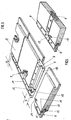
- a substructure indicated in FIGS. 1 and 7 is provided in the form of parallel slats 1 arranged at intervals corresponding to one another, to which the panels 2, as shown in FIG. 1, are fastened by screws 3 etc.
- the adjacent panels are brought circumferentially into tongue and groove engagement with adjacent panels.
- the panels 2 are provided with grooves 4 on two adjoining sides of their circumference and with springs 5 on the remaining two sides of their circumference. The arrangement of the grooves 4 and tongues 5 can be seen clearly from FIGS. 2 and 3.
- one longitudinal side and a transverse side adjoining it at right angles are provided with a groove 4 which is delimited by an upper, that is to say a groove-limiting leg 6 on the visible side and a lower, that is to say a groove-limiting leg 7 on the rear.
- a corresponding, outwardly projecting spring 5 is provided on the opposite longitudinal and transverse sides of the panel 2.
- the panels 2 each consist of one tabular base body 8, which on its springs 5 assigned longitudinal and transverse sides, each with an edge strip 9 is provided, from which the associated spring 5 protrudes outwards.
- the edge strips 9 form practically edge areas that the an inner panel area forming base body 8 on two Include pages.
- the visible surface of the edge strips 9 is, as is best Figure 5 is clearly visible, level with the visible side Surface of the associated spring 5. This is opposite the visible surface of the base body 8 by the thickness of the groove groove limb 6 on the visible side, so that as Figure 2 clearly shows, a step with the height s results.
- the rear surface of the edge strips 9 is, as can be seen from Figure 3 is flush with the back of the body 8. This way there is a continuous back of the panel 2, so that this also in the area of the sidebars Substructure 1 comes to rest, as can be seen from FIG. 1. This enables a reliable screwing of the panels 2 in Area of the marginal ridges 9.
- the groove limiter on the visible side 6, as FIG. 1 further shows, correspondingly wider than that rear groove limiting leg 7.
- the edge strips 9 to cover completely corresponds to the protrusion of the visible side Groove limiting leg 6 over the rear groove limiting leg 7 the distance between the base body 8 and the Neck cross-section of the spring 5 on the associated edge strip 9.
- the edge strips 9 can with their spring distant flank to the facing side surface of the base body 8, where a pin and / or glue connection is provided for connection can be.
- the edge strips 9 are through a tongue and groove connection connected to the base body 8.
- the edge strips 9 have a T-shaped cross section. This contains a middle one, with its underside on the Substructure 1 that can be brought into contact, designated in FIG. 1 Web 11, from which opposing flanges protrude, of which the flange directed away from the base body 8 is at the top already mentioned spring 5 running on the outside of the panel forms, while the base body 8 facing flange forms inner fastening spring 12, which in an associated groove 13th of the base body 8 engages, as can be seen from FIG. 1.
- the Base body 8 is accordingly in the area of all four circumferential sides grooved, being in the area of one long side and one on it then the transverse side of the springs 5 of the neighboring Panels assigned grooves 4 and in the area of the opposite Longitudinal and transverse sides of the springs 12 to be attached there Edge strips 9 associated grooves 13 are provided.
- the grooves 4 and 13 expediently have the same clear width and are equally spaced from the surface of the base body 8, so that the edge strips 9 have the aforementioned T-shape can.
- the flanges of the T-shaped springs 5 and 12, respectively Edge strips 9 have the same width that the depth of the Groove 13 or the groove 4 in the area of the rear groove limiting leg 7 corresponds.
- the supernatant of the visible side Groove limiting leg 6 over the rear groove limiting leg 7 suitably corresponds to the width of the middle Web 11 so that it can be completely covered.
- the spring 12 can by a glue connection in the associated Groove 13 be attached.
- a positive connection provided which is a sizing dispensable.
- the one engaging in the groove 13 Leg 12, as shown in Figures 1 and 4, with one over his Length continuous locking web 14 provided in an assigned Groove 15 of the facing side wall of the groove 13 can be snapped into place.
- the edge strip 9 assigned to a long side projects with its End area over the transverse side of the Base body 8 also.
- the protrusion corresponds to the width of the Web 11 plus the spring 5 of the edge strips projecting therefrom 9, as indicated in Figure 5 at b.
- the face of the Base body 8 overhanging edge strip 9 is accordingly flush with the outer flank 18 of the spring 5 which is transverse to it extending edge strip 9.
- the outward-pointing spring 5 of the Transverse edge strip 9 is coplanar with the after inside pointing spring 12 assigned to the long side Border 9, so that there is a continuous surface.
- the one with the spring 5 of the edge strip 9 assigned to the transverse side overlapping area of the spring 12 of the long side assigned edge bar 9 accordingly forms a Extension of the transverse spring 5 to the web 11 of the Longitudinal strip assigned to the long side 9.
- the basic body 8 facing side flank of the web 11 of the long side assigned edge bar 9 is accordingly on one of the width the spring 5 of the edge strip assigned to the transverse side corresponding width from the projection of the transverse side associated sidebar not covered. This uncovered
- the area is formed by a grid that is also indicated on the right in FIG. second support surface 19.
- the mutual support surfaces 17, 19 are mutually Support intervention, as indicated at 22.
- this support intervention can the newly connected panel 2a in the area of its end no longer in support surface normal Direction of the bandage already attached to the substructure move away, that is one in Figure 7 below by an arrow 23 indicated movement is excluded. It is therefore sufficient that support panel 2 to be connected at the other end, such as is indicated by the support arrow 24, while in one with a Batten 10 of the substructure 1 in congruence a screw is screwed in.
- This Panel 2a supports with one hand according to support arrow 24 and with the other hand operated a screwdriver.
- the base body 8 has accordingly one designed in a desired type of wood, e.g. veneered visible side.
- a desired type of wood e.g. veneered visible side.
- the edge strips 9 can easily and inexpensively as chipboard moldings be formed. But here would also be a solid wood version conceivable. Also training as an existing plastic Extrusion products would be conceivable.
Landscapes
- Engineering & Computer Science (AREA)
- Architecture (AREA)
- Civil Engineering (AREA)
- Structural Engineering (AREA)
- Life Sciences & Earth Sciences (AREA)
- Wood Science & Technology (AREA)
- Finishing Walls (AREA)
- Pharmaceuticals Containing Other Organic And Inorganic Compounds (AREA)
- Panels For Use In Building Construction (AREA)
- Floor Finish (AREA)
Abstract
Description
- Figur 1
- einen Schnitt durch den Randbereich einander benachbarter, aneinander anzuschließender Paneele in auseinandergezogener Darstellung,
- Figur 2
- eine Draufsicht auf die Sichtseite eines erfindungsgemäßen Paneels in perspektivischer Darstellung,
- Figur 3
- eine Draufsicht auf die Rückseite eines erfindungsgemäßen Paneels in perspektivischer Darstellung,
- Figur 4
- eine Ansicht einer separaten Randleiste,
- Figur 5
- eine Draufsicht auf die Rückseite von zwei mit ihren Stützflächen in Eingriff bringbaren Paneelen in auseinandergezogener Darstellung,
- Figur 6
- die Paneele gemäß Figur 5 in zusammengeschobenem Zustand und
- Figur 7
- ein Montagebeispiel mit drei aufeinanderfolgenden Arbeitsgängen.
Die Anordnung der Nuten 4 und Federn 5 ist anschaulich aus den Figuren 2 und 3 entnehmbar. Jeweils eine Längsseite und eine rechtwinklig hieran anschließende Querseite ist mit einer Nut 4 versehen, die durch einen oberen, das heißt sichtseitigen Nutbegrenzungsschenkel 6 und einen unteren, das heißt rückseitigen Nutbegrenzungsschenkel 7 begrenzt wird. An den jeweils gegenüberliegenden Längs- und Querseiten des Paneels 2 ist jeweils eine entsprechende, nach außen auskragende Feder 5 vorgesehen.
Claims (10)
- Paneel, insbesondere für Wand- und/oder Deckenverkleidungen, das mit benachbarten Paneelen (2) in Nut- und Federeingriff bringbar ist und an einer Längsseite und einer Querseite jeweils eine durch einen sichtseitigen und einen rückseitigen Nutbegrenzungsschenkel (6 bzw. 7) begrenzte Nut (4) und an den jeweils gegenüberliegenden Längs- und Querseiten jeweils eine entsprechende Feder (5) aufweist, dadurch gekennzeichnet, dass die Federn (5) von einem benachbarten, leistenförmigen Randbereich des Paneels (2) abstehen, der gegenüber der sichtseitigen Oberfläche eines innerhalb des Randbereichs liegenden, inneren Paneelbereichs in Form einer Stufe abgesenkt ist und der rückseitig bündig mit dem inneren Paneelbereich ist und der mit wenigstens einer Bohrungsreihe mit mehren, über seine Länge verteilten Durchgangsbohrungen (10 verseheh ist.
- Paneel nach Anspruch 1, dadurch gekennzeichnet, dass der leistenförmige Randbereich gegenüber der sichtseitigen Oberfläche des inneren Paneelbereichs um die Dicke des sichtseitigen Nutbegrenzungsschenkels (6) abgesenkt ist.
- Paneel nach einem der vorhergehenden Ansprüche, dadurch gekennzeichnet, dass der sichtseitige Nutbegrenzungsschenkel (6) den gegenüberliegenden Nutbegrenzungsschenkel (7) um die Breite des abgesenkten Randbereichs überragt.
- Paneel nach einem der vorhergehenden Ansprüche, dadurch gekennzeichnet, dass die abgesenkten Randbereiche durch eine an die jeweils zugeordnete Seite eines den inneren Paneelbereich bildenden Grundkörpers (8) angesetzte Randleisten (9) gebildet wird.
- Paneel nach Anspruch 4, dadurch gekennzeichnet, dass die Randleisten (9) einen T-förmigen Querschnitt aufweisen und mit dem Grundkörper (8) in Nut- und Federeingriff sind.
- Paneel nach Anspruch 5, dadurch gekennzeichnet, dass der in eine zugeordnete Nut (13) des Grundkörpers (8) eingreifende Flansch (12) der T-förmigen Randleiste (9) mit einem durchgehenden Raststeg (14) versehen ist, der in eine im Bereich einer Seitenwand der zugeordneten Nut (13) des Grundkörpers (8) vorgesehene Rille (15) einrastbar ist.
- Paneel nach einem der vorhergehenden Ansprüche, dadurch gekennzeichnet, dass die vorzugsweise durch Randleisten (9) gebildeten, leistenförmigen Randbereiche des Paneels (2) mit ihren voneinander entfernten Enden am Nutgrund der quer hierzu verlaufenden Nuten (4) des Paneels beginnen und mit ihren einander zugewandten Enden mit stumpfem Stoß aneinander anschließen, wobei der eine Randbereich die Stirnseite des anderen Randbereich überdeckt.
- Paneel nach Anspruch 7, dadurch gekennzeichnet, dass die einer Längsseite des Paneels zugeordnete Randleiste (9) die Stirnseite der der hieran anschließenden Querseite zugeordneten Randleiste (9) überdeckt.
- Paneel nach einem der vorhergehenden Ansprüche 4 bis 8, dadurch gekennzeichnet, dass der Grundkörper (8) aus Massivholz besteht und/oder zumindest sichtseitig furniert ist.
- Paneel nach einem der vorhergehenden Ansprüche 4 bis 9, dadurch gekennzeichnet, dass die Randleisten (9) als Pressspanformlinge ausgebildet sind.
Applications Claiming Priority (2)
| Application Number | Priority Date | Filing Date | Title |
|---|---|---|---|
| DE10239146A DE10239146B4 (de) | 2002-08-27 | 2002-08-27 | Paneel |
| DE10239146 | 2002-08-27 |
Publications (2)
| Publication Number | Publication Date |
|---|---|
| EP1394337A1 true EP1394337A1 (de) | 2004-03-03 |
| EP1394337B1 EP1394337B1 (de) | 2006-03-22 |
Family
ID=31197397
Family Applications (1)
| Application Number | Title | Priority Date | Filing Date |
|---|---|---|---|
| EP03019227A Expired - Lifetime EP1394337B1 (de) | 2002-08-27 | 2003-08-26 | Paneel |
Country Status (3)
| Country | Link |
|---|---|
| EP (1) | EP1394337B1 (de) |
| AT (1) | ATE321176T1 (de) |
| DE (2) | DE10239146B4 (de) |
Cited By (6)
| Publication number | Priority date | Publication date | Assignee | Title |
|---|---|---|---|---|
| FR2880047A1 (fr) * | 2004-12-24 | 2006-06-30 | Tecnopan Sa | Panneau de plancher demontable |
| DE202009017071U1 (de) | 2009-12-17 | 2010-03-18 | Firstwood Gmbh | Profilbrettverkleidung |
| FR2993590A1 (fr) * | 2012-07-17 | 2014-01-24 | Sigebene | Procede et dispositif pour la fixation bord a bord de panneaux rigides sur une paroi ou un mur |
| EP2664728A3 (de) * | 2012-05-14 | 2017-07-12 | Matclad Limited | Fliesenkit und Verfahren |
| CN107130760A (zh) * | 2017-06-22 | 2017-09-05 | 嘉兴天美环保集成墙面有限公司 | 一种便于安装的组合墙板 |
| EP3483354A1 (de) * | 2017-11-09 | 2019-05-15 | Hilmar Grünberger | Fassadenverkleidung zum verkleiden einer wand oder gebäudefassade |
Families Citing this family (3)
| Publication number | Priority date | Publication date | Assignee | Title |
|---|---|---|---|---|
| DE102011001843A1 (de) | 2011-04-06 | 2012-10-11 | Guido Schulte | Flächenverkleidung von Wand- oder Deckenbereichen sowie Verfahren zur Verkleidung von Wand- oder Deckenbereich |
| AT13835U1 (de) | 2013-08-12 | 2014-09-15 | Sihga Handels Gmbh | Befestigung von Bohlen an einer Unterkonstruktion |
| FR3011256B1 (fr) * | 2013-09-27 | 2016-03-18 | Loisirs Equipements Soc | Panneau de revetement de surface, ensemble comprenant au moins deux panneaux du type precite et revetement de surface obtenu |
Citations (7)
| Publication number | Priority date | Publication date | Assignee | Title |
|---|---|---|---|---|
| FR1569989A (de) * | 1968-04-23 | 1969-06-06 | ||
| DE7635021U1 (de) * | 1976-11-05 | 1978-02-02 | Mero-Werke Kg Dr.-Ing. Max Mengeringhausen, 8700 Wuerzburg | Bauteilesatz fuer einen montagefussboden |
| DE3619046A1 (de) * | 1986-06-06 | 1987-12-10 | Gyproc Gmbh | Gipsbauplatte und aus solchen bauplatten hergestellte druckverteilungsplatte |
| FR2645219A1 (fr) * | 1988-12-30 | 1990-10-05 | Tuduri Gerard | Systeme d'assemblage de panneaux |
| CA2305852A1 (en) * | 2000-04-14 | 2001-10-14 | Harry W. Eberle, Iii | Anchoring biscuit device |
| DE10044017C1 (de) * | 2000-09-06 | 2002-04-18 | Kronotec Ag | Einrichtung zum Verbinden von Bodenpaneelen |
| US6421970B1 (en) * | 1995-03-07 | 2002-07-23 | Perstorp Flooring Ab | Flooring panel or wall panel and use thereof |
Family Cites Families (2)
| Publication number | Priority date | Publication date | Assignee | Title |
|---|---|---|---|---|
| DE2447046A1 (de) * | 1974-10-02 | 1976-04-15 | Hilko Juerrens | Paneelplatte zur wand- und deckenverkleidung |
| DE7600832U1 (de) * | 1976-01-14 | 1976-05-06 | Gebr. Thome Kg, 7501 Forchheim | Bauelementesatz zur erstellung von fabrikmaessig vorgefertigten wandvertaeferungen |
-
2002
- 2002-08-27 DE DE10239146A patent/DE10239146B4/de not_active Expired - Fee Related
-
2003
- 2003-08-26 DE DE50302718T patent/DE50302718D1/de not_active Expired - Lifetime
- 2003-08-26 AT AT03019227T patent/ATE321176T1/de active
- 2003-08-26 EP EP03019227A patent/EP1394337B1/de not_active Expired - Lifetime
Patent Citations (7)
| Publication number | Priority date | Publication date | Assignee | Title |
|---|---|---|---|---|
| FR1569989A (de) * | 1968-04-23 | 1969-06-06 | ||
| DE7635021U1 (de) * | 1976-11-05 | 1978-02-02 | Mero-Werke Kg Dr.-Ing. Max Mengeringhausen, 8700 Wuerzburg | Bauteilesatz fuer einen montagefussboden |
| DE3619046A1 (de) * | 1986-06-06 | 1987-12-10 | Gyproc Gmbh | Gipsbauplatte und aus solchen bauplatten hergestellte druckverteilungsplatte |
| FR2645219A1 (fr) * | 1988-12-30 | 1990-10-05 | Tuduri Gerard | Systeme d'assemblage de panneaux |
| US6421970B1 (en) * | 1995-03-07 | 2002-07-23 | Perstorp Flooring Ab | Flooring panel or wall panel and use thereof |
| CA2305852A1 (en) * | 2000-04-14 | 2001-10-14 | Harry W. Eberle, Iii | Anchoring biscuit device |
| DE10044017C1 (de) * | 2000-09-06 | 2002-04-18 | Kronotec Ag | Einrichtung zum Verbinden von Bodenpaneelen |
Cited By (8)
| Publication number | Priority date | Publication date | Assignee | Title |
|---|---|---|---|---|
| FR2880047A1 (fr) * | 2004-12-24 | 2006-06-30 | Tecnopan Sa | Panneau de plancher demontable |
| DE202009017071U1 (de) | 2009-12-17 | 2010-03-18 | Firstwood Gmbh | Profilbrettverkleidung |
| EP2336451A2 (de) | 2009-12-17 | 2011-06-22 | Firstwood GmbH | Profilbrettverkleidung |
| EP2664728A3 (de) * | 2012-05-14 | 2017-07-12 | Matclad Limited | Fliesenkit und Verfahren |
| FR2993590A1 (fr) * | 2012-07-17 | 2014-01-24 | Sigebene | Procede et dispositif pour la fixation bord a bord de panneaux rigides sur une paroi ou un mur |
| CN107130760A (zh) * | 2017-06-22 | 2017-09-05 | 嘉兴天美环保集成墙面有限公司 | 一种便于安装的组合墙板 |
| CN107130760B (zh) * | 2017-06-22 | 2023-06-09 | 嘉兴天美环保集成墙面有限公司 | 一种便于安装的组合墙板 |
| EP3483354A1 (de) * | 2017-11-09 | 2019-05-15 | Hilmar Grünberger | Fassadenverkleidung zum verkleiden einer wand oder gebäudefassade |
Also Published As
| Publication number | Publication date |
|---|---|
| DE10239146A1 (de) | 2004-03-25 |
| DE10239146B4 (de) | 2008-03-27 |
| DE50302718D1 (de) | 2006-05-11 |
| ATE321176T1 (de) | 2006-04-15 |
| EP1394337B1 (de) | 2006-03-22 |
Similar Documents
| Publication | Publication Date | Title |
|---|---|---|
| DE4215273C2 (de) | Belag zur Verkleidung von Boden-, Wand- und/oder Deckenflächen, insbesondere in der Art eines Riemenfußbodens | |
| EP2208835B1 (de) | Paneel, insbesondere Fussbodenpaneel | |
| DE69302144T2 (de) | Verbundprofilanordnung wie Rinne oder dergleichen | |
| DE19516530A1 (de) | Dichtungsvorrichtung, insbesondere für Türflügel | |
| DE102009038750A1 (de) | Fußboden, erstellt aus Fußbodenpaneelen mit separaten Verbindungsmitteln | |
| DE102013106251A1 (de) | Montagesystem für einen Bodenbelag | |
| EP1394337A1 (de) | Paneel | |
| EP0802287A2 (de) | Höhenverstellbarer Drainagerost | |
| EP2357299A2 (de) | Fußbodenpaneel | |
| EP2320006B1 (de) | Fußbodenpaneel mit Klettverschluss-Elementen | |
| AT1025U1 (de) | Bauelement sowie damit hergestellte wandverkleidung | |
| EP2105065A1 (de) | Möbelkorpus | |
| DE9205273U1 (de) | Befestigungselement zur verdeckten Halterung | |
| DE202022105475U1 (de) | Bodenanordnung, längliches Bodenprofil und Abschlussprofil | |
| EP3296486B1 (de) | Gebäudeverkleidung mit einem beschlagverbund für das verbinden von länglichen deckelementen | |
| DE3729378C2 (de) | ||
| DE202014004005U1 (de) | Beschlagteil und Paneel zur Verwendung mit einem solchen | |
| DE20013238U1 (de) | Blechanordnung | |
| DE202010007198U1 (de) | Dielenverlegesystem | |
| AT358258B (de) | Befestigungselement | |
| DE3016011C2 (de) | ||
| DE1658983C3 (de) | Abdichtung für Dehnungsfugen | |
| DE202021100644U1 (de) | Bodenprofile für Balkone aus Aluminium | |
| DE9115330U1 (de) | Kupplung für Profile für abgehängte Decken und dazu angewandte Profile | |
| AT258537B (de) | Aufgehängte Unterdecke |
Legal Events
| Date | Code | Title | Description |
|---|---|---|---|
| PUAI | Public reference made under article 153(3) epc to a published international application that has entered the european phase |
Free format text: ORIGINAL CODE: 0009012 |
|
| AK | Designated contracting states |
Kind code of ref document: A1 Designated state(s): AT BE BG CH CY CZ DE DK EE ES FI FR GB GR HU IE IT LI LU MC NL PT RO SE SI SK TR |
|
| AX | Request for extension of the european patent |
Extension state: AL LT LV MK |
|
| 17P | Request for examination filed |
Effective date: 20040824 |
|
| AKX | Designation fees paid |
Designated state(s): AT BE BG CH CY CZ DE DK EE ES FI FR GB GR HU IE IT LI LU MC NL PT RO SE SI SK TR |
|
| 17Q | First examination report despatched |
Effective date: 20050124 |
|
| GRAP | Despatch of communication of intention to grant a patent |
Free format text: ORIGINAL CODE: EPIDOSNIGR1 |
|
| GRAS | Grant fee paid |
Free format text: ORIGINAL CODE: EPIDOSNIGR3 |
|
| GRAA | (expected) grant |
Free format text: ORIGINAL CODE: 0009210 |
|
| AK | Designated contracting states |
Kind code of ref document: B1 Designated state(s): AT BE BG CH CY CZ DE DK EE ES FI FR GB GR HU IE IT LI LU MC NL PT RO SE SI SK TR |
|
| PG25 | Lapsed in a contracting state [announced via postgrant information from national office to epo] |
Ref country code: RO Free format text: LAPSE BECAUSE OF FAILURE TO SUBMIT A TRANSLATION OF THE DESCRIPTION OR TO PAY THE FEE WITHIN THE PRESCRIBED TIME-LIMIT Effective date: 20060322 Ref country code: NL Free format text: LAPSE BECAUSE OF FAILURE TO SUBMIT A TRANSLATION OF THE DESCRIPTION OR TO PAY THE FEE WITHIN THE PRESCRIBED TIME-LIMIT Effective date: 20060322 Ref country code: GB Free format text: LAPSE BECAUSE OF FAILURE TO SUBMIT A TRANSLATION OF THE DESCRIPTION OR TO PAY THE FEE WITHIN THE PRESCRIBED TIME-LIMIT Effective date: 20060322 Ref country code: SI Free format text: LAPSE BECAUSE OF FAILURE TO SUBMIT A TRANSLATION OF THE DESCRIPTION OR TO PAY THE FEE WITHIN THE PRESCRIBED TIME-LIMIT Effective date: 20060322 Ref country code: SK Free format text: LAPSE BECAUSE OF FAILURE TO SUBMIT A TRANSLATION OF THE DESCRIPTION OR TO PAY THE FEE WITHIN THE PRESCRIBED TIME-LIMIT Effective date: 20060322 Ref country code: IE Free format text: LAPSE BECAUSE OF FAILURE TO SUBMIT A TRANSLATION OF THE DESCRIPTION OR TO PAY THE FEE WITHIN THE PRESCRIBED TIME-LIMIT Effective date: 20060322 |
|
| REG | Reference to a national code |
Ref country code: GB Ref legal event code: FG4D Free format text: NOT ENGLISH |
|
| REG | Reference to a national code |
Ref country code: CH Ref legal event code: EP |
|
| REG | Reference to a national code |
Ref country code: IE Ref legal event code: FG4D Free format text: LANGUAGE OF EP DOCUMENT: GERMAN |
|
| REF | Corresponds to: |
Ref document number: 50302718 Country of ref document: DE Date of ref document: 20060511 Kind code of ref document: P |
|
| PG25 | Lapsed in a contracting state [announced via postgrant information from national office to epo] |
Ref country code: SE Free format text: LAPSE BECAUSE OF FAILURE TO SUBMIT A TRANSLATION OF THE DESCRIPTION OR TO PAY THE FEE WITHIN THE PRESCRIBED TIME-LIMIT Effective date: 20060622 Ref country code: DK Free format text: LAPSE BECAUSE OF FAILURE TO SUBMIT A TRANSLATION OF THE DESCRIPTION OR TO PAY THE FEE WITHIN THE PRESCRIBED TIME-LIMIT Effective date: 20060622 Ref country code: BG Free format text: LAPSE BECAUSE OF FAILURE TO SUBMIT A TRANSLATION OF THE DESCRIPTION OR TO PAY THE FEE WITHIN THE PRESCRIBED TIME-LIMIT Effective date: 20060622 |
|
| PG25 | Lapsed in a contracting state [announced via postgrant information from national office to epo] |
Ref country code: ES Free format text: LAPSE BECAUSE OF FAILURE TO SUBMIT A TRANSLATION OF THE DESCRIPTION OR TO PAY THE FEE WITHIN THE PRESCRIBED TIME-LIMIT Effective date: 20060703 |
|
| PG25 | Lapsed in a contracting state [announced via postgrant information from national office to epo] |
Ref country code: PT Free format text: LAPSE BECAUSE OF FAILURE TO SUBMIT A TRANSLATION OF THE DESCRIPTION OR TO PAY THE FEE WITHIN THE PRESCRIBED TIME-LIMIT Effective date: 20060822 |
|
| PG25 | Lapsed in a contracting state [announced via postgrant information from national office to epo] |
Ref country code: MC Free format text: LAPSE BECAUSE OF NON-PAYMENT OF DUE FEES Effective date: 20060831 |
|
| NLV1 | Nl: lapsed or annulled due to failure to fulfill the requirements of art. 29p and 29m of the patents act | ||
| GBV | Gb: ep patent (uk) treated as always having been void in accordance with gb section 77(7)/1977 [no translation filed] |
Effective date: 20060322 |
|
| REG | Reference to a national code |
Ref country code: IE Ref legal event code: FD4D |
|
| PLBE | No opposition filed within time limit |
Free format text: ORIGINAL CODE: 0009261 |
|
| STAA | Information on the status of an ep patent application or granted ep patent |
Free format text: STATUS: NO OPPOSITION FILED WITHIN TIME LIMIT |
|
| 26N | No opposition filed |
Effective date: 20061227 |
|
| EN | Fr: translation not filed | ||
| PG25 | Lapsed in a contracting state [announced via postgrant information from national office to epo] |
Ref country code: GR Free format text: LAPSE BECAUSE OF FAILURE TO SUBMIT A TRANSLATION OF THE DESCRIPTION OR TO PAY THE FEE WITHIN THE PRESCRIBED TIME-LIMIT Effective date: 20060623 Ref country code: FR Free format text: LAPSE BECAUSE OF FAILURE TO SUBMIT A TRANSLATION OF THE DESCRIPTION OR TO PAY THE FEE WITHIN THE PRESCRIBED TIME-LIMIT Effective date: 20070309 |
|
| PG25 | Lapsed in a contracting state [announced via postgrant information from national office to epo] |
Ref country code: FI Free format text: LAPSE BECAUSE OF FAILURE TO SUBMIT A TRANSLATION OF THE DESCRIPTION OR TO PAY THE FEE WITHIN THE PRESCRIBED TIME-LIMIT Effective date: 20060322 Ref country code: EE Free format text: LAPSE BECAUSE OF FAILURE TO SUBMIT A TRANSLATION OF THE DESCRIPTION OR TO PAY THE FEE WITHIN THE PRESCRIBED TIME-LIMIT Effective date: 20060322 |
|
| PG25 | Lapsed in a contracting state [announced via postgrant information from national office to epo] |
Ref country code: TR Free format text: LAPSE BECAUSE OF FAILURE TO SUBMIT A TRANSLATION OF THE DESCRIPTION OR TO PAY THE FEE WITHIN THE PRESCRIBED TIME-LIMIT Effective date: 20060322 Ref country code: HU Free format text: LAPSE BECAUSE OF FAILURE TO SUBMIT A TRANSLATION OF THE DESCRIPTION OR TO PAY THE FEE WITHIN THE PRESCRIBED TIME-LIMIT Effective date: 20060923 Ref country code: LU Free format text: LAPSE BECAUSE OF NON-PAYMENT OF DUE FEES Effective date: 20060826 |
|
| PG25 | Lapsed in a contracting state [announced via postgrant information from national office to epo] |
Ref country code: FR Free format text: LAPSE BECAUSE OF FAILURE TO SUBMIT A TRANSLATION OF THE DESCRIPTION OR TO PAY THE FEE WITHIN THE PRESCRIBED TIME-LIMIT Effective date: 20060322 Ref country code: CY Free format text: LAPSE BECAUSE OF FAILURE TO SUBMIT A TRANSLATION OF THE DESCRIPTION OR TO PAY THE FEE WITHIN THE PRESCRIBED TIME-LIMIT Effective date: 20060322 |
|
| PGFP | Annual fee paid to national office [announced via postgrant information from national office to epo] |
Ref country code: CZ Payment date: 20080811 Year of fee payment: 6 |
|
| PG25 | Lapsed in a contracting state [announced via postgrant information from national office to epo] |
Ref country code: IT Free format text: LAPSE BECAUSE OF NON-PAYMENT OF DUE FEES Effective date: 20070826 |
|
| PG25 | Lapsed in a contracting state [announced via postgrant information from national office to epo] |
Ref country code: CZ Free format text: LAPSE BECAUSE OF NON-PAYMENT OF DUE FEES Effective date: 20090826 |
|
| PGFP | Annual fee paid to national office [announced via postgrant information from national office to epo] |
Ref country code: IT Payment date: 20070828 Year of fee payment: 5 |
|
| PGRI | Patent reinstated in contracting state [announced from national office to epo] |
Ref country code: IT Effective date: 20110616 |
|
| PGFP | Annual fee paid to national office [announced via postgrant information from national office to epo] |
Ref country code: BE Payment date: 20110822 Year of fee payment: 9 |
|
| BERE | Be: lapsed |
Owner name: *FENDT HERMANN Effective date: 20120831 |
|
| PG25 | Lapsed in a contracting state [announced via postgrant information from national office to epo] |
Ref country code: BE Free format text: LAPSE BECAUSE OF NON-PAYMENT OF DUE FEES Effective date: 20120831 |
|
| PGFP | Annual fee paid to national office [announced via postgrant information from national office to epo] |
Ref country code: CH Payment date: 20130826 Year of fee payment: 11 Ref country code: AT Payment date: 20130821 Year of fee payment: 11 |
|
| PGRI | Patent reinstated in contracting state [announced from national office to epo] |
Ref country code: IT Effective date: 20110616 |
|
| REG | Reference to a national code |
Ref country code: CH Ref legal event code: PL |
|
| REG | Reference to a national code |
Ref country code: AT Ref legal event code: MM01 Ref document number: 321176 Country of ref document: AT Kind code of ref document: T Effective date: 20140826 |
|
| PG25 | Lapsed in a contracting state [announced via postgrant information from national office to epo] |
Ref country code: LI Free format text: LAPSE BECAUSE OF NON-PAYMENT OF DUE FEES Effective date: 20140831 Ref country code: CH Free format text: LAPSE BECAUSE OF NON-PAYMENT OF DUE FEES Effective date: 20140831 |
|
| PG25 | Lapsed in a contracting state [announced via postgrant information from national office to epo] |
Ref country code: AT Free format text: LAPSE BECAUSE OF NON-PAYMENT OF DUE FEES Effective date: 20140826 |
|
| PGFP | Annual fee paid to national office [announced via postgrant information from national office to epo] |
Ref country code: DE Payment date: 20150831 Year of fee payment: 13 |
|
| REG | Reference to a national code |
Ref country code: DE Ref legal event code: R119 Ref document number: 50302718 Country of ref document: DE |
|
| PG25 | Lapsed in a contracting state [announced via postgrant information from national office to epo] |
Ref country code: DE Free format text: LAPSE BECAUSE OF NON-PAYMENT OF DUE FEES Effective date: 20170301 |