EP1394371A2 - Pompe de graissage placée dans le carter à huile - Google Patents
Pompe de graissage placée dans le carter à huile Download PDFInfo
- Publication number
- EP1394371A2 EP1394371A2 EP03019301A EP03019301A EP1394371A2 EP 1394371 A2 EP1394371 A2 EP 1394371A2 EP 03019301 A EP03019301 A EP 03019301A EP 03019301 A EP03019301 A EP 03019301A EP 1394371 A2 EP1394371 A2 EP 1394371A2
- Authority
- EP
- European Patent Office
- Prior art keywords
- oil
- side chamber
- internal combustion
- combustion engine
- lubricating
- Prior art date
- Legal status (The legal status is an assumption and is not a legal conclusion. Google has not performed a legal analysis and makes no representation as to the accuracy of the status listed.)
- Granted
Links
Images


Classifications
-
- F—MECHANICAL ENGINEERING; LIGHTING; HEATING; WEAPONS; BLASTING
- F01—MACHINES OR ENGINES IN GENERAL; ENGINE PLANTS IN GENERAL; STEAM ENGINES
- F01M—LUBRICATING OF MACHINES OR ENGINES IN GENERAL; LUBRICATING INTERNAL COMBUSTION ENGINES; CRANKCASE VENTILATING
- F01M1/00—Pressure lubrication
- F01M1/02—Pressure lubrication using lubricating pumps
-
- F—MECHANICAL ENGINEERING; LIGHTING; HEATING; WEAPONS; BLASTING
- F01—MACHINES OR ENGINES IN GENERAL; ENGINE PLANTS IN GENERAL; STEAM ENGINES
- F01M—LUBRICATING OF MACHINES OR ENGINES IN GENERAL; LUBRICATING INTERNAL COMBUSTION ENGINES; CRANKCASE VENTILATING
- F01M11/00—Component parts, details or accessories, not provided for in, or of interest apart from, groups F01M1/00 - F01M9/00
- F01M11/0004—Oilsumps
- F01M2011/0037—Oilsumps with different oil compartments
-
- F—MECHANICAL ENGINEERING; LIGHTING; HEATING; WEAPONS; BLASTING
- F01—MACHINES OR ENGINES IN GENERAL; ENGINE PLANTS IN GENERAL; STEAM ENGINES
- F01M—LUBRICATING OF MACHINES OR ENGINES IN GENERAL; LUBRICATING INTERNAL COMBUSTION ENGINES; CRANKCASE VENTILATING
- F01M11/00—Component parts, details or accessories, not provided for in, or of interest apart from, groups F01M1/00 - F01M9/00
- F01M11/0004—Oilsumps
- F01M2011/0079—Oilsumps with the oil pump integrated or fixed to sump
Definitions
- the present invention relates to a snowmobile comprising a body supporting a drive means and an internal combustion engine which is coupled with the drive means and comprises a crankcase, an oil pan having two side chambers for storing lubricating oil in the inside thereof, and at least one oil pump.
- the snowmobile includes: drive means which is supported in a body thereof and mounted to travel on a traveling surface makes it possible to drive the body to travel with a rotational movement thereof; and an internal combustion engine for travel drive which is supported in the body and is interlockingly coupled with the drive means.
- this drive means drives to travel the snowmobile, whereby the snowmobile is made capable of traveling on a traveling surface.
- the oil pump is driven following the driving of the internal combustion engine and the lubricating oil stored inside the oil pan is drawn out, and this lubricating oil is supplied to respective lubricated parts of the internal combustion engine and lubricates these parts and, then, is returned to the inside of the oil pan to be drawn out from the inside of the oil pan again by the oil pump as described above. Then, smooth driving of this internal combustion engine is continued by lubrication of the respective lubricated parts of the internal combustion engine.
- a simple oil pump is housed only in the one side chamber of the one side chamber and the other side chamber to interlockingly couple this oil pump to the crank shaft by the interlocking means, thereby making the structure of the lubricating device more simple.
- the oil pump tends to draw out lubricating oil only from the one side chamber, in which this oil pump is housed, and lubricating oil from the other side chamber becomes insufficient. Consequently, it becomes likely that smooth supply of the lubricating oil to the respective lubricated parts in the internal combustion engine is hindered thereafter.
- the present invention has been devised in view of the circumstances as described above, and therefore it is an object of the invention to improve a snowmobile of the above kind in that a structure of a lubricating device of an internal combustion engine in a snowmobile is simplified while supply of lubricating oil to respective lubricated parts of the internal combustion engine by this lubricating device is performed smoothly.
- this objective is solved in an inventive manner in that the oil pump is accommodated in a first one of the side chambers.
- the at least one oil pump is housed only in the one side chamber.
- inlet ports for drawing the lubricating oil into the oil pump are opened in the one side chamber and the other side chamber, respectively.
- both of these oil pumps are housed only in the one side chamber such to be arranged compactly.
- an interlocking means can be commonly used for the respective oil pumps, and this interlocking means can be formed with a simple structure, that is, the lubricating device can be formed with a simple structure.
- the inlet ports for the lubricating oil into the oil pumps are opened in the one side chamber and the other side chamber, respectively, even if the oil pumps are housed only in the one side chamber, the lubricating oil can be drawn out from both the one side chamber and the other side chamber by these oil pumps. Thus, the supply of the lubricating oil to respective lubricated parts of the internal combustion engine by the lubricating device is performed smoothly thereafter.
- the oil pumps are provided for the one side chamber and the other side chamber, respectively, the lubricating oil in the one side chamber and the other side chamber is surely drawn out by the oil pumps, respectively.
- the supply of the lubricating oil to respective lubricated parts of the internal combustion engine by the lubricating device is performed more smoothly thereafter.
- the oil pumps are protrudingly provided downward from the lower surface of the crankcase.
- both the oil pumps are housed only in the one side chamber, the pump shafts of these oil pumps are formed integrally with each other, and the pump shafts are interlockingly coupled to the crank shaft via the interlocking means.
- the lubricating device can be formed with a simpler structure.
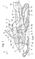
- reference numeral 1 denotes a saddle-ride type vehicle, and a snowmobile is shown as an example of the same.
- arrow Fr in the figure indicates the front of this snowmobile 1.
- the snowmobile 1 includes: drive means 4 which is supported at the rear part of a body 2 and mounted on a traveling surface 3, which is a snow surface, and makes it possible to travel the body 2 with a rotational movement thereof; a pair of left and right steering skis 5, 5 which are born by the front part of the body 2 so as to be steered freely and mounted on the traveling surface 3 and makes it possible to steer the body 2 with steering thereof; an internal combustion engine 6 for travel drive which is arranged inside a middle part in a longitudinal direction of the body 2 and supported in this middle part; an automatic speed-change type transmission 7 which is interlockingly coupled to this internal combustion engine 6; and a gear type power transmission device 8 which is interlockingly coupled to this transmission 7 and, on the other hand, interlockingly couples the drive means 4. That is, the drive means 4 and the internal combustion engine 6 are interlockingly coupled with each other via the transmission 7 and the power transmission device 8, and a steering wheel 9 interlockingly coupled with the respective steering skis 5 is born in the body 2.
- the body 2 includes a body main body 13 which has a body frame to be a framework thereof; a seat 14 which is born in the body main body 13 in the rear of the steering wheel 9 and makes it possible for a rider to sit thereon; foot rests 15 which are protrudingly provided in left and right sides of the body main body 13 and make it possible for the rider, who sits on the seat 14, to place feet thereon; a shield 16 which is protrudingly provided so as to extend upward from the body main body 13 in the vicinity of the front of the steering wheel 9.
- the drive means 4 includes drive and driven rotation wheels 18, 19 rotatably born in the body 2 via a suspension system; and a track belt 20 wound around these both rotation wheels 18, 19, and a lower surface in the rear part of this track belt 20 extends substantially horizontally to be in surface contact with the traveling surface 3.
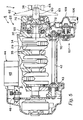
- the internal combustion engine 6 is a four cycle multi-cylinder (three cylinder) engine and includes: an internal combustion engine main body 22 supported in the body 2; an intake system 25 which introduces an air 23 on the atmosphere side and a fuel 24 into this internal combustion engine main body 22; and an exhaust system 27 which discharges an exhaust gas 26 after being burnt in the internal combustion engine main body 22 to the atmosphere side.
- the internal combustion engine main body 22 includes: a crankcase 30 which is supported in the body 2 and bears the crank shaft 29; a cylinder 31 which projects rear upward from this crankcase 30; an oil pan 32 which is provided so as to cover a lower surface side of the crankcase 30 from the underside thereof; a piston 34 slidably fitted in a cylinder hole 33 of the cylinder 31; and a connecting rod 35 which interlockingly couples the crank shaft 29 and the piston 34 with each other, and an axis 36 of the crank shaft 29 extends horizontally in a width direction (lateral direction) of the body 2.
- the internal combustion engine 6 includes: inlet and exhaust passages 37, 38 which are formed in a projected end of the cylinder 31 and cause the inside and the outside of the cylinder hole 33 to communicate with each other; inlet and exhaust valves 39, 40 which close these inlet and exhaust passages 37, 38, respectively, so as to open and close freely; a not-shown valve mechanism which operates the inlet and exhaust valves 39, 40 to open and close appropriately in association with the crank shaft 29; and a spark plug 41 whose discharge section faces a combustion chamber at an upper end of the cylinder hole 33.
- the internal combustion engine 6 includes: a balancer shaft 42 which is arranged in the vicinity above the crank shaft 29 and extends in parallel with this crank shaft 29; gear type interlocking means 43 which interlockingly couples this balancer shaft 42 to the crank shaft 29; and a starter 44 which interlockingly couples the crank shaft 29 to make it possible to start the internal combustion engine 6, and this starter 44 includes a starting motor 45 which is supported in the cylinder 31; and gear type interlocking means 46 which interlockingly couples the crank shaft 29 to this starting motor 45.
- the intake system 25 includes a carburetor 49 which is continuously provided on the front surface side of the cylinder 31 and makes it possible to supply the fuel 24 to the cylinder hole 33 together with the air 23 through the inlet passage 37; and an air cleaner 50 which filters the air 23 on the atmosphere side and supplies it to the carburetor 49, and this air cleaner 50 is arranged above the front surface of the cylinder 31, in front of the upper front surface of this cylinder 31, and in front of and above the balancer shaft 42.
- a carburetor 49 which is continuously provided on the front surface side of the cylinder 31 and makes it possible to supply the fuel 24 to the cylinder hole 33 together with the air 23 through the inlet passage 37
- an air cleaner 50 which filters the air 23 on the atmosphere side and supplies it to the carburetor 49, and this air cleaner 50 is arranged above the front surface of the cylinder 31, in front of the upper front surface of this cylinder 31, and in front of and above the balancer shaft 42.
- the exhaust system 27 includes an exhaust pipe 53 extending backward from the cylinder 31 of the internal combustion engine 6; and a muffler 54 which is coupled to an extended end of this exhaust pipe 53.
- This exhaust pipe 53 includes: a plurality of (three) exhaust pipe members 55 which constitute the front part of this exhaust pipe 53 and extend backward from respective cylinders of the internal combustion engine 6, respectively; a single manifold 56 which constitutes the middle part in the longitudinal direction of the exhaust pipe 53 and causes extended ends of the respective exhaust pipe members 55 to collect each other; and a plurality of (two) other exhaust pipe members 57, 57 which constitute the rear part of the exhaust pipe 53 and cause the muffler 54 to communicate with the manifold 56.
- the transmission 7 includes an input shaft 60 which is arranged on the outside of one end serving as a free end of the crank shaft 29 and on the same axis 36 as this crank shaft 29 and is interlockingly coupled to this crank shaft 29; an output shaft 61 which interlockingly couples the drive means 4 via the power transmission device 8 to output a driving force to this drive means 4; and belt-wound type interlocking means 62 which interlocks the output shaft 61 with the input shaft 60.
- This interlocking means 62 includes a drive pulley 63 which is supported on the input shaft 60 and rotates with this input shaft 60; an idler pulley 64 which is supported on the output shaft 61 and rotates with this output shaft 61; and a V belt 65 which is wound around the drive pulley 63 and the idler pulley 64, and a reduction gear ratio automatically decreases as the input shaft 60 rotates at higher speed.
- the input shaft 60 is interlockingly coupled to the crank shaft 29 as described below. That is, the input shaft 60 is cantilever-supported in the crankcase 30 by a pair of left and right bearings 69, 70 such that one end thereof becomes rotatable around the axis 36.
- the drive pulley 63 is supported at the other end of the input shaft 60, and a base which is one end of the input shaft 60 is interlockingly coupled to one end of the crank shaft 29 by a dumper 72.
- the dumper 72 includes a drive side rotor 73 which is supported on the crank shaft 29 and rotates with this crank shaft 29; a driven side rotor 74 which is formed at the base of the input shaft 60; and a buffering member 75 of rubber which is provided between these drive side rotor 73 and driven side rotor 74 and transmits a driving force between these drive side rotor 73 and driven side rotor 74 while buffering the driving force.
- the drive side rotor 73 includes a cylindrical boss part 77 supported by being fitted in a spline at one end of the crank shaft 29; and a plurality of projected bodies 78 projecting radially toward the outside in a radial direction from this boss part 77.
- the driven side rotor 74 includes a casing 79 which is formed at the base of the input shaft 60 and in a box shape so as to cover the drive side rotor 73 and the buffering member 75 entirely from the outside thereof and, at the same time, is supported at both ends of the crankcase 30 by the respective bearings 69, 70; other projecting bodies 80 which are protrudingly provided in the inside of this casing 79 and fitted in among the respective projecting bodies 78 in a peripheral direction around the axis 36, and the buffering member 75 is provided between the adjacent both projecting bodies 78, 80 in the peripheral direction.
- the lubricating device 84 which lubricates the internal combustion engine 6 with lubricating oil 83.
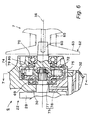
- the lubricating device 84 includes: the oil pan 32 which makes it possible to store the lubricating oil 83 in the inside thereof; and the regulating wall 87 which is arranged between the one side chamber 85 and the other side chamber 86 in the width direction of the body 2 inside this oil pan 32, and this regulating wall 87 is located in substantially the center in the width direction of the body 2 and regulates the lubricating oil 83 flowing between both the chambers 85, 86.
- the lubricating device 84 includes: a pair of left and right oil pumps 90, 90 serving as scavenging pumps which make it possible to draw out the lubricating oil 83 inside the oil pan 32; an oil path 91 which is formed in the cylinder 31 and feeds the lubricating oil 83, which is drawn out by the respective oil pumps 90, into a not-shown lubricating oil tank to store the lubricating oil 83; an oil cooler 92 which is attached to the front surface of the cylinder 31 and cools the lubricating oil 83, which is drawn out by the respective oil pumps 90, through the oil path 91; and a supply oil pump 93 which supplies the lubricating oil 83 stored in the lubricating oil tank to respective lubricated parts of the internal combustion engine 6, and the oil pumps 90 are provided with respect to the one side chamber 85 and the other side chamber 86, respectively, that is, the oil pumps 90 are provided as the left and right pair as described above.
- the oil pumps 90, 93 include: pump casings 97 which are housed inside the one side chambers 85 of both the chambers 85, 86 and form outer shells for each of them and are detachably fastened to the lower surface of the crankcase 30 by fasteners; pump shafts 98 which are born in the respective pump casings 97 so as to be rotatable around an axis extending in the width direction of the body 2; and rotors 99 which are housed in the pump casings 97, respectively, and rotate with the pump shafts 98.
- the pump casings 97 of the respective oil pumps 90 are formed integrally with each other.
- Inlet ports 101 for the lubricating oil 83 into the pump casings 97 of the oil pumps 90 are provided as a pair in the left and right, and these respective inlet ports 101 are opened in the bottom parts of the one side chamber 85 and the other side chamber 86, respectively.
- the respective pump shafts 98 are formed integrally with each other coaxially, the pump shafts 98 are interlockingly coupled to the crank shaft 29 by interlocking means 100 of a chain-wound type, that is, the respective oil pumps 90, 93 are made capable of driving following driving of the internal combustion engine 6.
- the lubricating oil 83 inside the oil pan 32 is drawn out by driving of the respective oil pumps 90 serving as scavenging pumps following the driving of the internal combustion engine 6 and is fed into the lubricating oil tank.
- the lubricating oil 83 in the lubricating oil tank is supplied to respective lubricated parts of the internal combustion engine 6 by driving of the oil pump 93 serving as a supply pump and lubricated, and this lubricating oil 83 after lubrication is returned to the one side chamber 85 and the other side chamber 86 of the oil pan 32 by natural falling.
- the oil pan 32 is detachably fastened to the lower surface of the crankcase 30 by fasteners 103. If the oil pan 32 is removed from the lower surface of the crankcase 30, the respective oil pumps 90, 93 and the lower part of the interlocking means 100 project downward from the lower surface of the crankcase 30, whereby attaching and detaching operations of the interlocking means 100 to and from the pump shafts 98 and maintenance and inspection work for the respective oil pumps 90, 93 and the interlocking means 100 become possible.
- This cooling system 107 which cools the internal combustion engine 6 with cooling water 106.
- This cooling system 107 includes: a water jacket 108 which is formed in the cylinder 31 and the oil cooler 92; a water pump 109 which is disposed above the crank shaft 29 and supported on the cylinder 31 and makes it possible to supply the cooling water 106 to the water jacket 108; gear type interlocking means 110 which interlockingly couples a rotor of this water pump 109 to the balancer shaft 42; and a heat exchanger 111 which is disposed in the vicinity in the rear of the crankcase 30 and air-cools the cooling water 106 after being supplied to the water jacket 108 to cool the vicinity of this water jacket 108, and the water pump 109 operates via the balancer shaft 42 and the interlocking means 110 following the driving of the internal combustion engine 6 in association with the internal combustion engine 6, whereby each part of the internal combustion engine 6 is cooled.
- a battery 115 which supplies electric power to the spark plug 41 of the internal combustion engine 6, the starting motor 45 of the starter 44, a not-shown engine control device, and the like.
- This battery 115 is disposed in a space above the front surface of the cylinder 31, in front of the front surface of this cylinder 31, in front of the balancer shaft 42, and below the air cleaner 50, and is disposed substantially in the center in the width direction of the body 2 and supported in the body 2.
- the air 23 is taken into the cylinder 31 sequentially through the air cleaner 50 of the intake system 25, the carburetor 49, and the inlet passage 37 and, at the same time, the fuel 24 supplied from the carburetor 49 is taken in, and a mixed air of the air 23 and the fuel 24 is ignited and burnt by the spark plug 41 in the cylinder hole 33 in the cylinder 31, and on the other hand, a combustion gas of the mixed air is discharged to the outside of the internal combustion engine 6 as an exhaust 26 sequentially through the exhaust passage 38, the exhaust pipe 53 of the exhaust system 27, and the muffler 54, and the operation of the internal combustion engine 6 is continued.
- the oil pumps 90 are housed only in the one side chamber 85.
- the interlocking means 100 can be commonly used for the respective oil pumps 90, and this interlocking means 100 can be formed with a simple structure, that is, the lubricating device 84 can be formed with a simple structure.
- inlet ports 101 for the lubricating oil 83 into the oil pumps 90 are opened in the one side chamber 85 and the other side chamber 86, respectively.
- the lubricating oil 83 can be drawn out from both the one side chamber 85 and the other side chamber 86 by these oil pumps 90.
- the supply of the lubricating oil 83 to respective lubricated parts of the internal combustion engine 6 by the lubricating device 84 is performed smoothly thereafter.
- oil pumps 90 are provided for the one side chamber 85 and the other side chamber 86, respectively.
- the lubricating oil 83 in the one side chamber 85 and the other side chamber 86 is surely drawn out by the oil pumps 90, respectively.
- the supply of the lubricating oil 83 to respective lubricated parts of the internal combustion engine 6 by the lubricating device 84 is performed more smoothly thereafter.
- the oil pumps 90 are protrudingly provided downward from the lower surface of the crankcase 30.
- both the oil pumps 90, 93 are housed only in the one side chamber 85, the pump shafts 98 of these oil pumps 90, 93 are formed integrally with each other, and the pump shafts 98 are interlockingly coupled to the crank shaft 29 via the interlocking means 100.
- the lubricating device 84 can be formed with a simpler structure.
- the regulating wall 87 may be provided in a plural form and only one oil pump 90 may be provided.
- One aspect of the present invention is a lubricating device in a snowmobile including: drive means which is supported in a body and mounted on a traveling surface and makes it possible to drive the body to travel with a rotational movement thereof; and an internal combustion engine for travel drive which is supported in the body and is interlockingly coupled with the drive means, the internal combustion engine comprising: a crankcase supported in the body; an oil pan which is detachably fixed to this crankcase so as to cover a lower surface side of this crankcase from the underside thereof and stores lubricating oil in the inside thereof; a regulating wall which regulates the lubricating oil flowing between one side chamber and the other side chamber inside this oil pan; oil pumps which make it possible to draw out the lubricating oil inside the oil pan; and interlocking means which interlockingly couples the oil pumps to a crank shaft of the internal combustion engine, wherein the oil pumps are housed in the one side chamber.
- interlocking means can be commonly used for the respective oil pumps, and this interlocking means can be formed with a simple structure, that is, the lubricating device can be formed with a simple structure.
- the inlet ports for the lubricating oil into the oil pumps are opened in the one side chamber and the other side chamber, respectively.
- the lubricating oil can be drawn out from both the one side chamber and the other side chamber by these oil pumps.
- the supply of the lubricating oil to respective lubricated parts of the internal combustion engine by the lubricating device is performed smoothly thereafter.
- the second aspect of the present invention is a lubricating device in a snowmobile, wherein the oil pumps are protrudingly provided downward from the lower surface of the crankcase.
- the internal combustion engine includes: a crankcase supported in the body; an oil pan which is detachably fixed to this crankcase so as to cover a lower surface side of this crankcase from the underside thereof and stores lubricating oil in the inside thereof; a regulating wall which regulates the lubricating oil flowing between one side chamber and the other side chamber inside this oil pan; oil pumps which make it possible to draw out the lubricating oil inside the oil pan; and interlocking means which interlockingly couples these oil pumps to a crank shaft of the internal combustion engine.
- an internal combustion engine 6 includes: an oil pan 32 which is detachably fixed to this crankcase 30 so as to cover a lower surface side of this crankcase 30 from the underside thereof and stores lubricating oil 83 in the inside thereof; a regulating wall 87 which regulates the lubricating oil 83 flowing between one side chamber 85 and the other side chamber 86 inside this oil pan 32; oil pumps 90 which make it possible to draw out the lubricating oil 83 inside the oil pan 32; and interlocking means 100 which interlockingly couples the oil pumps 90 to a crank shaft 29 of the internal combustion engine 6.
- the oil pumps 90 are housed in the one side chamber 85 and inlet ports 101 for the lubricating oil 83 into the oil pumps 90 are opened in the one side chamber 85 and the other side chamber 86
Landscapes
- Engineering & Computer Science (AREA)
- Mechanical Engineering (AREA)
- General Engineering & Computer Science (AREA)
- Lubrication Details And Ventilation Of Internal Combustion Engines (AREA)
- Lubrication Of Internal Combustion Engines (AREA)
Applications Claiming Priority (2)
| Application Number | Priority Date | Filing Date | Title |
|---|---|---|---|
| JP2002246409 | 2002-08-27 | ||
| JP2002246409A JP2004084553A (ja) | 2002-08-27 | 2002-08-27 | スノーモービルにおける潤滑装置 |
Publications (3)
| Publication Number | Publication Date |
|---|---|
| EP1394371A2 true EP1394371A2 (fr) | 2004-03-03 |
| EP1394371A3 EP1394371A3 (fr) | 2004-08-18 |
| EP1394371B1 EP1394371B1 (fr) | 2006-10-18 |
Family
ID=31492530
Family Applications (1)
| Application Number | Title | Priority Date | Filing Date |
|---|---|---|---|
| EP03019301A Expired - Lifetime EP1394371B1 (fr) | 2002-08-27 | 2003-08-26 | Pompe de graissage placée dans le carter à huile |
Country Status (4)
| Country | Link |
|---|---|
| US (1) | US7007655B2 (fr) |
| EP (1) | EP1394371B1 (fr) |
| JP (1) | JP2004084553A (fr) |
| CA (1) | CA2438495C (fr) |
Cited By (3)
| Publication number | Priority date | Publication date | Assignee | Title |
|---|---|---|---|---|
| US8276700B2 (en) | 2009-10-26 | 2012-10-02 | Yamaha Hatsudoki Kabushiki Kaisha | Snowmobile |
| US8763745B2 (en) | 2009-10-26 | 2014-07-01 | Yamaha Hatsudoki Kabushiki Kaisha | Snowmobile |
| AT514563B1 (de) * | 2013-10-01 | 2015-02-15 | Steyr Motors Gmbh | Verbrennungskraftmaschine mit einem Saugfuß im Kurbelgehäuse |
Families Citing this family (10)
| Publication number | Priority date | Publication date | Assignee | Title |
|---|---|---|---|---|
| JP2004084551A (ja) * | 2002-08-27 | 2004-03-18 | Yamaha Motor Co Ltd | 鞍乗型乗り物における駆動装置 |
| US7165651B2 (en) * | 2003-10-09 | 2007-01-23 | Kawasaki Jukogyo Kabushiki Kaisha | Lubricating structure of an engine for vehicle |
| JP2005163570A (ja) * | 2003-12-01 | 2005-06-23 | Ihara Seisakusho:Kk | 内燃機関の潤滑装置 |
| CN101784760B (zh) | 2007-06-22 | 2013-08-07 | 庞巴迪动力产品公司 | 具有电控润滑的雪地机动车 |
| DE102007053718B4 (de) * | 2007-11-10 | 2013-12-05 | Audi Ag | Brennkraftmaschine mit einer Pumpe für ein flüssiges Medium |
| JP5232842B2 (ja) * | 2010-09-16 | 2013-07-10 | 株式会社山田製作所 | 可変流量オイルポンプ |
| JP5904408B2 (ja) * | 2012-06-14 | 2016-04-13 | 本田技研工業株式会社 | パワーユニットの潤滑装置 |
| JP5741563B2 (ja) * | 2012-12-06 | 2015-07-01 | トヨタ自動車株式会社 | 動力伝達装置 |
| DE102021207694A1 (de) * | 2021-07-19 | 2023-01-19 | Brose Fahrzeugteile SE & Co. Kommanditgesellschaft, Würzburg | Schmiermittelversorgungssystem für ein Kraftfahrzeug sowie Pumpe für ein solches Schmiermittelversorgungssystem |
| US12286924B2 (en) * | 2022-08-19 | 2025-04-29 | Brp-Rotax Gmbh & Co. Kg | Internal combustion engine and lubrication system thereof |
Family Cites Families (20)
| Publication number | Priority date | Publication date | Assignee | Title |
|---|---|---|---|---|
| US5024287A (en) * | 1987-03-31 | 1991-06-18 | Yamaha Hatsudiki Kabushiki Kaisha | Engine unit for vehicle |
| JPS6473108A (en) | 1987-09-16 | 1989-03-17 | Honda Motor Co Ltd | Lubricating oil reservoir partitioning structure for engine |
| US4915070A (en) * | 1988-03-31 | 1990-04-10 | Yamaha Hatsudoki Kabushiki Kaisha | Engine unit for motor vehicle |
| US5240088A (en) * | 1988-11-14 | 1993-08-31 | Yamaha Hatsudoki Kabushiki Kaisha | Engine construction for vehicle |
| DE4206068A1 (de) * | 1991-03-01 | 1992-09-03 | Mazda Motor | Aufbau einer motoreinheit eines fahrzeugs |
| JPH07237587A (ja) * | 1994-02-28 | 1995-09-12 | Sanshin Ind Co Ltd | 水上滑走艇 |
| JPH09301286A (ja) * | 1996-03-15 | 1997-11-25 | Yamaha Motor Co Ltd | ウォータビークルのオイルフィルタ配置構造 |
| DE19619977C2 (de) * | 1996-05-17 | 1998-07-02 | Daimler Benz Ag | Ölwanne für eine Brennkraftmaschine |
| JPH09317426A (ja) * | 1996-05-31 | 1997-12-09 | Yamaha Motor Co Ltd | 小型艇のエンジン潤滑装置 |
| US5669464A (en) * | 1996-12-10 | 1997-09-23 | Caterpillar Inc. | System for automatically controlling engine lubricating fluid flow |
| DE19860381A1 (de) * | 1998-12-28 | 2000-06-29 | Hatz Motoren | Ölansaugsystem für eine Brennkraftmaschine, insbesondere einen Einzylinder-Dieselmotor |
| US6314934B1 (en) * | 1999-09-04 | 2001-11-13 | Honda Giken Kogyo Kabushiki Kaisha | Lubricating device for internal combustion engine |
| JP2001073737A (ja) * | 1999-09-05 | 2001-03-21 | Honda Motor Co Ltd | 内燃機関用オイルタンク |
| DE10002256B4 (de) | 2000-01-20 | 2008-06-26 | Daimler Ag | Vorrichtung zur Beeinflussung der Erwärmung des Schmieröls einer Brennkraftmaschine |
| JP2002364328A (ja) * | 2000-09-20 | 2002-12-18 | Sanshin Ind Co Ltd | 小型船舶用エンジンのベンチレーションシステム |
| DE10105435A1 (de) | 2001-02-07 | 2002-08-29 | Porsche Ag | Ölauffangvorrichtung für eine Brennkraftmaschine |
| JP4446622B2 (ja) * | 2001-03-27 | 2010-04-07 | トヨタ紡織株式会社 | 内燃機関用オイルポンプ及びその使用方法 |
| US6601557B1 (en) * | 2001-09-07 | 2003-08-05 | General Motors Corporation | Engine oil pump and balance shaft module |
| US6742491B1 (en) * | 2002-12-17 | 2004-06-01 | Tecumseh Products Company | Engine lubrication system |
| US6786188B1 (en) * | 2003-05-15 | 2004-09-07 | Kawasaki Jukogyo Kabushiki Kaisha | Dry-sump lubrication type four-stroke cycle engine |
-
2002
- 2002-08-27 JP JP2002246409A patent/JP2004084553A/ja active Pending
-
2003
- 2003-08-25 US US10/647,693 patent/US7007655B2/en not_active Expired - Lifetime
- 2003-08-26 EP EP03019301A patent/EP1394371B1/fr not_active Expired - Lifetime
- 2003-08-27 CA CA002438495A patent/CA2438495C/fr not_active Expired - Lifetime
Cited By (5)
| Publication number | Priority date | Publication date | Assignee | Title |
|---|---|---|---|---|
| US8276700B2 (en) | 2009-10-26 | 2012-10-02 | Yamaha Hatsudoki Kabushiki Kaisha | Snowmobile |
| US8763745B2 (en) | 2009-10-26 | 2014-07-01 | Yamaha Hatsudoki Kabushiki Kaisha | Snowmobile |
| AT514563B1 (de) * | 2013-10-01 | 2015-02-15 | Steyr Motors Gmbh | Verbrennungskraftmaschine mit einem Saugfuß im Kurbelgehäuse |
| AT514563A4 (de) * | 2013-10-01 | 2015-02-15 | Steyr Motors Gmbh | Verbrennungskraftmaschine mit einem Saugfuß im Kurbelgehäuse |
| DE102014112866A1 (de) | 2013-10-01 | 2015-04-02 | Steyr Motors Gmbh | Verbrennungskraftmaschine mit einem Saugfuß im Kurbelgehäuse |
Also Published As
| Publication number | Publication date |
|---|---|
| JP2004084553A (ja) | 2004-03-18 |
| US20040040531A1 (en) | 2004-03-04 |
| EP1394371B1 (fr) | 2006-10-18 |
| US7007655B2 (en) | 2006-03-07 |
| CA2438495A1 (fr) | 2004-02-27 |
| CA2438495C (fr) | 2009-03-24 |
| EP1394371A3 (fr) | 2004-08-18 |
Similar Documents
| Publication | Publication Date | Title |
|---|---|---|
| JP4384457B2 (ja) | エンジン | |
| JP2002266653A (ja) | 雪上車 | |
| EP1394371B1 (fr) | Pompe de graissage placée dans le carter à huile | |
| WO2000035743A2 (fr) | Moteur pour deux-roues | |
| JP3891756B2 (ja) | 内燃機関の潤滑構造 | |
| JP2004084552A (ja) | スノーモービルにおける構成部品配設構造 | |
| CN102003263B (zh) | 动力单元的冷却装置 | |
| EP1396420B1 (fr) | Amortisseur de torsion pour véhicules du type à selle | |
| JP2011105148A (ja) | 車両用パワーユニット | |
| JP7127376B2 (ja) | 車両 | |
| US5687680A (en) | Valve system for overhead valve internal combustion engine | |
| JP3470355B2 (ja) | ドライサンプエンジンのオイル通路 | |
| JP3184040B2 (ja) | 4サイクル内燃機関のカム駆動部材潤滑装置 | |
| JPH0828236A (ja) | 内燃機関のカム摺動面潤滑構造 | |
| JP4467916B2 (ja) | 内燃機関のブリーザ装置 | |
| JP4556611B2 (ja) | 自動二輪車のパワーユニット | |
| JP2002122013A (ja) | エンジンの潤滑装置 | |
| JP7380924B2 (ja) | 内燃機関 | |
| EP2031211A2 (fr) | Moteur et véhicule de type chariot cavalier | |
| JP3805506B2 (ja) | ドライサンプ潤滑式4サイクルエンジンユニット | |
| JPH0763024A (ja) | ドライサンプ式自動二輪車用エンジン | |
| JP2005351115A (ja) | 内燃機関のオイルポンプ取り付け構造 | |
| JP2005291052A (ja) | 内燃機関の潤滑構造 | |
| JP2003307155A (ja) | クランクケースおよびその潤滑構造 | |
| JPH10329553A (ja) | 鞍乗型車両用駆動装置 |
Legal Events
| Date | Code | Title | Description |
|---|---|---|---|
| PUAI | Public reference made under article 153(3) epc to a published international application that has entered the european phase |
Free format text: ORIGINAL CODE: 0009012 |
|
| AK | Designated contracting states |
Kind code of ref document: A2 Designated state(s): AT BE BG CH CY CZ DE DK EE ES FI FR GB GR HU IE IT LI LU MC NL PT RO SE SI SK TR |
|
| AX | Request for extension of the european patent |
Extension state: AL LT LV MK |
|
| PUAL | Search report despatched |
Free format text: ORIGINAL CODE: 0009013 |
|
| AK | Designated contracting states |
Kind code of ref document: A3 Designated state(s): AT BE BG CH CY CZ DE DK EE ES FI FR GB GR HU IE IT LI LU MC NL PT RO SE SI SK TR |
|
| AX | Request for extension of the european patent |
Extension state: AL LT LV MK |
|
| RIC1 | Information provided on ipc code assigned before grant |
Ipc: 7F 01M 1/02 B Ipc: 7F 01M 11/00 A |
|
| 17P | Request for examination filed |
Effective date: 20050215 |
|
| AKX | Designation fees paid |
Designated state(s): FI SE |
|
| REG | Reference to a national code |
Ref country code: DE Ref legal event code: 8566 |
|
| RBV | Designated contracting states (corrected) |
Designated state(s): FI SE |
|
| GRAP | Despatch of communication of intention to grant a patent |
Free format text: ORIGINAL CODE: EPIDOSNIGR1 |
|
| GRAS | Grant fee paid |
Free format text: ORIGINAL CODE: EPIDOSNIGR3 |
|
| GRAA | (expected) grant |
Free format text: ORIGINAL CODE: 0009210 |
|
| AK | Designated contracting states |
Kind code of ref document: B1 Designated state(s): FI SE |
|
| REG | Reference to a national code |
Ref country code: SE Ref legal event code: TRGR |
|
| PLBE | No opposition filed within time limit |
Free format text: ORIGINAL CODE: 0009261 |
|
| STAA | Information on the status of an ep patent application or granted ep patent |
Free format text: STATUS: NO OPPOSITION FILED WITHIN TIME LIMIT |
|
| 26N | No opposition filed |
Effective date: 20070719 |
|
| PGFP | Annual fee paid to national office [announced via postgrant information from national office to epo] |
Ref country code: FI Payment date: 20090813 Year of fee payment: 7 Ref country code: SE Payment date: 20090806 Year of fee payment: 7 |
|
| EUG | Se: european patent has lapsed | ||
| PG25 | Lapsed in a contracting state [announced via postgrant information from national office to epo] |
Ref country code: FI Free format text: LAPSE BECAUSE OF NON-PAYMENT OF DUE FEES Effective date: 20100826 |
|
| PG25 | Lapsed in a contracting state [announced via postgrant information from national office to epo] |
Ref country code: SE Free format text: LAPSE BECAUSE OF NON-PAYMENT OF DUE FEES Effective date: 20100827 |