EP1394418A2 - Compresseur à palettes - Google Patents
Compresseur à palettes Download PDFInfo
- Publication number
- EP1394418A2 EP1394418A2 EP03255164A EP03255164A EP1394418A2 EP 1394418 A2 EP1394418 A2 EP 1394418A2 EP 03255164 A EP03255164 A EP 03255164A EP 03255164 A EP03255164 A EP 03255164A EP 1394418 A2 EP1394418 A2 EP 1394418A2
- Authority
- EP
- European Patent Office
- Prior art keywords
- high pressure
- pressure oil
- oil
- passage
- vanes
- Prior art date
- Legal status (The legal status is an assumption and is not a legal conclusion. Google has not performed a legal analysis and makes no representation as to the accuracy of the status listed.)
- Granted
Links
- 238000004891 communication Methods 0.000 claims abstract description 28
- 238000007906 compression Methods 0.000 claims description 40
- 230000006835 compression Effects 0.000 claims description 39
- 239000003507 refrigerant Substances 0.000 claims description 19
- 230000002093 peripheral effect Effects 0.000 claims description 15
- 230000007704 transition Effects 0.000 claims description 14
- 230000001050 lubricating effect Effects 0.000 claims description 3
- 244000145845 chattering Species 0.000 abstract description 9
- 239000012530 fluid Substances 0.000 description 12
- 238000010276 construction Methods 0.000 description 9
- 230000001603 reducing effect Effects 0.000 description 5
- 230000000694 effects Effects 0.000 description 4
- 238000004378 air conditioning Methods 0.000 description 3
- 230000007423 decrease Effects 0.000 description 3
- 238000000034 method Methods 0.000 description 3
- 239000000446 fuel Substances 0.000 description 2
- 230000006866 deterioration Effects 0.000 description 1
- 230000003292 diminished effect Effects 0.000 description 1
- 238000007599 discharging Methods 0.000 description 1
- 238000007789 sealing Methods 0.000 description 1
- 238000000926 separation method Methods 0.000 description 1
Images


Classifications
-
- F—MECHANICAL ENGINEERING; LIGHTING; HEATING; WEAPONS; BLASTING
- F01—MACHINES OR ENGINES IN GENERAL; ENGINE PLANTS IN GENERAL; STEAM ENGINES
- F01C—ROTARY-PISTON OR OSCILLATING-PISTON MACHINES OR ENGINES
- F01C21/00—Component parts, details or accessories not provided for in groups F01C1/00 - F01C20/00
- F01C21/08—Rotary pistons
- F01C21/0809—Construction of vanes or vane holders
- F01C21/0818—Vane tracking; control therefor
- F01C21/0854—Vane tracking; control therefor by fluid means
- F01C21/0872—Vane tracking; control therefor by fluid means the fluid being other than the working fluid
Definitions
- the present invention relates to a gas compressor suitable for automotive air conditioning or the like and adapted to suck, compress, and discharge refrigerant gas.
- Figs. 10 and 11 show an example of a gas compressor for use in automotive air conditioning or the like.
- This compressor is equipped with a cylinder 5 with an elliptical inner periphery, and a front side block 6 and a rear side block 7 arranged at the axial ends of the cylinder 5.
- a rotor 11 is arranged so as to be rotatable around a rotor shaft 10.
- a plurality of vane grooves 12 are formed so as to extend from the outer peripheral surface to the inner periphery of the rotor 11, and vanes 15 are respectively accommodated in the vane grooves 12 so as to be capable of projecting from and retracting into the vane grooves.
- each vane groove 12 Formed at the bottom portion (inner peripheral side) of each vane groove 12 is a back pressure chamber 14 to which pressure fluid is supplied.
- the vanes 15 are caused to project toward the outer periphery by the pressure of the pressure fluid supplied to the back pressure chambers 14 and the centrifugal force generated by the rotation of the rotor 11, slidably abutting the inner peripheral surface of the cylinder.
- the outer peripheral surface of the rotor 11, the vanes 15 projecting from the outer peripheral surface of the rotor 11 to abut the inner surface of the cylinder, and the inner peripheral surface of the cylinder 5 define a plurality of cylinder compression chambers 16. This is how the compressor main body is constructed.
- the volume of the cylinder compression chambers 16 is varied, thereby compressing refrigerant gas in the cylinder compression chambers 16.
- the compressed refrigerant is discharged from the cylinder compression chambers 16 into an oil separating block 25 .
- the refrigerant gas gets mixed with oil inside the gas compressor, and is discharged into the oil separating block 25 while containing the oil, which is separated from the refrigerant gas by an oil separator 26 provided in the oil separating block 25 .
- the separated oil is dripped into an oil sump 30 to stay therein, and the compressed gas from which the oil has been removed is discharged into a second discharge chamber 8.
- the vane back pressure is controlled in the course of suction, compression, and discharge strokes such that the vane back pressure is an middle pressure from the suction to compression stroke and high pressure in the discharge stroke.
- the reason for this is as follows. During the period in which the compression of the refrigerant gas trapped in the cylinder compression chambers 16 by means of the vanes 15 is so progressed as to attain the discharging stage, that is, in the discharge process, a strong force due to the increase in the pressure of the refrigerant gas in the cylinder compression chambers 16 is exerted so as to push the vanes 15 back toward the interior of the vane grooves 12 .
- high pressure oil supplying holes 18 corresponding in position and configuration to the back pressure chambers 14 of the vanes 15 in the discharge stroke, and high pressure oil which has not been throttled is supplied to the high pressure oil supplying holes 18 through the oil passage 31.
- high pressure oil is supplied from the high pressure oil supplying holes 18 to the back pressure chambers 14. Due to the supply of the high pressure oil to the back pressure chambers 14 through the high pressure oil supplying holes 18, high pressure is maintained in the back pressure chambers 14, and high pressure is imparted to the vanes 15, thereby reliably bringing the vanes 15 into contact with the inner surface of the cylinder 5.
- the flat groove portions 17 and the high pressure oil supplying holes 18 are situated such that communication is temporarily established therebetween through the back pressure chambers 14 as the rotor 11 rotates.
- the pressure of the high pressure oil remains in the flat groove portions 17, so that the pressure in the back pressure chambers 14 is kept high even in the suction and compression strokes, which means the power reducing effect cannot be achieved to a sufficient degree.
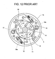
- a design has been made in which, as shown in Fig.
- high pressure oil supplying holes 18a are arranged in a positional relationship such that no communication is established with the flat groove portions 17 through the backpressure chambers 14 so that the influence of the high pressure oil in the high pressure oil supplying holes may not be exerted on the flat groove portions 17. Due to this improvement, there is no fear of the high pressure oil supplied from the high pressure oil supplying holes 18a flowing directly into the flat groove portions 17, whereby the pressure in the back pressure chambers 14 is reduced to a sufficient degree in the suction and compression strokes, making it possible to reliably obtain the power consumption reduction effect during normal operation.
- Thepresent invention has beenmade inviewof the above problems . It is an object of the present invention to provide a gas compressor which supplies sufficiently high pressure to the back pressure chambers at the start or during low speed operation to thereby improve the vane projectability and which makes it possible to supply low pressure during normal operation to thereby obtain a power reducing effect.
- the invention relates to a gas compressor having a compressor main body which sucks, compresses, and discharges refrigerant gas, and an oil sump which stores oil for lubricating the compressor main body, the compressor main body being composed of a cylinder, side blocks arranged at axial ends of the cylinder, a rotor rotatably arranged in the cylinder, vane grooves formed so as to extend from an outer peripheral surface of the rotor to an inner periphery thereof, and vanes accommodated in the vane grooves so as to be capable of advancing and retracting, the gas compressor comprising: a back pressure space including the bottom portions of the vane grooves and attaining middle pressure between a suction pressure and a discharge pressure during a normal operation of the compressor main body; a first high pressure oil passage establishing communication between the oil sump and the vane groove bottom portions when the vanes are at their discharge stroke positions; a second high pressure oil passage establishing communication between the
- the opening/closing valve keeps the second high pressure oil passage open when the rotation of the compressor main body is at rest, closes the second high pressure oil passage when the compressor main body starts rotation, and keeps the second high pressure oil passage closed during a normal operation of the compressor main body.
- the opening/closing valve keeps the second high pressure oil passage closed during the normal operation of the compressor main body and keeps it open when the compressor main body is not performing the normal operation and the oil pressure is low.
- the back pressure space has a flat groove communicating with the vane groove bottom portions when the vanes are at their positions in transition from suction to compression stroke, and that the vane groove bottom portions communicate with the first high pressure oil passage after the communication between the flat groove and the vane groove bottom portions is interrupted.
- a downstream end portion of the second high pressure oil passage opens into the vane groove bottom portions, with the vanes being situated at their discharge stroke positions.
- the downstream end portion of the second high pressure oil passage opens into the flat groove.
- the opening/closing valve is movably arranged so as to open and close the second high pressure oil passage and has a valve element situated at a position where the valve element closes the flow passage and an elastic member capable of imparting an elastic force to the valve element to place the valve element at a position where the valve element opens the passage, the valve element moving under a pressure of high pressure oil to a position where the valve element closes the flow passage during normal operation of the compressor and moving to a position where the valve element opens the flow passage by the elastic force of the elastic member with the pressure of the high pressure oil being lowered.
- a differential pressure of the high pressure oil to which the discharge pressure in the compressor is imparted and a middle pressure oil is applied to the valve element.
- the opening/closingvalve in a state in which the oil pressure is not sufficiently high as in the case of starting, the opening/closingvalve is opened, whereby high pressure fluid is supplied to the back pressure chambers through the second high pressure oil passage in the process of imparting middle pressure during normal operation.
- the pressure in the vane back pressure chambers increases to enhance the vane extruding force. This helps to improve the vane projectability at the start of the compressor, enabling the vanes to overcome the resistance of the oil film to quickly project from the vane grooves and making it possible to start normal compression at an early stage, whereby the operation of the air conditioning system is expedited, and cool air can be quickly provided.
- the vanes are reliably brought into contact with the cylinder inner surface, and chattering caused by collision of vanes is prevented, thus achieving an improvement in terms of quietness for the vehicle in which the compressor is mounted.
- the opening/closing valve prefferably be one which is closed during normal operation and which is opened under an oil pressure not sufficiently high as is the case when starting the compressor or operating it at low speed.
- the second high pressure oil passage is one adapted to receive supply of high pressure oil from a high pressure oil supply source (oil sump or the like) in the gas compressor, and, regarding the position, etc. of the supply source, there are no particular limitations in the present invention. Further, it may also be one connected to the first high pressure oil passage to thereby receive supply of high pressure oil from that passage. Further, it is naturally possible for the second high pressure oil passage to be provided independently of the first high pressure oil passage. Further, it is possible for the second high pressure oil passage to be one connected to the space inside the cylinder to supply high pressure oil in the space inside the cylinder.
- the above-mentioned middle pressure oil may be one obtained through passage of high pressure oil between the rotor shaft for rotating the rotor and the bearing rotatably supporting the rotor shaft.
- the opening/closing valve is only necessary for the opening/closing valve to be one capable of opening and closing the second high pressure oil passage during normal operation and in the periods other than that, and there are no limitations in the present invention regarding its structure. While, as stated above, the structure of the opening/closing valve is not restricted to the above-described one, it may, for example, be preferably one in which the valve element thereof moves (slides or rotates) through appropriate balancing between the elastic force of an elastic member and the pressure of the high pressure oil (or the differential pressure of the high pressure oil and the middle pressure oil) to thereby open and close the above-mentioned passage.
- the pressure of the high pressure oil varies according to the operating condition of the compressor main body, so that it is possible to perform opening/closing control on the opening/closing valve by setting the elastic force such that during normal operation, the pressure of the high pressure oil overcomes the elastic member and that in the conditions other than that, in which the pressure of the high pressure oil has not been increased to a sufficient degree yet, the elastic force of the elastic member is predominant.
- the differential pressure between the high pressure oil and the middle pressure oil also varies according to the operating condition of the compressor main body, so that it is possible to perform opening/closing control on the opening/closing valve according to the operating condition of the compressor main body by setting the elastic force such that during normal operation, the differential pressure is large enough to overcome the elastic force, and that in the conditions other than that, in which the oil pressure has not been increased to a sufficient degree yet, the differential pressure is so diminished as to be overcome by the elastic force of the elastic member.
- the fluid supplied to the back pressure chambers as.the high pressure oil and the middle pressure oil imparted to the opening/closing valve. Instead, it is also possible to use the fluid obtained within the gas compressor.
- the pressure of the fluid may also be different from the pressure of the fluid supplied to the back pressure chambers.
- the elastic member is a coil spring, this should not be construed restrictively. Further, the compressive force, extension force, etc. of the elastic member may be appropriate ones, and there are not particular limitations regarding the mode in which it is used.
- the gas compressor of the present invention includes a cylinder, side blocks arranged at the axial ends of the cylinder, a rotor rotatably arranged in the cylinder, vane grooves extending from the outer peripheral surface to the inner periphery of the rotor, vanes accommodated in the vane grooves so as to be capable of advancing and retracting, and back pressure chambers provided in the vane grooves and adapted to impart extruding force to the vanes. This is how the gas compressormainbody is constructed.
- the gas compressor of the present invention may further include a suction chamber into which lowpressure refrigerant gas is introduced, a suction passage through which the low pressure refrigerant gas is sucked into the cylinder compression chamber from the suction chamber, a discharge hole through which the compressed refrigerant gas is discharged from the cylinder compression chambers, a discharge chamber into which the refrigerant gas is discharged through the discharge hole, an oil sump receiving the pressure of the discharge chamber, and an oil communication passage communicating with the oil sump.
- the gas compressor of the present invention is equipped with a cylinder 5 with an elliptical inner periphery, and front and rear side blocks 6 and 7 arranged at the axial ends of the cylinder 5.
- a front housing 1a is mounted to the front side of the front side block 6, and a rear housing 1b is mounted so as to extend from the rear side of the rear side block 7 to the front side block 6.
- a suction port 2 is provided in the front housing 1a, and a suction chamber 3 is provided in the front housing 1a so as to communicate with the suction port 2.
- a rotor 11 is arranged in the cylinder 5 so as to be rotatable around the rotor shaft 10.
- a plurality of vane grooves 12 are formed so as to extend from outer peripheral surface toward inner periphery of the rotor 11, with vanes 15 being accommodated in the vane grooves 12 so as to be capable of projecting and retracting.
- the cylinder compression chambers 16 communicate with the suction chamber 3 through the suction passage 4 formed in the front side block 6. Further, formed in the cylinder 5 is a discharge hole 20 communicating with the cylinder compression chambers 16, and a first discharge chamber 21 communicating with the discharge hole 20 is formed along the axial direction of the cylinder 5. Reference numeral 22 indicates a reedvalve for opening and closing the discharge hole 20.
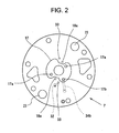
- the first discharge chamber 21 communicates with an oil separating block 25 provided on the rear side of the rear side block 7 through a discharge passage 23 formed in the rear side block 7 (see Fig. 2), with an oil separator 26 being provided in the oil separating block 25.
- the space defined by the rear side block 7 and the interior of the rear housing 1b constitutes a second discharge chamber 8 into which compressed gas (refrigerant) is discharged, and an oil sump 30 is provided in the lower portion of the second discharge chamber 8.
- the oil sump 30 communicates with an oil passage 31, which is arranged inside the gas compressor to supply oil to various parts thereof.
- the oil passage 31 communicates with a lowpressure portion formed by the gap etc between the rotor shaft 10 and a bearing 10a rotatably supporting the same.
- Flat groove portions 17 are respectively formed in the end surfaces of the front side block 6 and the rear side block 7, and low pressure oil supplying holes 17a open into the flat groove portions 17 shown by Fig.3, the supplying holes 17a communicating with the bearing 10a through an oil supplying passage.
- the configuration and arrangement positions of the flat groove portions 17 are determined such that they communicate with the vane back pressure chambers 14 in the suction and compression strokes of the vanes 15 depending upon the rotating position of the rotor 11.
- the other portion of the oil passage 31 communicates with high pressure oil supplying holes 18a formed in the inner surface of the rear side block 7 so that oil may be supplied without passing through the gap between the rotor shaft 10 and the bearing.
- the section from the oil sump 30 side opening of the oil passage 31 to the high pressure oil supplying holes 18a constitutes a first high pressure oil passage.
- the configuration and arrangement positions of the high pressure oil supplying holes 18a are determined such that they communicate with the vane back pressure chambers 14 in the discharge stroke of the vanes 15 depending upon the rotating position of the rotor 11. Further, the flat groove portions 17 and the high pressure oil supplying holes 18a are formed in a positional relationshipwhichestablishes no communication between them through the back pressure chambers 14 rotating with the rotation of the rotor 11.
- a part of the oil passage 31 forming a high pressure oil supplying support passage 32 as a second high pressure oil passage extends on the inner surface side of the rear side block, and the forward end thereof opens in the inner surface of the rear side block as a high pressure oil supplying support hole 33.
- the high pressure oil supplying support hole 33 is formed at a position where it communicates with the flat groove portions 17 through the back pressure chambers 14 when the back pressure chambers 14 rotate.
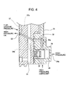
- the high pressure oil supplying support passage 32 has in the oil separating block 25 a valve hole 34 extending in a direction crossing the supplying passage 32, and a spool-shaped spool valve element 35 with a communication groove 35a in the outer peripheral surface thereof is arranged movably in the valve hole 34.
- a high pressure oil supplying passage 34a Connected to the valve hole 34 on one end surface side of the spool valve element 35 is a high pressure oil supplying passage 34a so that the pressure of high pressure oil may be imparted thereto, and connected to the valve hole 34 on the other end surface side of the spool valve element 35 is a middle pressure oil intake passage 34b communicating with a middle pressure oil intake hole 17b open into the flat groove portions 17.
- the differential pressure of the high pressure oil and the middle pressure oil is applied to the spool valve element 35. Further, a coil spring 37 imparting an elastic force to the spool valve element 35 against the high oil pressure is arranged in the valve hole 34 as an elastic member.
- the opening/closing valve of the present invention is constructed as described above.
- the spool valve element 35 of the opening/closing valve moves to a position where the high pressure oil supplying support passage 32 is opened by the elastic force of the coil spring 37, that is, the position where communication is established between the high pressure oil supplying support passage 32 and the communication groove 35a. Due to this communication, high pressure oil is supplied to the high pressure oil supplying support hole 33 through the high pressure oil supplying support passage 32.
- middle pressure oil is supplied from the flat groove portions 17 to the back pressure chambers 14 during the transition of the vanes from the suction to the compression stroke, and, in the discharge stroke, high pressure oil is supplied from the high pressure oil supplyingholes 18a to the backpressure chambers 14. Further, during the transition from the compression to the discharge stroke, high pressure oil is supplied from the high pressure oil supplying support hole 33 to the back pressure chambers 14. At this time, the back pressure chambers 14 temporarily communicate with the high pressure oil supplying support hole 33, and also with the flat groove portions 17, with communication being established between the high pressure oil supplying support hole 33 and the flat groove portions 17 through the back pressure chambers 14.
- the refrigerant gas thus compressed in the cylinder compression chambers 16 is discharged in the discharge stroke through the discharge holes 20 to the exterior of the cylinder compression chambers 16, and discharged to the oil separating block 25 through the first discharge chambers 21. Thereafter, as in the prior art, oil is separated by the oil separator 26, and discharged into the discharge chamber 8, and, further, discharged into external piping through the discharge port 9 .
- the oil separated by the oil separator 26 gathers in the oil sump 30, and attains high pressure under the pressure of the refrigerant gas discharged as described above before it is supplied to various portions of the gas compressor through the oil passage 31.
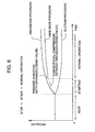
- Fig. 6 is a graph showing changes in discharge pressure, back pressure chamber pressure, and suction pressure in the above-described gas compressor and a conventional gas compressor.
- the back pressure chamber pressure shown is that in the suction and compression stroke.
- the discharge pressure and the back pressure chamber pressure increase gradually from the start.
- the pressure in the back pressure chambers is not sufficient, and the problem as mentioned above is involved.
- the discharge pressure and the back pressure increase similarly from the start by the operation of the opening/closing valve, and there is little or no difference in pressure between them.
- the pressure of the back pressure chambers gradually decreases by closing the opening/closing valve, so that, during normal operation, a back pressure chamber pressure equal to that of the conventional gas compressor is attained.
- the pressure in the back pressure chambers increases to increase the extruding force for the vanes; upon transition to normal operation, the back pressure chamber pressure for the vanes decreases, making it possible to obtain a power reducing effect as in the prior art.
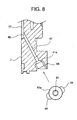
- a high pressure oil supplying support passage 41 to which high pressure oil is supplied, is connected to the high pressure oil supplying support hole 40, forming the second high pressure oil passage.
- a ball valve element 42 movable along the high pressure oil supplying support passage 41.
- the opening and closing of the high pressure oil supplying support passage 41 are effected.
- a coil spring 43 which has an elastic force to be applied to the ball valve element 42 so as to move the ball valve element 42 away from the conical portion 41a.
- the pressure of the oil in the flat groove portions 17 is applied to one end surface side (flat groove portion side) of the ball valve element 42, and the pressure of the high pressure oil is applied to the other end surface side thereof.
- the opening/closing valve is constructed as described above.
- a flow support passage 44 (see Fig. 8) extending along the high pressure oil supplying support passage 41, and viscous oil passes around the ball valve element 42 to smoothly flow to the flat groove portion 17 side.
- the high pressure oil and the low pressure oil are of equal pressure or exhibit little difference in pressure between them at the start and during low speed operation, so that the ball valve element 42 is separated from the conical portion 41a to move to the position where the high pressure oil supplying support passage 41 is opened (see Fig. 9B). Due to this communication, high pressure oil is supplied to the flat groove portions 17 through the high pressure oil supplying support passage 41, whereby even during transition of the vanes from the suction to the compression stroke, high pressure oil is supplied from the flat groove portions 17 to the back pressure chambers 14, and the extruding force for the vanes is enhanced, with the projectability of the vanes 15 being improved. Further, due to the enhancement of the extruding force, it is also possible to prevent noise generation due to chattering.
- the supply of high pressure oil in the high pressure oil supplying support portion is effected from an appropriate oil supplying passage
- the supply source for example, it is also possible to use high pressure oil accumulated in the cylinder compression chambers as the supply source.
- the gas compressor having the compressor main body which sucks, compresses, and discharges refrigerant gas, and the oil sump for storing oil for lubricating the compressor main body
- the compressor main body is composed of the cylinder, the side blocks arranged at the axial ends of the cylinder, the rotor rotatably arranged in the cylinder, the vane grooves formed so as to extend from the outer peripheral surface to the inner periphery of the rotor, and the vanes accommodated in the vane grooves so as to be capable of advancing and retracting
- the compressor main body including: the back pressure chambers including the bottom portions of the vane grooves and attaining the middle pressure between suction pressure and discharge pressure during normal operation of the compressor main body; the first high pressure oil passage establishing communication between the oil sump and the bottom portions of the vane grooves when the vanes are at their discharge stroke positions; the second high pressure oil passage establishing communication between the oil sump and the back pressure chambers;
Landscapes
- Engineering & Computer Science (AREA)
- Mechanical Engineering (AREA)
- General Engineering & Computer Science (AREA)
- Rotary Pumps (AREA)
- Applications Or Details Of Rotary Compressors (AREA)
Applications Claiming Priority (2)
| Application Number | Priority Date | Filing Date | Title |
|---|---|---|---|
| JP2002253743 | 2002-08-30 | ||
| JP2002253743A JP4060149B2 (ja) | 2002-08-30 | 2002-08-30 | 気体圧縮機 |
Publications (3)
| Publication Number | Publication Date |
|---|---|
| EP1394418A2 true EP1394418A2 (fr) | 2004-03-03 |
| EP1394418A3 EP1394418A3 (fr) | 2005-03-02 |
| EP1394418B1 EP1394418B1 (fr) | 2011-05-04 |
Family
ID=31492650
Family Applications (1)
| Application Number | Title | Priority Date | Filing Date |
|---|---|---|---|
| EP03255164A Expired - Lifetime EP1394418B1 (fr) | 2002-08-30 | 2003-08-20 | Compresseur à palettes |
Country Status (6)
| Country | Link |
|---|---|
| US (1) | US7150610B2 (fr) |
| EP (1) | EP1394418B1 (fr) |
| JP (1) | JP4060149B2 (fr) |
| CN (1) | CN100419269C (fr) |
| DE (1) | DE60336967D1 (fr) |
| MY (1) | MY137532A (fr) |
Cited By (2)
| Publication number | Priority date | Publication date | Assignee | Title |
|---|---|---|---|---|
| CN105065282A (zh) * | 2015-08-18 | 2015-11-18 | 珠海凌达压缩机有限公司 | 压缩机吸气结构及压缩机 |
| EP2520802A4 (fr) * | 2009-12-29 | 2016-06-01 | Valeo Japan Co Ltd | Structure d'alimentation en huile lubrifiante pour compresseur de type à palette |
Families Citing this family (23)
| Publication number | Priority date | Publication date | Assignee | Title |
|---|---|---|---|---|
| US7798790B2 (en) * | 2004-05-07 | 2010-09-21 | Tesma International, Inc. | Vane pump using line pressure to directly regulate displacement |
| ES2416312T3 (es) * | 2004-06-24 | 2013-07-31 | Ixetic Hückeswagen Gmbh | Bomba |
| US7374406B2 (en) * | 2004-10-15 | 2008-05-20 | Bristol Compressors, Inc. | System and method for reducing noise in multi-capacity compressors |
| JP5083227B2 (ja) * | 2009-01-15 | 2012-11-28 | 株式会社豊田自動織機 | 圧縮機用背圧調整弁及びベーン型圧縮機 |
| CN105899810B (zh) * | 2014-01-09 | 2017-08-22 | 康奈可关精株式会社 | 气体压缩机 |
| JP6465626B2 (ja) * | 2014-03-05 | 2019-02-06 | カルソニックカンセイ株式会社 | 気体圧縮機 |
| JP6320811B2 (ja) * | 2014-03-19 | 2018-05-09 | カルソニックカンセイ株式会社 | 気体圧縮機 |
| JP5831619B1 (ja) * | 2014-12-24 | 2015-12-09 | カルソニックカンセイ株式会社 | 気体圧縮機 |
| JP5878971B1 (ja) * | 2014-12-24 | 2016-03-08 | カルソニックカンセイ株式会社 | 気体圧縮機 |
| CN107110158B (zh) * | 2014-12-24 | 2019-01-22 | 康奈可关精株式会社 | 气体压缩机 |
| JP5878970B1 (ja) * | 2014-12-24 | 2016-03-08 | カルソニックカンセイ株式会社 | 気体圧縮機 |
| US11268514B2 (en) | 2015-11-02 | 2022-03-08 | Pierburg Pump Technology Gmbh | Motor vehicle vacuum pump |
| JP6568474B2 (ja) * | 2015-12-25 | 2019-08-28 | 株式会社ショーワ | ベーンポンプ装置 |
| EP3315782A1 (fr) * | 2016-10-25 | 2018-05-02 | Entecnia Consulting, S.L.U. | Pompe à vide |
| JP6717232B2 (ja) * | 2017-02-28 | 2020-07-01 | 株式会社豊田自動織機 | ベーン型圧縮機 |
| CN108397383B (zh) * | 2018-04-24 | 2024-04-16 | 珠海格力节能环保制冷技术研究中心有限公司 | 泵体组件、压缩机及换热设备 |
| KR102223283B1 (ko) * | 2018-11-16 | 2021-03-05 | 엘지전자 주식회사 | 베인 로터리 압축기 |
| CN109737065B (zh) | 2019-02-27 | 2024-04-16 | 珠海格力电器股份有限公司 | 泵体组件、压缩机及空调设备 |
| CN111502906B (zh) * | 2020-05-12 | 2021-12-28 | 台州速益机电有限公司 | 一种叶片式液压马达的转子组件 |
| CN111997898A (zh) * | 2020-09-10 | 2020-11-27 | 常州康普瑞汽车空调有限公司 | 一种旋叶式压缩机背压优化结构及方法 |
| KR102476697B1 (ko) * | 2021-02-01 | 2022-12-12 | 엘지전자 주식회사 | 로터리 압축기 |
| KR102454723B1 (ko) * | 2021-03-19 | 2022-10-14 | 엘지전자 주식회사 | 로터리 압축기 |
| CN113323875B (zh) * | 2021-05-20 | 2022-08-02 | 重庆建设车用空调器有限责任公司 | 旋转型气体压缩机 |
Family Cites Families (15)
| Publication number | Priority date | Publication date | Assignee | Title |
|---|---|---|---|---|
| JPS609436Y2 (ja) * | 1976-05-15 | 1985-04-03 | 株式会社ボッシュオートモーティブ システム | 可動ベ−ン型回転圧縮機 |
| JPS5874890A (ja) * | 1981-10-30 | 1983-05-06 | Hitachi Ltd | ロ−タリベ−ン型圧縮機 |
| US4507065A (en) * | 1982-05-13 | 1985-03-26 | Diesel Kiki Co., Ltd. | Vane compressor having drive shaft journalled by roller bearings |
| US4810177A (en) * | 1982-06-18 | 1989-03-07 | Diesel Kiki Co., Ltd. | Vane compressor with vane back pressure adjustment |
| JPS59181292U (ja) * | 1983-04-25 | 1984-12-03 | 株式会社ボッシュオートモーティブ システム | ベ−ン型圧縮機 |
| JPS60145476A (ja) * | 1983-12-29 | 1985-07-31 | Matsushita Electric Ind Co Ltd | ベ−ン回転式圧縮機の給油装置 |
| JPS60169688A (ja) * | 1984-02-13 | 1985-09-03 | Atsugi Motor Parts Co Ltd | ベ−ン型回転圧縮機 |
| JPS60192891A (ja) * | 1984-03-14 | 1985-10-01 | Hitachi Ltd | ベ−ン型圧縮機 |
| JPS6035193A (ja) * | 1984-05-14 | 1985-02-22 | Seiko Seiki Co Ltd | 気体圧縮機 |
| US4664608A (en) * | 1985-11-04 | 1987-05-12 | General Electric Company | Rotary compressor with reduced friction between vane and vane slot |
| JP2585380Y2 (ja) * | 1992-11-20 | 1998-11-18 | カルソニック株式会社 | ロータリコンプレッサ |
| US5470214A (en) * | 1992-12-17 | 1995-11-28 | Goldstar Co., Ltd. | Lubricating device for horizontal type hermetic compressor |
| KR100336134B1 (ko) * | 1999-07-28 | 2002-05-09 | 구자홍 | 저소음 회전식 압축기 |
| JP4338111B2 (ja) * | 2000-03-27 | 2009-10-07 | カルソニックカンセイ株式会社 | 気体圧縮機 |
| JP4230785B2 (ja) * | 2002-01-25 | 2009-02-25 | カルソニックコンプレッサー株式会社 | 気体圧縮機 |
-
2002
- 2002-08-30 JP JP2002253743A patent/JP4060149B2/ja not_active Expired - Fee Related
-
2003
- 2003-08-20 DE DE60336967T patent/DE60336967D1/de not_active Expired - Lifetime
- 2003-08-20 US US10/644,709 patent/US7150610B2/en not_active Expired - Fee Related
- 2003-08-20 EP EP03255164A patent/EP1394418B1/fr not_active Expired - Lifetime
- 2003-08-21 MY MYPI20033193A patent/MY137532A/en unknown
- 2003-08-29 CN CNB031579280A patent/CN100419269C/zh not_active Expired - Fee Related
Non-Patent Citations (1)
| Title |
|---|
| None |
Cited By (2)
| Publication number | Priority date | Publication date | Assignee | Title |
|---|---|---|---|---|
| EP2520802A4 (fr) * | 2009-12-29 | 2016-06-01 | Valeo Japan Co Ltd | Structure d'alimentation en huile lubrifiante pour compresseur de type à palette |
| CN105065282A (zh) * | 2015-08-18 | 2015-11-18 | 珠海凌达压缩机有限公司 | 压缩机吸气结构及压缩机 |
Also Published As
| Publication number | Publication date |
|---|---|
| JP2004092494A (ja) | 2004-03-25 |
| US7150610B2 (en) | 2006-12-19 |
| CN100419269C (zh) | 2008-09-17 |
| CN1492151A (zh) | 2004-04-28 |
| MY137532A (en) | 2009-02-27 |
| EP1394418A3 (fr) | 2005-03-02 |
| US20040136841A1 (en) | 2004-07-15 |
| EP1394418B1 (fr) | 2011-05-04 |
| JP4060149B2 (ja) | 2008-03-12 |
| DE60336967D1 (de) | 2011-06-16 |
Similar Documents
| Publication | Publication Date | Title |
|---|---|---|
| EP1394418B1 (fr) | Compresseur à palettes | |
| US7972119B2 (en) | Variable displacement compressor | |
| CN101315069B (zh) | 可变容量型斜盘式压缩机 | |
| CN102384087B (zh) | 螺旋压缩机 | |
| US4447196A (en) | Rotary vane compressor with valve control of undervane pressure | |
| KR101880857B1 (ko) | 압축기 | |
| CN219281961U (zh) | 压缩结构、压缩机以及具有其的空调器 | |
| JP5123715B2 (ja) | 斜板式圧縮機 | |
| JP3792578B2 (ja) | 気体圧縮機 | |
| US4810177A (en) | Vane compressor with vane back pressure adjustment | |
| JP2009007938A (ja) | ロータリ型圧縮機 | |
| JP2006112331A (ja) | 圧縮機 | |
| JP4185722B2 (ja) | 気体圧縮機 | |
| JP2008223526A (ja) | 気体圧縮機 | |
| JP2004190510A (ja) | 気体圧縮機 | |
| JPH07293466A (ja) | 圧縮機 | |
| JP3752098B2 (ja) | 気体圧縮機 | |
| JP4421359B2 (ja) | 気体圧縮機 | |
| JP3383602B2 (ja) | 気体圧縮機 | |
| JP3692236B2 (ja) | 気体圧縮機 | |
| JP2008133810A (ja) | 圧縮機 | |
| JP2006194111A (ja) | ベーンロータリ圧縮機 | |
| JP2006063830A (ja) | 圧縮機の油戻し構造 | |
| JP2002250291A (ja) | 気体圧縮機 | |
| JPH10122140A (ja) | ピストン式圧縮機における起動ショック緩和装置 |
Legal Events
| Date | Code | Title | Description |
|---|---|---|---|
| PUAI | Public reference made under article 153(3) epc to a published international application that has entered the european phase |
Free format text: ORIGINAL CODE: 0009012 |
|
| AK | Designated contracting states |
Kind code of ref document: A2 Designated state(s): AT BE BG CH CY CZ DE DK EE ES FI FR GB GR HU IE IT LI LU MC NL PT RO SE SI SK TR |
|
| AX | Request for extension of the european patent |
Extension state: AL LT LV MK |
|
| PUAL | Search report despatched |
Free format text: ORIGINAL CODE: 0009013 |
|
| AK | Designated contracting states |
Kind code of ref document: A3 Designated state(s): AT BE BG CH CY CZ DE DK EE ES FI FR GB GR HU IE IT LI LU MC NL PT RO SE SI SK TR |
|
| AX | Request for extension of the european patent |
Extension state: AL LT LV MK |
|
| 17P | Request for examination filed |
Effective date: 20050831 |
|
| AKX | Designation fees paid |
Designated state(s): DE FR GB |
|
| 17Q | First examination report despatched |
Effective date: 20060629 |
|
| GRAP | Despatch of communication of intention to grant a patent |
Free format text: ORIGINAL CODE: EPIDOSNIGR1 |
|
| GRAS | Grant fee paid |
Free format text: ORIGINAL CODE: EPIDOSNIGR3 |
|
| GRAA | (expected) grant |
Free format text: ORIGINAL CODE: 0009210 |
|
| AK | Designated contracting states |
Kind code of ref document: B1 Designated state(s): DE FR GB |
|
| REG | Reference to a national code |
Ref country code: GB Ref legal event code: FG4D |
|
| REF | Corresponds to: |
Ref document number: 60336967 Country of ref document: DE Date of ref document: 20110616 Kind code of ref document: P |
|
| REG | Reference to a national code |
Ref country code: DE Ref legal event code: R096 Ref document number: 60336967 Country of ref document: DE Effective date: 20110616 |
|
| PLBE | No opposition filed within time limit |
Free format text: ORIGINAL CODE: 0009261 |
|
| STAA | Information on the status of an ep patent application or granted ep patent |
Free format text: STATUS: NO OPPOSITION FILED WITHIN TIME LIMIT |
|
| 26N | No opposition filed |
Effective date: 20120207 |
|
| REG | Reference to a national code |
Ref country code: DE Ref legal event code: R097 Ref document number: 60336967 Country of ref document: DE Effective date: 20120207 |
|
| PGFP | Annual fee paid to national office [announced via postgrant information from national office to epo] |
Ref country code: DE Payment date: 20140813 Year of fee payment: 12 |
|
| PGFP | Annual fee paid to national office [announced via postgrant information from national office to epo] |
Ref country code: GB Payment date: 20140820 Year of fee payment: 12 Ref country code: FR Payment date: 20140808 Year of fee payment: 12 |
|
| REG | Reference to a national code |
Ref country code: DE Ref legal event code: R119 Ref document number: 60336967 Country of ref document: DE |
|
| GBPC | Gb: european patent ceased through non-payment of renewal fee |
Effective date: 20150820 |
|
| REG | Reference to a national code |
Ref country code: FR Ref legal event code: ST Effective date: 20160429 |
|
| PG25 | Lapsed in a contracting state [announced via postgrant information from national office to epo] |
Ref country code: GB Free format text: LAPSE BECAUSE OF NON-PAYMENT OF DUE FEES Effective date: 20150820 Ref country code: DE Free format text: LAPSE BECAUSE OF NON-PAYMENT OF DUE FEES Effective date: 20160301 |
|
| PG25 | Lapsed in a contracting state [announced via postgrant information from national office to epo] |
Ref country code: FR Free format text: LAPSE BECAUSE OF NON-PAYMENT OF DUE FEES Effective date: 20150831 |