EP1394498A2 - A controlled-expansion bullet - Google Patents
A controlled-expansion bullet Download PDFInfo
- Publication number
- EP1394498A2 EP1394498A2 EP03017049A EP03017049A EP1394498A2 EP 1394498 A2 EP1394498 A2 EP 1394498A2 EP 03017049 A EP03017049 A EP 03017049A EP 03017049 A EP03017049 A EP 03017049A EP 1394498 A2 EP1394498 A2 EP 1394498A2
- Authority
- EP
- European Patent Office
- Prior art keywords
- housing
- bullet
- tip
- chamber
- sliding element
- Prior art date
- Legal status (The legal status is an assumption and is not a legal conclusion. Google has not performed a legal analysis and makes no representation as to the accuracy of the status listed.)
- Withdrawn
Links
Images
Classifications
-
- F—MECHANICAL ENGINEERING; LIGHTING; HEATING; WEAPONS; BLASTING
- F42—AMMUNITION; BLASTING
- F42B—EXPLOSIVE CHARGES, e.g. FOR BLASTING, FIREWORKS, AMMUNITION
- F42B12/00—Projectiles, missiles or mines characterised by the warhead, the intended effect, or the material
- F42B12/02—Projectiles, missiles or mines characterised by the warhead, the intended effect, or the material characterised by the warhead or the intended effect
- F42B12/34—Projectiles, missiles or mines characterised by the warhead, the intended effect, or the material characterised by the warhead or the intended effect expanding before or on impact, i.e. of dumdum or mushroom type
Definitions
- the present invention relates to a controlled-expansion bullet adapted to enable a reduced and controlled penetration into the target.
- bullets such made as to open flowerwise upon an impact, so that they have a little penetration.
- these bullets comprise an outer housing having a hollow tip in which a body (in the form of a small ball, for example) is received, which body upon the impact against a target is pushed backward urging the bullet tip to open.
- an expansion bullet which comprises a hollow housing to internally define a chamber with an open tip and containing a slidable element in the chamber which is designed to slide backward in the chamber itself upon an impact against a target, the sliding element comprising a tip portion appearing at an opening on the housing tip and an axial rear shank that is received in a corresponding hole at the rear bottom of the housing to be slidably guided in said backward stroke, the housing being such made as to open flowerwise under the thrust of material from the target which enters the housing from the tip simultaneously with a back movement of said sliding element in the chamber.
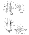
- Fig. 1 shown in Fig. 1 is an expansion bullet, generally identified with 10, comprising a hollow housing 11 (made of softer material, copper for example) with an open tip 12 and containing an element 13 (made of harder material, brass for example) in a chamber 15, which element is designed to slide backward upon the impact against a target.
- the stroke of the sliding element is limited by the starting distance between a step 22 and the bottom of chamber 15 in the housing.
- Element 13 has a head portion 14 the side surface of which slides within the axial chamber 15 formed in the hollow housing.
- a rear shank 16 Projecting backward from the head side 14 is a rear shank 16 passing through the housing bottom at an axial hole 17 so as to project from said bottom and widen out in the form of a washer 19 of substantially the same diameter as that of the housing bottom.
- This washer can be made of one piece construction or not with the end extremity of the shank. Consequently, head 14 can be made of one piece construction or not with shank 16 to enable easy mounting of the bullet.
- the head 14 can be screw-mounted or riveted on the shank after insertion of the shank from the outside through the hole at the bottom and within chamber 15.
- the washer can be screw-mounted or riveted on the rear end of the shank after insertion of the shank into the chamber to come out of the projectile bottom through hole 17.
- element 13 can be made of one piece construction with the washer (which must not necessarily be of the shape herein shown) formed by riveting of the shank 16 end after mounting of the element in the seat 15 and through hole 17.
- washer 19 is the bullet bottom supporting the impact in the shooting step and it can be made suitably hard, irrespective of the relative yielding feature that, on the contrary, must be supplied to housing 11 to enable opening of same.
- the washer can also have a smaller diameter than the bullet diameter and be embedded in a suitable seat 18 at the washer bottom.
- Housing 11 is made so as to open flowerwise under the thrust of material from the target entering the housing tip simultaneously with a backward movement of the sliding element 13.
- the housing in the tip region is provided with means facilitating separation of its side wall into petals.
- said facilitating means comprises relieves 21 distributed at intervals on the periphery of the inner wall of the chamber for receiving the sliding element and directed backward from the housing tip.
- the resisting means comprises an annular friction element 20 coaxially disposed between the sliding element and the housing.
- This element can be a suitably sized Seeger ring or an O-ring.
- Fig. 2 Diagrammatically shown in Fig. 2 is bullet 10 after the impact against the target, with the sliding element 13 withdrawn within the housing and the housing completely “flowerwise" open.
- Opening is caused by the soft material of the target that, exerting pressure on the head of the sliding element, causes a backward movement of the latter and penetrates into the cavity becoming gradually clear, so that it gets wedged and forces expansion of the petal extremities.
- the effect can be easily calibrated during manufacture of the bullet by suitably selecting the length and number of the relieves 21 to weaken areas of the housing wall to a more or less important degree, as well as selecting the stroke of element 13 in the chamber to adjust the amount of the target material entering the housing cavity.
- the bullet in accordance with the invention supplies excellent performance and a satisfactory amount of penetration. Shot tests in ballistic gelatine have shown suitably low penetration values. In addition, by modifying the above mentioned parameters the desired expansion and perforation values can be reached with ease.
- the bullet in the housing of a high-density target the bullet reduces its expansion, accordingly increasing its penetration capacity.
- the inner element is also used as a perforating element.
- the element shape can be modified and at the maximum point of its back movement, the element becomes integral with the outer portion practically forming a solid metal block.
Landscapes
- Engineering & Computer Science (AREA)
- Chemical & Material Sciences (AREA)
- Combustion & Propulsion (AREA)
- General Engineering & Computer Science (AREA)
- Aiming, Guidance, Guns With A Light Source, Armor, Camouflage, And Targets (AREA)
Abstract
Description
- Fig. 1 represents a view of a bullet in accordance with the invention, sectioned along line I-I in Fig. 2;
- Fig. 2 is a front view of the bullet in Fig. 1;
- Fig. 3 is a view similar to that in Fig. 1 and sectioned along line III-III in Fig. 4, of the bullet in Fig. 1 after an impact against a target;
- Fig. 4 is a front view of the bullet in Fig. 3.
Claims (7)
- An expansion bullet comprising a hollow housing (11) to internally define a chamber (15) with an open tip (12) and containing a slidable element (13) in the chamber (15) which is designed to slide backward in the chamber itself upon an impact against a target, the sliding element (13) comprising a tip portion (14) appearing at an opening (12) on the housing tip and an axial rear shank (16) that is received in a corresponding hole (17) at the rear bottom of the housing to be slidably guided in said backward stroke, the housing (11) being such made as to open flowerwise under the thrust of material from the target which enters the housing from the tip simultaneously with a back movement of said sliding element (13) in the chamber.
- A bullet as claimed in claim 1, characterised in that the housing (11) in the tip region has means (21) facilitating separation of its side wall into petals during the flowerwise opening.
- A bullet as claimed in claim 1, characterised in that the shank end (16) appears from said hole (17) at the rear bottom of the housing and widens in a radial direction in the form of a washer (19) to at least partly cover the outer bottom of the housing.
- A bullet as claimed in claim 3, characterised in that said washer (19) is received in a seat (18) formed at the outer bottom of the housing.
- A bullet as claimed in claim 1, characterised in that the separation-facilitating means comprises relieves (21) on the inner wall of the chamber (15) for receiving the slidable element and directed backward from the housing tip.
- A bullet as claimed in claim 1, characterised in that it comprises means (20) for resisting the free backward sliding of the sliding element.
- A bullet as claimed in claim 6, characterised in that the resisting means comprises an annular friction element (20) coaxially disposed between the sliding element and the housing.
Applications Claiming Priority (2)
| Application Number | Priority Date | Filing Date | Title |
|---|---|---|---|
| ITMI20021869 | 2002-08-30 | ||
| ITMI20021869 ITMI20021869A1 (en) | 2002-08-30 | 2002-08-30 | CONTROLLED EXPANSION BULLET. |
Publications (2)
| Publication Number | Publication Date |
|---|---|
| EP1394498A2 true EP1394498A2 (en) | 2004-03-03 |
| EP1394498A3 EP1394498A3 (en) | 2004-08-11 |
Family
ID=31198624
Family Applications (1)
| Application Number | Title | Priority Date | Filing Date |
|---|---|---|---|
| EP03017049A Withdrawn EP1394498A3 (en) | 2002-08-30 | 2003-07-28 | A controlled-expansion bullet |
Country Status (2)
| Country | Link |
|---|---|
| EP (1) | EP1394498A3 (en) |
| IT (1) | ITMI20021869A1 (en) |
Cited By (3)
| Publication number | Priority date | Publication date | Assignee | Title |
|---|---|---|---|---|
| FR2867267A1 (en) * | 2004-03-08 | 2005-09-09 | Jean Claude Sauvestre | Ammunition round for hunting gun has bullet with cylindrical ring forming open cavity on its tip to expand it on impact |
| FR2867266A1 (en) * | 2004-03-04 | 2005-09-09 | Jean Claude Sauvestre | Ammunition round with delayed expansion for hunting gun has inner bolt that projects from nose of bullet sliding into cavity on impact |
| WO2006096944A1 (en) * | 2005-03-17 | 2006-09-21 | Cbc Companhia Brasileira De Cartuchos | Expansion projectile for firearms |
Family Cites Families (8)
| Publication number | Priority date | Publication date | Assignee | Title |
|---|---|---|---|---|
| US44492A (en) * | 1864-09-27 | Tors op e | ||
| US854923A (en) * | 1907-04-01 | 1907-05-28 | George F Mcrae | Bullet. |
| US1493614A (en) * | 1920-09-01 | 1924-05-13 | Remington Arms Co Inc | Mushroom bullet |
| DE2541632A1 (en) * | 1975-09-18 | 1977-03-24 | Schirnecker Hans Ludwig Ing | Firearm cartridges which spread impact effects - to dissipate shock or chemicals via a splayed (plastic) body |
| US5149913A (en) * | 1990-09-05 | 1992-09-22 | Arakaki Steven Y | Forced expanding bullet |
| FR2671620A1 (en) * | 1991-01-10 | 1992-07-17 | Kaladgew Andre | Bullet with controlled expansion for a weapon with a smooth or rifled barrel |
| DE19711344C2 (en) * | 1997-03-18 | 1999-04-01 | Rudolf Koeppen | High-speed hollow cylinder bullet with integrated sabot for firearms |
| ES1044605Y (en) * | 1999-11-23 | 2000-09-16 | Garcia Juan Martinez | ROTARY AND EXPLOSIVE PROJECTILE BY COMPRESSED AIR. |
-
2002
- 2002-08-30 IT ITMI20021869 patent/ITMI20021869A1/en unknown
-
2003
- 2003-07-28 EP EP03017049A patent/EP1394498A3/en not_active Withdrawn
Cited By (5)
| Publication number | Priority date | Publication date | Assignee | Title |
|---|---|---|---|---|
| FR2867266A1 (en) * | 2004-03-04 | 2005-09-09 | Jean Claude Sauvestre | Ammunition round with delayed expansion for hunting gun has inner bolt that projects from nose of bullet sliding into cavity on impact |
| WO2005085745A3 (en) * | 2004-03-04 | 2005-11-10 | Jean-Claude Sauvestre | Delayed expansion hunting bullet |
| FR2867267A1 (en) * | 2004-03-08 | 2005-09-09 | Jean Claude Sauvestre | Ammunition round for hunting gun has bullet with cylindrical ring forming open cavity on its tip to expand it on impact |
| WO2005088234A3 (en) * | 2004-03-08 | 2005-11-10 | Jean-Claude Sauvestre | Hunting bullet comprising an expansion ring |
| WO2006096944A1 (en) * | 2005-03-17 | 2006-09-21 | Cbc Companhia Brasileira De Cartuchos | Expansion projectile for firearms |
Also Published As
| Publication number | Publication date |
|---|---|
| ITMI20021869A1 (en) | 2004-02-29 |
| EP1394498A3 (en) | 2004-08-11 |
Similar Documents
| Publication | Publication Date | Title |
|---|---|---|
| US6182574B1 (en) | Bullet | |
| EP2788711B1 (en) | A bullet | |
| US3881421A (en) | Bullet | |
| US5223667A (en) | Plural piece flechettes affording enhanced penetration | |
| US8511233B2 (en) | Projectile for fire arms | |
| JP4593045B2 (en) | Warhead with supported inner core | |
| US5127332A (en) | Hunting bullet with reduced environmental lead exposure | |
| US8087359B2 (en) | Hunting bullet comprising an expansion ring | |
| US9003974B2 (en) | Hollow-channel projectile nose and shaping of a projectile body in the nose region | |
| US8438767B2 (en) | Expanding projectile | |
| CA2408569C (en) | Small-calibre deformation projectile and method for the manufacture thereof | |
| BG62186B1 (en) | Bullet having entire metal casing and concave top end | |
| US5149913A (en) | Forced expanding bullet | |
| KR101660887B1 (en) | Bullet | |
| US1023469A (en) | Cartridge. | |
| RU2002130581A (en) | EQUIPMENT (OPTIONS) | |
| US20070028793A1 (en) | Hunting bullet with reduced aerodynamic resistance | |
| US20040003747A1 (en) | Method for expanding a bullet and a bullet | |
| US5979330A (en) | Integrated one-piece plastic shotshell wad | |
| GB2052693A (en) | A Pellet for an Air, Gas or Spring Gun | |
| US7451705B2 (en) | Non-discarding sabot projectile system | |
| RU2087843C1 (en) | Hunting cartridge bullet for rifled weapon (variants) | |
| GB2228211A (en) | No bounce dart | |
| US5133262A (en) | Penetrator | |
| GB2279440A (en) | Projectile for an air,gas or spring gun |
Legal Events
| Date | Code | Title | Description |
|---|---|---|---|
| PUAI | Public reference made under article 153(3) epc to a published international application that has entered the european phase |
Free format text: ORIGINAL CODE: 0009012 |
|
| AK | Designated contracting states |
Kind code of ref document: A2 Designated state(s): AT BE BG CH CY CZ DE DK EE ES FI FR GB GR HU IE IT LI LU MC NL PT RO SE SI SK TR |
|
| AX | Request for extension of the european patent |
Extension state: AL LT LV MK |
|
| PUAL | Search report despatched |
Free format text: ORIGINAL CODE: 0009013 |
|
| AK | Designated contracting states |
Kind code of ref document: A3 Designated state(s): AT BE BG CH CY CZ DE DK EE ES FI FR GB GR HU IE IT LI LU MC NL PT RO SE SI SK TR |
|
| AX | Request for extension of the european patent |
Extension state: AL LT LV MK |
|
| AKX | Designation fees paid | ||
| REG | Reference to a national code |
Ref country code: DE Ref legal event code: 8566 |
|
| STAA | Information on the status of an ep patent application or granted ep patent |
Free format text: STATUS: THE APPLICATION IS DEEMED TO BE WITHDRAWN |
|
| 18D | Application deemed to be withdrawn |
Effective date: 20050215 |