EP1397823B1 - Spectrometre de masse a temps de vol destine a la surveillance des processus rapides - Google Patents
Spectrometre de masse a temps de vol destine a la surveillance des processus rapides Download PDFInfo
- Publication number
- EP1397823B1 EP1397823B1 EP02731915A EP02731915A EP1397823B1 EP 1397823 B1 EP1397823 B1 EP 1397823B1 EP 02731915 A EP02731915 A EP 02731915A EP 02731915 A EP02731915 A EP 02731915A EP 1397823 B1 EP1397823 B1 EP 1397823B1
- Authority
- EP
- European Patent Office
- Prior art keywords
- ion
- time
- ions
- detector
- position sensitive
- Prior art date
- Legal status (The legal status is an assumption and is not a legal conclusion. Google has not performed a legal analysis and makes no representation as to the accuracy of the status listed.)
- Expired - Lifetime
Links
- 238000000034 method Methods 0.000 title claims abstract description 81
- 238000012544 monitoring process Methods 0.000 title abstract description 10
- 150000002500 ions Chemical class 0.000 claims description 285
- 238000000605 extraction Methods 0.000 claims description 73
- 230000037230 mobility Effects 0.000 claims description 60
- 230000004913 activation Effects 0.000 claims description 12
- 230000002123 temporal effect Effects 0.000 claims description 11
- 238000005259 measurement Methods 0.000 claims description 9
- 238000012545 processing Methods 0.000 claims description 7
- 230000003252 repetitive effect Effects 0.000 claims description 6
- 230000003213 activating effect Effects 0.000 claims description 5
- 238000004891 communication Methods 0.000 claims description 4
- 238000004458 analytical method Methods 0.000 description 12
- 238000002366 time-of-flight method Methods 0.000 description 10
- 230000004304 visual acuity Effects 0.000 description 10
- 238000001514 detection method Methods 0.000 description 7
- 238000010828 elution Methods 0.000 description 7
- 230000007935 neutral effect Effects 0.000 description 7
- 238000001228 spectrum Methods 0.000 description 6
- 230000008901 benefit Effects 0.000 description 5
- 239000002245 particle Substances 0.000 description 5
- 238000011084 recovery Methods 0.000 description 5
- 239000000126 substance Substances 0.000 description 5
- 230000001133 acceleration Effects 0.000 description 4
- 230000005684 electric field Effects 0.000 description 4
- 238000013467 fragmentation Methods 0.000 description 4
- 238000006062 fragmentation reaction Methods 0.000 description 4
- 238000004519 manufacturing process Methods 0.000 description 4
- 238000000926 separation method Methods 0.000 description 4
- 239000012491 analyte Substances 0.000 description 3
- 238000013480 data collection Methods 0.000 description 3
- 238000013461 design Methods 0.000 description 3
- 239000000284 extract Substances 0.000 description 3
- 230000035945 sensitivity Effects 0.000 description 3
- 238000001311 chemical methods and process Methods 0.000 description 2
- 230000001419 dependent effect Effects 0.000 description 2
- 238000011835 investigation Methods 0.000 description 2
- 230000005540 biological transmission Effects 0.000 description 1
- 230000015572 biosynthetic process Effects 0.000 description 1
- 238000006243 chemical reaction Methods 0.000 description 1
- 238000012937 correction Methods 0.000 description 1
- 230000003247 decreasing effect Effects 0.000 description 1
- 230000003111 delayed effect Effects 0.000 description 1
- 230000001627 detrimental effect Effects 0.000 description 1
- 238000011161 development Methods 0.000 description 1
- 238000010586 diagram Methods 0.000 description 1
- 238000010894 electron beam technology Methods 0.000 description 1
- 238000005516 engineering process Methods 0.000 description 1
- 238000005530 etching Methods 0.000 description 1
- 230000001747 exhibiting effect Effects 0.000 description 1
- 238000002474 experimental method Methods 0.000 description 1
- 238000007429 general method Methods 0.000 description 1
- 238000003384 imaging method Methods 0.000 description 1
- 230000000977 initiatory effect Effects 0.000 description 1
- 238000000951 ion mobility spectrometry-mass spectrometry Methods 0.000 description 1
- 238000010884 ion-beam technique Methods 0.000 description 1
- 238000004949 mass spectrometry Methods 0.000 description 1
- 238000001819 mass spectrum Methods 0.000 description 1
- 238000001451 molecular beam epitaxy Methods 0.000 description 1
- 238000000329 molecular dynamics simulation Methods 0.000 description 1
- 230000035515 penetration Effects 0.000 description 1
- 238000001020 plasma etching Methods 0.000 description 1
- 239000004065 semiconductor Substances 0.000 description 1
- 238000011896 sensitive detection Methods 0.000 description 1
- 238000000992 sputter etching Methods 0.000 description 1
- 230000001550 time effect Effects 0.000 description 1
- 238000001269 time-of-flight mass spectrometry Methods 0.000 description 1
Images


Classifications
-
- H—ELECTRICITY
- H01—ELECTRIC ELEMENTS
- H01J—ELECTRIC DISCHARGE TUBES OR DISCHARGE LAMPS
- H01J49/00—Particle spectrometers or separator tubes
- H01J49/02—Details
- H01J49/025—Detectors specially adapted to particle spectrometers
-
- H—ELECTRICITY
- H01—ELECTRIC ELEMENTS
- H01J—ELECTRIC DISCHARGE TUBES OR DISCHARGE LAMPS
- H01J49/00—Particle spectrometers or separator tubes
- H01J49/0027—Methods for using particle spectrometers
- H01J49/0031—Step by step routines describing the use of the apparatus
-
- H—ELECTRICITY
- H01—ELECTRIC ELEMENTS
- H01J—ELECTRIC DISCHARGE TUBES OR DISCHARGE LAMPS
- H01J49/00—Particle spectrometers or separator tubes
- H01J49/004—Combinations of spectrometers, tandem spectrometers, e.g. MS/MS, MSn
-
- H—ELECTRICITY
- H01—ELECTRIC ELEMENTS
- H01J—ELECTRIC DISCHARGE TUBES OR DISCHARGE LAMPS
- H01J49/00—Particle spectrometers or separator tubes
- H01J49/26—Mass spectrometers or separator tubes
- H01J49/34—Dynamic spectrometers
- H01J49/40—Time-of-flight spectrometers
Definitions
- the invention is a time-of-flight mass spectrometer (TOF) capable of monitoring fast processes. More particularly, it is a TOF for monitoring the elution from an ion mobility spectrometer (IMS) operated at pressures between a few Torr and atmospheric pressure.
- TOF time-of-flight mass spectrometer
- IMS ion mobility spectrometer
- This apparatus is an instrument for qualitative and/or quantitative chemical and biological analysis.
- WO 00/70335 discloses an ion mobility and mass spectrometer instrument that includes an ion source region coupled to an ion mobility spectrometer having an ion outlet coupled to a quadrupole mass filter. An output of the filter is coupled to a collision cell which has an ion outlet coupled to an ion acceleration region of a mass spectrometer such as a time-of-flight mass spectrometer.
- the TOF serves as a mass monitor scanning the elution of the analyte of the prior separation methods.
- a third such example is the time evolution of ions either directly desorbed from a surface by energetic beams of X-ray, laser photons, electrons, or ions.
- the ions are desorbed from a surface there is usually a more predominant codesorption of non-ionized neutral elements and molecules whose time evolution can be monitored by first post ionizing neutral species which have been desorbed and then measuring mass separated time evolution of the ions by mass spectrometry.
- Yet a fourth area of use is the monitoring of the time evolution of neutral elements or molecules reflected after a molecular beam is impinged on a surface. The importance of such studies range from fundamental studies of molecular dynamics at surfaces to the practical application of molecular beam epitaxy to grow single crystalline semiconductor devices. A further application for fast analysis is presented by Fockenberg et al.
- TOF instruments typically operate in a semi-continuous repetitive mode.
- ions are first generated and extracted from an ion source (which can be either continuous or pulsed) and then focused into a parallel beam of ions.
- This parallel beam is then injected into an extractor section comprising a parallel plate and grid.
- the ions are allowed to drift into this extractor section for some length of time, typically 5 ⁇ s.
- the ions in the extractor section are then extracted by a high voltage pulse into a drift section followed by reflection by an ion mirror, after which the ions spend additional time in the drift region on their flight to a detector.
- the time-of-flight of the ions from extraction to detection is recorded and used to identify their mass.
- Typical times-of flight of the largest ions of interest are in the range of 20 ⁇ s to 200 ⁇ s.
- the extraction frequencies are usually in the range of 5 kHz to 50 kHz. If an extraction frequency of 50 kHz is used, the TOF is acquiring a full mass spectrum every 20 ⁇ s.
- This so-called fill up time is typically relatively shorter for lighter ions as compared to heavier ions because they travel faster in the primary beam.
- the fill up time may be as short as 1 ⁇ s whereas for very large ions, the fill up time may exceed the 20 ⁇ s between each extraction, and hence those large ions never completely fill up the extraction region.
- the fill up time depends on the ion energy in the primary beam, the length of the extraction region and the mass of the ions.
- Some fast processes require monitoring with a time resolution in the microsecond range.
- a species eluting from an ion mobility spectrometer may elute through the orifice within a time interval of 15 ⁇ s. If this species also has a small fill up time it is possible that this elution occurs between two TOF extractions in such a way that the TOF completely misses the eluting species.
- the ion flight time in the TOF section will determine the maximum extraction frequency, shorter flight times yielding higher extraction rates.
- the ion flight time is shortened by either increasing the ion energy in the drift section, or by reducing the length of the drift section.
- Increasing the ion energy is the preferred method, because decreasing the drift length results in a loss of resolving power.
- T a E
- An apparatus according to the present invention comprises the features defined in claim 1.
- the predetermined sequence includes a time offset between the activation of the ion source and the activation of the ion extractor.
- This time offset may be variable. Typical time offset ranges from 0 to 1000 ⁇ s.
- the apparatus has a position sensitive ion detector having a meander delay line.
- the detector may have multiple meander delay lines.
- the position sensitive ion detector may have multiple anodes.
- the multiple anode detector may have anodes of different size.
- the steps of generating and activating extraction include a time offset between them.
- the time offset may be varied. Typical time offset ranges are from 0 to 1000 ⁇ s.
- the kinetic energy of the ions is adjusted before the step of extracting.
- the position sensitive ion detector may be a meander delay line detector.
- the position sensitive ion detector may have multiple meander delay lines.
- the position sensitive ion detector may comprise multiple anodes. In a specific multiple anode embodiment, the detector may have one or more anodes of different size.
- FIG. 1 Mobility-TOF comprising the basic architecture of the present invention.
- the interleaved timing scheme is used with this instrumental platform.
- FIG. 2 Illustrative timing scheme of the interleaved TOF acquisition.
- FIG. 3 A more detailed illustration of the timing scheme of the interleaved TOF acquisition.
- FIG. 4 Embodiment incorporating a delay-line position sensitive detector to the basic Mobility-TOF of Figure 1 in order to distinguish ions arriving early to the ion extractor from those arriving at later times.
- FIG. 5 Embodiment incorporating a multi-anode position sensitive detector to the basic Mobility-TOF of Figure 1 in order to distinguish ions arriving early to the ion extractor from those arriving at later times.
- Figure 6 Figure illustrating various ion transmission times and distances used in the governing equations in the Mobility-TOF of the invention.
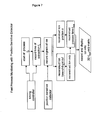
- Figure 7 Flow diagram illustrating the scheme for the reconstruction of the process time of an ion from the extraction time, and the ion m/z.
- a or “an” may mean one or more.
- the words “a” or “an” when used in conjunction with the word “comprising”, the words “a” or “an” may mean one or more than one.
- another may mean at least a second or more.
- fluidly coupled refers to the relationship wherein two components are linked, i.e., as where the output of one of the components is input for the other component.
- linkage may be a physical connection, this is not essential. For example, assuming two components (A and B), if the output of component A becomes (either immediately or at some later point) input for component B, or alternatively, if the output of component B becomes (either immediately or at some later point) input for component A, then components A and B are "fluidly coupled".
- One example of such output may be the mobility-separated ions exiting an ion mobility cell, while an example of such input may be the mobility-separated ions entering a time-of-flight mass spectrometer.
- Interleaved timing sequence is defined as a timing sequence that controls an interleaved data acquisition.
- Interleaved data acquisition refers to a method where the data points of a time series are reconstructed from measurements of several passes through the series. For example, the odd data points of a time series may be acquired in the first pass (i.e. data points 1,3,5,7,...) and the even data points are acquired in the second pass (data points 2,4,6,8,).
- the essence of the interleaved method is the time offset between ion generation and ion extraction. The different data time points are collected through the use of such a time offset. Interleaved timing is therefore synonymous with a time offset between ion generation and extraction.
- the time offset Figure 2 illustrates an interleaved timing sequence where the time series is composed from acquisitions from 8 passes.
- the actual times in any analysis may vary from the illustrated values in the figure.
- the range of times can be large and generally vary from 0 to 1000 ⁇ s.
- IMS is defined as an ion mobility spectrometer.
- An ion mobility spectrometer is consists of a drift tube in which ions traveling in a gaseous medium in the presence of an electric field are separated according to their ion mobilities. The ion mobilities of specific ion species are result from the conditions of drift tube pressure and potential of the ion mobility experiment. The repetitive accelerations in the electric field and collisions at the molecular level result in unique ion mobilities for different ion species.
- IMS/MS is a combination of an ion mobility spectrometer and a mass spectrometer.
- a mass spectrometer separates and analyzes ions under the influence of a potential according to their mass to charge ratios.
- IMS/IFP/MS is a combination of an ion mobility spectrometer and a mass spectrometer with an ion fragmentation process between them.
- the ion fragmentation process can be any of those commonly known in the mass spectrometric art.
- position sensitive ion detector As used herein, "position sensitive ion detector”, or PSD, is defined as an ion detector having the ability to detect the location of the analyte species within the detector at the time of detection. This is contrasted to detectors in which only the presence but not the location of the analyte within the detector is detected.
- position sensitive ion detector is synonymous with “position sensitive detection means” and “position sensitive detector” and may include, but is not limited to, meander delay line detectors, multiple meander delay line detectors, and multi-anode detectors in which the individual anodes may be of the same or different sizes.
- time resolving power is defined as the time of ion release by a process and the accuracy with which this release time can be determined. This is expressed mathematically as T/ ⁇ T where T is the time of ion release in the process and ⁇ T is the accuracy of the measurement of T. It is used synonymously with “temporal resolving power”.
- TOF is defined as a time-of-flight mass spectrometer.
- a TOF is a type of mass spectrometer in which ions are all accelerated to the same kinetic energy into a field-free region wherein the ions acquire a velocity characteristic of their mass-to-charge ratios. Ions of differing velocities separate and are detected.
- the temporal development of the ion generation itself is analyzed. For example, the kinetics of the formation of a chemical ion species during a discharge may be investigated. In other cases, a chemical or physical process that does not generate ions but only neutral particles may be under investigation. In this case these neutral particles will have to be ionized for the analysis. The analysis of neutral species in a chemical reaction is an example for such an application. In still another case, the temporal release of existing ions may be of interest.
- FIG. 2 is the specific case wherein a mobility spectrometer (2) is used as the source of such an ion process.
- Some ion mobility spectrometers separate ions on a very short time scale; i.e., just a few microseconds. Hence, to identify the ions eluting from the ion mobility spectrometer, the TOF has to detect those ions and resolve their mobility drift time.
- the ions eluting from the IMS are accelerated immediately into a primary beam (4) of an energy of 20 to 200 eV in order to minimize the time to travel from the IMS exit orifice (24) to the TOF extraction chamber (31). The ions then pass through the extraction chamber.
- the timing controller (60) issues an ion extraction, the ion will be mass analyzed and its mobility drift time is identified with the time at which the extraction occurs.
- the interleaved timing scheme allows the scanning of the ions in the primary beam (4).
- An ion species that passed through the extractor without being extracted and detected in one mobility spectrum will be detected in a following mobility spectrum. This is accomplished by varying the time offset between the start of the mobility process at (1) and the TOF extraction sequence at (31), as illustrated in Figure 2 .
- the ion extractor i.e., the extraction chamber
- an orthogonal extractor is illustrated.
- An orthogonal extractor extracts the ions in orthogonal direction to their initial flight direction in the primary ion beam (4).
- Other types of TOF function with a coaxial extraction.
- the interleaved method works with both orthogonal and coaxial extractors.
- the ion extractor of Figure 1 uses a double pulsed extractor.
- the back plate of the extraction chamber as well as the second grid are pulsed by a high voltage pulser (61).
- only one electrode is pulsed, e.g. only the back plate or only the first grid.
- the ions are not extracted by a pulsed electric field, but by a fast creation of the ions within the extractor (31).
- the electric field is always present, and the particles enter the extraction region (31) as neutrals.
- a pulsed ionizing beam e.g. an electron beam or a laser beam, is then used to simultaneously create and extract the ions.
- the extracting field is slightly delayed with respect to the ion generation step in order to improve the time focussing properties of the TOF instrument.
- the ion detector is used to create the stop signal of the time-of-flight measurement.
- the most common detectors used in TOF are electron multiplier detectors, where the ion to be detected generates one or several electrons by collision with an active surface. An acceleration and secondary electron production process then multiplies each electron. This electron multiplication cycle is repeated several times until the resulting electron current is large enough to be detected by conventional electronics.
- Some more exotic detectors detect the ion energy deposited in a surface when the ion impinges on the detector.
- Some other detectors make use of the signal electrically induced by the ion in an electrode. Any and all of these apparatuses and corresponding methods of ion detection, which are discussed in detail in the literature and known to those of ordinary skill in the art, are collectively referred to as "ion detector”.
- the first method includes an interleaved timing scheme and the second method uses a position sensitive detector. Both of these methods allow one to obtain temporal information of the fast ion processes.
- the interleaved timing scheme is illustrated in Figures 2 and 3 and may be used with the instrumental platform shown in Figure 1 .
- the critical variable is the pulsing scheme that is generated by the timing controller (60).
- the interleaved timing scheme is applicable to mass analysis of any repetitive process.
- Figure 1 shows the ion output of a mobility spectrometer (2) is such a process.
- the pressures in the ion mobility region (2) are typically a few hundred Pascal (a few Torr) to approximately atmospheric pressures.
- Some ion mobility spectrometers separate ions on a very short time scale i.e., less than 100 ⁇ s.
- the TOF has to detect those ions and resolve their mobility drift time.
- the ions eluting from the IMS through an orifice (24) are accelerated immediately into a primary beam (4) to a energy of 20 to 200 eV in order to minimize the time to travel from the IMS exit orifice (24) to the TOF extraction chamber (31).
- the pressure in region (4) is typically on the order of 0,0133 Pa (10 -4 Torr)
- the ions then enter the extraction chamber (31).
- the timing controller (60) issues an ion extraction, the ions will be mass analyzed in flight tube (33) and their mobility drift time is identified with the time at which the extraction occurred.
- the pressures in the flight tube region are typically on the oder of 1,33.10 -4 Pa (10 -6 Torr).
- the interleaved timing scheme allows scanning the primary beam ion arrival times in the extraction chamber (31) relative to the time they were generated in the ion source (1). Ion species that pass through the extractor without being extracted and detected in one mobility spectrum will be detected in a following mobility spectrum. This is accomplished by variation of the time offset between the start of the mobility process (1) and the TOF extraction sequence, as illustrated in Figure 2 and Figure 3 .
- Figure 2 illustrates how the offset between the ion production (by laser) and the ion extraction sequence is increased by 5 ⁇ s (the interleaved time) for each ion production cycle.
- Figure 3 illustrates the same sequence in greater detail.
- the time delay until the first ion exits the mobility chamber is also indicated, as well as a laser recovery time, e.g., the time between the end of the mobility spectrum and the time at which a new laser pulse can be issued.
- the laser recovery time is largely time lost during the delay for the laser to recover for a new ion production cycle.
- the laser recovery time is variable.
- times shown in the figures are illustrative and a number of lasers exhibiting a wide range of recovery times may be used.
- the range of offset times extends from zero to the time between two extractions. This is illustrated schematically in Figure 2 .
- the extraction frequency is maximized in order to maximize data collection. However, this is limited by the mass and energy of the ions of interest and the instrumental flight path length.
- the offset range is automatically determined, ranging from 0 to the time corresponding to one extraction cycle.
- Data collection is then modified by choosing a different step size of the offset (interleaved time) within the offset range. In order to insure that no part of the time profile of the process under study goes unmonitored, this step size cannot larger than the maximum offset range. The smaller the step size, the greater the temporal resolution of the data, however, this comes at the expense of longer data collection times.
- the extraction frequency is 10 kHz
- the time between two extractions is 100 ⁇ s.
- the step size will be 20 ⁇ s.
- the offset pattern will be 0, 20, 40, 60, 80, 100 ⁇ s.
- An offset range of 0 to 1000 ⁇ s is expected to cover most ion processes, corresponding to extraction frequencies down to 1 kHz.
- the smallest mobility drift time differences that can be detected with this method corresponds to the "filling time" of the extraction chamber (31).
- This filling time is the time it takes an ion species to pass through the open extraction area.
- the differential filling time effect on ions entering the ion extractor at different times is illustrated in Figure 4 .
- An ion with a short mobility drift time will enter the extraction chamber early and at the time of extraction it will have moved in the extraction chamber to an extraction position (5).
- Another ion with a slightly longer mobility time will enter the extraction chamber later and at the moment of extraction it may be at a different position (6).
- the mobility drift time of those two ions cannot be distinguished easily with instruments of the prior art; applying an interleaved timing mode helps to alleviate this problem.
- the instruments shown in Figures 4 and 5 include position sensitive ion detectors (42) and (43), respectively, which allow one to distinguish between the ion extracted at a first position (5) and the ion extracted at a second position (6).
- the ability to distinguish these ions is based upon the different locations at which these ions impinge upon the detector. These different locations are schematically shown as (5a) and (6a), respectively.
- the use of the position sensitive ion detector (42) and (43) in Figures 4 and 5 respectively, improves the time resolution to less than the extraction fill time.
- the detector (43) of Figure 5 is a multi-anode detector with limited position resolving capabilities but high count rate capabilities.
- Detector (42) of Figure 4 is a meander delay line based position sensitive ion detector (see US 5,644,128 of Wollnik ) with high position resolving power in at least one dimension, but with limited count rate capability.
- the preferred embodiment of the present invention would utilize a combination of these two detectors by using several delay line anodes (multiple meander delay lines) in order to obtain. good position resolving power and high count rate capability.
- the PSD In order to exploit the PSD fast acquisition method; the PSD requires a good position resolving capability in this first 1/5th of the detector (at position 6a). At the other end of the PSD (around position 5a), poorer position resolving capability may not be as detrimental to overall performance.
- Figure 6 and the following mathematical treatment illustrates how the present invention allows one to reconstruct the mobility drift time t mob from the time of extraction t x .
- the ion passes through the extraction chamber (31) for a certain time t d until at time t x an extraction occurs. At that time, the ion is at position (5), which is the length s further inside the beginning (6) of the open area in the extraction chamber (31). This position is monitored with the position sensitive ion detector (43).
- E is the kinetic energy of the particle in question and U is the acceleration voltage which gave the particle the energy, E.
- the parameters a, b, c and d are instrumental parameters that depend on the TOF geometry and the potentials applied. Once those parameters are known, the mobility time t mob can be calculated with the m / z information from the time-of-flight measurement and the distance s information from position sensitive ion detector with the process indicated in Figure 7 . For each ion, the process time, t mob , which is the time of interest, can be calculated with the process start time t 0 , the extraction time t x , the ion position s , and the ion m / z by applying equations (1) to (4).
- Figure 7 also illustrates how t 0 and t x are determined using the corresponding signals from the timing controller, whereas the position information s and the ion time-of-flight tof (eqn . 4) are derived from signals produced by the PSD.
- the parameters a and b are instrumental parameters that depend on the TOF geometry and the potentials applied. Once those parameters are known, the mobility time t mob can be calculated with the m / z information from the time-of-flight measurement and the distance s information from position sensitive detector as indicated in Figure 7 .
- This treatment is applicable not only for IMS-TOF combinations, but for the monitoring of any fast processes.
- the transit time, t p is reduced by reducing the distance between the mobility cell exit (24) and the beginning of the open extractor area (6), and by accelerating the ions within this region.
- the differences in the transit time t p may become insignificant and the parameter b may remain unknown.
- t mob instead of determining the mobility time, t mob it is often sufficient to determine the time t mob + t p .
- Equation (3) also indicates that for ions with large m / z , the penetration into the extraction chamber is slow. Many of the larger ions will experience extraction early upon entry into the extraction chamber. A multi-anode detector configuration is helpful in improving position resolving power. Further, when using a multi-anode position sensitive detector (43), it is desirable to have smaller anodes in the area (6a) in order to increase the position resolving power for large m / z ions impinging in this area. This will maintain a process time resolving power for those large m / z ions.
- One skilled in the art recognizes that larger m / z ions will travel slowly from position (6) to position (5) than would smaller m / z ions. Potentially, these slower traveling ions may never reach position (5) because a new extraction event will occur before this time.
- IMS/IFP/MS is the tandem method where ions are fragmented after the mobility separation, e.g. in region (25), prior to the TOF extraction.
- This fragmentation may be induced by gas collisions, by collisions with surfaces, or by bombardment with fragmenting beams i.e., an electron or photon beam.
- fragmenting beams i.e., an electron or photon beam.
- the correlation between mobility and mass is lost due to the fragmentation process creating light ions from ions with low mobility.
- One example of a TOF instrument with PSD detection is as follows.
- An ion source repetitively generates ions. Ions from the ion source enter an ion extractor which extracts ions for time-of-flight measurement in a time-of-flight mass section.
- the ion extractor is fluidly coupled to the ion source.
- a position sensitive ion detector is fluidly coupled to the time-of-flight mass section to detect the ions issuing from it.
- a timing controller is in electronic communication with the ion source and the ion extractor and tracks and controls the time of activation of the ion source and activates the ion extractor according to a predetermined sequence.
- a data processing unit for analyzing and presenting data said data processing unit is in electronic communication with the ion source, the ion extractor, and the detector.
- the TOF/PSD instrument can be modified to incorporate an interleaved timing scheme to produce a interleaved TOF/PSD instrument. This is accomplished by including a time offset between the activation of the ion source and the activation of the ion extractor.
- the time offset may be variable. Typical time offset ranges are from 0 to 1000 ⁇ s.
- the interleaved/PSD combination would yield instruments and methods having the advantages of both technologies.
- the position sensitive ion detection method can be used in any TOF design with spatial imaging properties, e.g. a linear TOF design or in a TOF design with multiple reflections.
- the instrument of the previous paragraph could be modified to replace the PSD with an ion detector lacking position sensitivity.
- the result would be an interleaved-TOF instrument. While lacking the benefits of the PSD, such an instrument may be acceptable for analyses involving ions having a narrow spread of generation times.
- the TOF/PSD instrument can possess a number of different features and variations.
- the PSD may be based upon the meander delay line technique.
- Such a meander delay line detector may have multiple meander delay lines.
- the position sensitive ion detector may have also multiple anodes. If a multiple anode detector is used, it may have anodes of the same or differing sizes.
- Analytical methods can be based on the TOF/PSD instrument to determine the temporal profile of fast ion processes. This is accomplished by generating ions in an ion source, tracking the time of ion generation by a timing controller, and activating the extraction of the ions in a single or repetitive manner according to a predetermined sequence. The extracted ions are then separated in a time-of-flight mass spectrometer and detected with a position sensitive ion detector capable of resolving the location of impact of the ions onto the detector. The ions are then analyzed to determine the time characteristics of the fast ion processes from the ion impact location information, the time from the step of tracking, and the time of activation of the extractor. The temporal profile of the fast ion processes is thus determined.
- the steps of generating and activating extraction include a time offset between them.
- the time offset may be varied. Typical time offset ranges are from 0 to 1000 ⁇ s.
- the method of the previous paragraph could be modified to replace the PSD with an ion detector lacking position sensitivity.
- the result would be an interleaved-TOF method. While lacking the benefits of analogous methodology employing a PSD, these methods may be acceptable for analyses involving ions having a narrow spread of generation times.
- the kinetic energy of the ions is adjusted before the ion extraction.
- the position sensitive ion detector may be a meander delay line detector. It may have multiple meander delay lines.
- the position sensitive ion detector may comprise multiple anodes, wherein the multiple anodes may be of the same or different sizes.
- each instrument and method can be applied to any fast separation process, not being limited to IMS and can be used with ADC (analog-to-digital converter) or TDC (time-to-digital converter) detection schemes.
- ADC analog-to-digital converter
- TDC time-to-digital converter
Landscapes
- Chemical & Material Sciences (AREA)
- Analytical Chemistry (AREA)
- Other Investigation Or Analysis Of Materials By Electrical Means (AREA)
- Electron Tubes For Measurement (AREA)
- Sampling And Sample Adjustment (AREA)
Claims (18)
- Appareil comprenant :une source d'ions pour produire des ions de manière répétitive ;un spectromètre à mobilité ionique (2) conçu pour séparer lesdits ions selon leurs mobilités ioniquesun extracteur d'ions (31), couplé par fluide audit spectromètre à mobilité ionique (2) et conçu pour extraire lesdites ions pour la mesure de temps de vol ;une section de masse à temps de vol couplée par fluide audit extracteur d'ions et conçue pour accepter des ions en provenance de ce dernier ; etune unité de commande de chronométrage (60) en communication électronique avec ladite source d'ions et ledit extracteur d'ions (31), ladite unité de commande de chronométrage (60) étant conçue pour suivre et commander le temps d'activation de ladite source d'ions et pour activer ledit extracteur d'ions selon une séquence prédéterminée ;caractérisé parun détecteur d'ions sensible à la position (42, 43) couplé par fluide à ladite section de masse à temps de vol pour détecter lesdits ions ;dans lequel ledit détecteur (42, 43) est conçu pour détecter l'emplacement d'impact des ions sur le détecteur (42, 43) ;une unité de traitement de données pour analyser et présenter des données, ladite unité de traitement de données étant en communication électronique avec ladite source d'ions, ledit extracteur d'ions, et ledit détecteur d'ions sensible à la position (42, 43) ;dans lequel ladite unité de traitement de données est conçue pour déterminer le temps de glissement de mobilité ionique desdits ions à partir de l'emplacement d'impact des ions sur le détecteur (42, 43), le temps d'activation de la source d'ions, et le temps d'activation dudit extracteur.
- Appareil selon la revendication 1 dans lequel ladite séquence prédéterminée inclut un décalage temporel entre l'activation de ladite source d'ions et l'activation dudit extracteur d'ions (31).
- Appareil selon la revendication 2, dans lequel le décalage temporel est variable.
- Appareil selon la revendication 2, dans lequel ledit décalage temporel est compris entre 0 et 1 000 ps.
- Appareil selon la revendication 1, incluant en outre un moyen d'ajustement pour ajuster les énergies cinétiques desdits ions entrant dans ledit extracteur (31) selon leur masse.
- Appareil selon la revendication 1, dans lequel ledit détecteur d'ions sensible à la position (42) comprend une ligne de retard à méandres.
- Appareil selon la revendication 1, dans lequel ledit détecteur d'ions sensible à la position (42) possède de multiples lignes de retard à méandres.
- Appareil selon la revendication 1, dans lequel ledit détecteur d'ions sensible à la position (43) possède de multiples anodes.
- Appareil selon la revendication 8, dans lequel lesdites multiples anodes comprennent une ou plusieurs anodes de taille différente.
- Procédé de détermination du profil temporel de processus à ions rapides comprenant :la production d'ions dans une source d'ions ;la séparation desdits ions selon leurs mobilités ioniques dans un spectromètre à mobilité ionique (2) ;le suivi du temps de ladite étape de production par une unité de commande de chronométrage ;l'activation de l'extraction desdits ions d'une façon simple ou répétitive selon une séquence prédéterminée ; etla séparation desdits ions extraits dans un spectromètre de masse à temps de vol ;caractérisé parla détection desdits ions avec un détecteur d'ions sensible à la position (42, 43) susceptible de résoudre l'emplacement d'impact dudit ion sur ledit détecteur (42, 43) ;la détermination du temps de glissement de mobilité ionique desdits ionsà partir dudit emplacement d'impact d'ion, du temps à partir de l'étape de suivi, et du temps d'activation dudit extracteur (31).
- Procédé selon la revendication 10, dans lequel les étapes de production et d'activation de l'extraction incluent un décalage temporel entre elles.
- Procédé selon la revendication 11, dans lequel ledit décalage temporel est variable.
- Procédé selon la revendication 11, dans lequel ledit décalage temporel est compris entre 0 et 1 000 ps.
- Procédé selon la revendication 10, comprenant en outre l'étape d'ajustement de l'énergie cinétique des ions avant ladite étape d'extraction.
- Procédé selon la revendication 10, dans lequel ledit détecteur d'ions sensible à la position (42) comprend une ligne de retard à méandres.
- Procédé selon la revendication 10, dans lequel ledit détecteur d'ions sensible à la position (42) comprend de multiples lignes de retard à méandres.
- Procédé selon la revendication 10, dans lequel ledit détecteur d'ions sensible à la position (43) comprend de multiples anodes.
- Procédé selon la revendication 17, dans lequel ledit détecteur d'ions sensible à la position (43) comprend une ou plusieurs anodes de taille différente.
Applications Claiming Priority (3)
| Application Number | Priority Date | Filing Date | Title |
|---|---|---|---|
| US29373701P | 2001-05-25 | 2001-05-25 | |
| US293737P | 2001-05-25 | ||
| PCT/US2002/016341 WO2002097383A2 (fr) | 2001-05-25 | 2002-05-24 | Spectrometre de masse a temps de vol destine a la surveillance des processus rapides |
Publications (3)
| Publication Number | Publication Date |
|---|---|
| EP1397823A2 EP1397823A2 (fr) | 2004-03-17 |
| EP1397823A4 EP1397823A4 (fr) | 2007-05-23 |
| EP1397823B1 true EP1397823B1 (fr) | 2011-03-30 |
Family
ID=23130361
Family Applications (1)
| Application Number | Title | Priority Date | Filing Date |
|---|---|---|---|
| EP02731915A Expired - Lifetime EP1397823B1 (fr) | 2001-05-25 | 2002-05-24 | Spectrometre de masse a temps de vol destine a la surveillance des processus rapides |
Country Status (7)
| Country | Link |
|---|---|
| US (1) | US6683299B2 (fr) |
| EP (1) | EP1397823B1 (fr) |
| AT (1) | ATE504077T1 (fr) |
| AU (1) | AU2002303853A1 (fr) |
| CA (1) | CA2448990C (fr) |
| DE (1) | DE60239607D1 (fr) |
| WO (1) | WO2002097383A2 (fr) |
Cited By (1)
| Publication number | Priority date | Publication date | Assignee | Title |
|---|---|---|---|---|
| CN104472481A (zh) * | 2009-04-28 | 2015-04-01 | 贝多基安研究股份有限公司 | 臭虫的控制和驱除 |
Families Citing this family (45)
| Publication number | Priority date | Publication date | Assignee | Title |
|---|---|---|---|---|
| US7084395B2 (en) * | 2001-05-25 | 2006-08-01 | Ionwerks, Inc. | Time-of-flight mass spectrometer for monitoring of fast processes |
| EP1397821A2 (fr) * | 2001-06-08 | 2004-03-17 | University of Maine | Instrument de spectroscopie faisant intervenir une modulation a large bande et une estimation statistique |
| US6797943B2 (en) * | 2002-05-07 | 2004-09-28 | Siemens Ag | Method and apparatus for ion mobility spectrometry |
| CA2507491C (fr) * | 2002-11-27 | 2011-03-29 | Katrin Fuhrer | Spectrometre de masse a temps de vol dote d'un systeme d'acquisition des donnees perfectionne |
| EP1648595B1 (fr) * | 2003-06-06 | 2016-05-04 | Ionwerks | Implantation ou depot d'or dans des echantillons biologiques destines au profilage tridimensionnel en epaisseur de tissus par desorption laser |
| WO2004109254A2 (fr) | 2003-06-06 | 2004-12-16 | Ionwerks | Matrices maldi a base de fullerene pour peptides et proteines |
| DE10335718B4 (de) * | 2003-08-05 | 2007-05-03 | Johannes-Gutenberg-Universität Mainz | Anodenbauteil für Delayline-Detektoren und Delayline-Detektor |
| EP1700327A4 (fr) * | 2003-12-31 | 2010-05-05 | Ionwerks Inc | Spectrometrie de masse maldi par tof orthogonal/mobilite ionique a detection simultanee de mode positif et negatif |
| US20050269508A1 (en) * | 2004-06-03 | 2005-12-08 | Lippa Timothy P | Apparatus and methods for detecting compounds using mass spectra |
| US20100090101A1 (en) * | 2004-06-04 | 2010-04-15 | Ionwerks, Inc. | Gold implantation/deposition of biological samples for laser desorption two and three dimensional depth profiling of biological tissues |
| US20070187591A1 (en) * | 2004-06-10 | 2007-08-16 | Leslie Bromberg | Plasma ion mobility spectrometer |
| EP1789987A4 (fr) * | 2004-07-27 | 2010-09-29 | Ionwerks Inc | Modes d'acquisition de donnees de multiplexage pour une spectrometrie de masse de la mobilite des ions |
| GB0420408D0 (en) * | 2004-09-14 | 2004-10-20 | Micromass Ltd | Mass spectrometer |
| US7388193B2 (en) * | 2005-06-22 | 2008-06-17 | Agilent Technologies, Inc. | Time-of-flight spectrometer with orthogonal pulsed ion detection |
| JP5233670B2 (ja) * | 2005-11-16 | 2013-07-10 | 株式会社島津製作所 | 質量分析装置 |
| US9024255B2 (en) * | 2007-07-11 | 2015-05-05 | Excellims Corporation | Intelligently controlled spectrometer methods and apparatus |
| GB0624993D0 (en) * | 2006-12-14 | 2007-01-24 | Micromass Ltd | Mass spectrometer |
| JP5175859B2 (ja) * | 2006-12-14 | 2013-04-03 | マイクロマス ユーケー リミテッド | 質量分析計 |
| WO2010030718A2 (fr) * | 2008-09-11 | 2010-03-18 | Varian Semiconductor Equipment Associates, Inc. | Technique pour la surveillance et la commande d’un traitement par plasma à l’aide d’un spectromètre de mobilité ionique |
| RU2393579C1 (ru) * | 2009-08-17 | 2010-06-27 | Общество с ограниченной ответственностью "Лаборатория инновационных аналитических технологий" | Масс-спектрометр |
| US8633436B2 (en) | 2011-12-22 | 2014-01-21 | Agilent Technologies, Inc. | Data acquisition modes for ion mobility time-of-flight mass spectrometry |
| CN104508792B (zh) * | 2012-06-18 | 2017-01-18 | 莱克公司 | 使用非均匀采样的串联式飞行时间质谱法 |
| GB201304039D0 (en) * | 2013-03-06 | 2013-04-17 | Micromass Ltd | Time shift improved IMS digitisation |
| US9552970B2 (en) | 2013-03-06 | 2017-01-24 | Micromass Uk Limited | Time shift for improved ion mobility spectrometry or separation digitisation |
| US9627190B2 (en) * | 2015-03-27 | 2017-04-18 | Agilent Technologies, Inc. | Energy resolved time-of-flight mass spectrometry |
| GB201519830D0 (en) * | 2015-11-10 | 2015-12-23 | Micromass Ltd | A method of transmitting ions through an aperture |
| GB201613988D0 (en) | 2016-08-16 | 2016-09-28 | Micromass Uk Ltd And Leco Corp | Mass analyser having extended flight path |
| GB2567794B (en) | 2017-05-05 | 2023-03-08 | Micromass Ltd | Multi-reflecting time-of-flight mass spectrometers |
| GB2563571B (en) | 2017-05-26 | 2023-05-24 | Micromass Ltd | Time of flight mass analyser with spatial focussing |
| US11049712B2 (en) | 2017-08-06 | 2021-06-29 | Micromass Uk Limited | Fields for multi-reflecting TOF MS |
| US11295944B2 (en) | 2017-08-06 | 2022-04-05 | Micromass Uk Limited | Printed circuit ion mirror with compensation |
| EP3662501A1 (fr) | 2017-08-06 | 2020-06-10 | Micromass UK Limited | Miroir ionique servant à des spectromètres de masse à réflexion multiple |
| WO2019030476A1 (fr) | 2017-08-06 | 2019-02-14 | Anatoly Verenchikov | Injection d'ions dans des spectromètres de masse à passages multiples |
| US11817303B2 (en) | 2017-08-06 | 2023-11-14 | Micromass Uk Limited | Accelerator for multi-pass mass spectrometers |
| US11081332B2 (en) | 2017-08-06 | 2021-08-03 | Micromass Uk Limited | Ion guide within pulsed converters |
| WO2019030475A1 (fr) | 2017-08-06 | 2019-02-14 | Anatoly Verenchikov | Spectromètre de masse à multipassage |
| GB201806507D0 (en) | 2018-04-20 | 2018-06-06 | Verenchikov Anatoly | Gridless ion mirrors with smooth fields |
| GB201807626D0 (en) | 2018-05-10 | 2018-06-27 | Micromass Ltd | Multi-reflecting time of flight mass analyser |
| GB201807605D0 (en) | 2018-05-10 | 2018-06-27 | Micromass Ltd | Multi-reflecting time of flight mass analyser |
| GB201808530D0 (en) | 2018-05-24 | 2018-07-11 | Verenchikov Anatoly | TOF MS detection system with improved dynamic range |
| GB201810573D0 (en) | 2018-06-28 | 2018-08-15 | Verenchikov Anatoly | Multi-pass mass spectrometer with improved duty cycle |
| CN111223751B (zh) * | 2018-11-27 | 2020-12-01 | 中国科学院大连化学物理研究所 | 一种离子迁移谱-飞行时间质谱联用仪 |
| JP7215121B2 (ja) * | 2018-12-05 | 2023-01-31 | 株式会社島津製作所 | イオントラップ質量分析装置 |
| GB201901411D0 (en) | 2019-02-01 | 2019-03-20 | Micromass Ltd | Electrode assembly for mass spectrometer |
| GB201903779D0 (en) | 2019-03-20 | 2019-05-01 | Micromass Ltd | Multiplexed time of flight mass spectrometer |
Family Cites Families (7)
| Publication number | Priority date | Publication date | Assignee | Title |
|---|---|---|---|---|
| GB9304462D0 (en) | 1993-03-04 | 1993-04-21 | Kore Tech Ltd | Mass spectrometer |
| US5644128A (en) * | 1994-08-25 | 1997-07-01 | Ionwerks | Fast timing position sensitive detector |
| US6323482B1 (en) | 1997-06-02 | 2001-11-27 | Advanced Research And Technology Institute, Inc. | Ion mobility and mass spectrometer |
| US5905258A (en) * | 1997-06-02 | 1999-05-18 | Advanced Research & Techology Institute | Hybrid ion mobility and mass spectrometer |
| US6331702B1 (en) * | 1999-01-25 | 2001-12-18 | University Of Manitoba | Spectrometer provided with pulsed ion source and transmission device to damp ion motion and method of use |
| US6229142B1 (en) * | 1998-01-23 | 2001-05-08 | Micromass Limited | Time of flight mass spectrometer and detector therefor |
| WO1999067801A2 (fr) * | 1998-06-22 | 1999-12-29 | Ionwerks | Detecteur a anodes multiples offrant un gamme dynamique plus etendue pour les spectrometres de masse a mesure de temps de vol avec acquisition des donnees par comptage |
-
2002
- 2002-05-24 CA CA2448990A patent/CA2448990C/fr not_active Expired - Fee Related
- 2002-05-24 EP EP02731915A patent/EP1397823B1/fr not_active Expired - Lifetime
- 2002-05-24 US US10/155,291 patent/US6683299B2/en not_active Expired - Lifetime
- 2002-05-24 AT AT02731915T patent/ATE504077T1/de not_active IP Right Cessation
- 2002-05-24 DE DE60239607T patent/DE60239607D1/de not_active Expired - Lifetime
- 2002-05-24 WO PCT/US2002/016341 patent/WO2002097383A2/fr not_active Ceased
- 2002-05-24 AU AU2002303853A patent/AU2002303853A1/en not_active Abandoned
Cited By (2)
| Publication number | Priority date | Publication date | Assignee | Title |
|---|---|---|---|---|
| CN104472481A (zh) * | 2009-04-28 | 2015-04-01 | 贝多基安研究股份有限公司 | 臭虫的控制和驱除 |
| CN104472481B (zh) * | 2009-04-28 | 2017-04-12 | 贝多基安研究股份有限公司 | 臭虫的控制和驱除 |
Also Published As
| Publication number | Publication date |
|---|---|
| EP1397823A2 (fr) | 2004-03-17 |
| WO2002097383A3 (fr) | 2003-04-10 |
| US6683299B2 (en) | 2004-01-27 |
| US20030001087A1 (en) | 2003-01-02 |
| ATE504077T1 (de) | 2011-04-15 |
| DE60239607D1 (de) | 2011-05-12 |
| CA2448990A1 (fr) | 2002-12-05 |
| AU2002303853A1 (en) | 2002-12-09 |
| CA2448990C (fr) | 2011-04-26 |
| EP1397823A4 (fr) | 2007-05-23 |
| WO2002097383A2 (fr) | 2002-12-05 |
Similar Documents
| Publication | Publication Date | Title |
|---|---|---|
| EP1397823B1 (fr) | Spectrometre de masse a temps de vol destine a la surveillance des processus rapides | |
| EP1677897B1 (fr) | Spectrometre de masse à temps de vol destiné à contrôler des processus rapides | |
| US6756587B1 (en) | Time of flight mass spectrometer and dual gain detector therefor | |
| EP1367631B1 (fr) | Spectromètre de masse | |
| US5504326A (en) | Spatial-velocity correlation focusing in time-of-flight mass spectrometry | |
| US6707033B2 (en) | Mass spectrometer | |
| US5591969A (en) | Inductive detector for time-of-flight mass spectrometers | |
| US8648295B2 (en) | Combined distance-of-flight and time-of-flight mass spectrometer | |
| EP0970506B1 (fr) | Procede et appareil de correction des erreurs de masse dans un spectrometre de masse a temps de vol | |
| EP0905743A1 (fr) | Source d'ions et accélérateur pour l'amélioration de la plage dynamique et de la sélection en masse dans un spectromètre de masse à temps de vol | |
| WO2003103010A1 (fr) | Spectrometrie de masse en tandem bidimensionnelle | |
| US7019286B2 (en) | Time-of-flight mass spectrometer for monitoring of fast processes | |
| US5898173A (en) | High resolution ion detection for linear time-of-flight mass spectrometers | |
| EP0452767B1 (fr) | Spectromètre de masse pour atomes neutres, pulvérisés cathodiquement et ionisés par laser | |
| US7755035B2 (en) | Ion trap time-of-flight mass spectrometer | |
| Field et al. | An electron ion coincidence spectrometer for single and double photoionization studies | |
| Verkhoturov et al. | A novel approach for coincidence ion mass spectrometry | |
| JPH0456057A (ja) | レーザイオン化中性粒子質量分析装置 | |
| JPH05251037A (ja) | レーザイオン化中性粒子質量分析装置およびそれを用いる分析法 |
Legal Events
| Date | Code | Title | Description |
|---|---|---|---|
| PUAI | Public reference made under article 153(3) epc to a published international application that has entered the european phase |
Free format text: ORIGINAL CODE: 0009012 |
|
| 17P | Request for examination filed |
Effective date: 20031212 |
|
| AK | Designated contracting states |
Kind code of ref document: A2 Designated state(s): AT BE CH CY DE DK ES FI FR GB GR IE IT LI LU MC NL PT SE TR |
|
| AX | Request for extension of the european patent |
Extension state: AL LT LV MK RO SI |
|
| RIN1 | Information on inventor provided before grant (corrected) |
Inventor name: SCHULTZ, JOHN, A. Inventor name: GILLIG, KENT, J. Inventor name: FUHRER, KATRIN Inventor name: EGAN, THOMAS Inventor name: MCCULLY, MICHAEL, I. Inventor name: GONIN, MARC |
|
| A4 | Supplementary search report drawn up and despatched |
Effective date: 20070423 |
|
| RIC1 | Information provided on ipc code assigned before grant |
Ipc: H01J 49/40 20060101AFI20031230BHEP |
|
| 17Q | First examination report despatched |
Effective date: 20081222 |
|
| GRAP | Despatch of communication of intention to grant a patent |
Free format text: ORIGINAL CODE: EPIDOSNIGR1 |
|
| GRAS | Grant fee paid |
Free format text: ORIGINAL CODE: EPIDOSNIGR3 |
|
| GRAA | (expected) grant |
Free format text: ORIGINAL CODE: 0009210 |
|
| AK | Designated contracting states |
Kind code of ref document: B1 Designated state(s): AT BE CH CY DE DK ES FI FR GB GR IE IT LI LU MC NL PT SE TR |
|
| AX | Request for extension of the european patent |
Extension state: AL LT LV MK RO SI |
|
| REG | Reference to a national code |
Ref country code: GB Ref legal event code: FG4D |
|
| REG | Reference to a national code |
Ref country code: CH Ref legal event code: EP |
|
| REG | Reference to a national code |
Ref country code: IE Ref legal event code: FG4D |
|
| REF | Corresponds to: |
Ref document number: 60239607 Country of ref document: DE Date of ref document: 20110512 Kind code of ref document: P |
|
| REG | Reference to a national code |
Ref country code: DE Ref legal event code: R096 Ref document number: 60239607 Country of ref document: DE Effective date: 20110512 |
|
| REG | Reference to a national code |
Ref country code: NL Ref legal event code: VDEP Effective date: 20110330 |
|
| PG25 | Lapsed in a contracting state [announced via postgrant information from national office to epo] |
Ref country code: GR Free format text: LAPSE BECAUSE OF FAILURE TO SUBMIT A TRANSLATION OF THE DESCRIPTION OR TO PAY THE FEE WITHIN THE PRESCRIBED TIME-LIMIT Effective date: 20110701 Ref country code: SE Free format text: LAPSE BECAUSE OF FAILURE TO SUBMIT A TRANSLATION OF THE DESCRIPTION OR TO PAY THE FEE WITHIN THE PRESCRIBED TIME-LIMIT Effective date: 20110330 |
|
| LTIE | Lt: invalidation of european patent or patent extension |
Effective date: 20110330 |
|
| PG25 | Lapsed in a contracting state [announced via postgrant information from national office to epo] |
Ref country code: AT Free format text: LAPSE BECAUSE OF FAILURE TO SUBMIT A TRANSLATION OF THE DESCRIPTION OR TO PAY THE FEE WITHIN THE PRESCRIBED TIME-LIMIT Effective date: 20110330 Ref country code: CY Free format text: LAPSE BECAUSE OF FAILURE TO SUBMIT A TRANSLATION OF THE DESCRIPTION OR TO PAY THE FEE WITHIN THE PRESCRIBED TIME-LIMIT Effective date: 20110330 Ref country code: FI Free format text: LAPSE BECAUSE OF FAILURE TO SUBMIT A TRANSLATION OF THE DESCRIPTION OR TO PAY THE FEE WITHIN THE PRESCRIBED TIME-LIMIT Effective date: 20110330 |
|
| PG25 | Lapsed in a contracting state [announced via postgrant information from national office to epo] |
Ref country code: BE Free format text: LAPSE BECAUSE OF FAILURE TO SUBMIT A TRANSLATION OF THE DESCRIPTION OR TO PAY THE FEE WITHIN THE PRESCRIBED TIME-LIMIT Effective date: 20110330 |
|
| PG25 | Lapsed in a contracting state [announced via postgrant information from national office to epo] |
Ref country code: PT Free format text: LAPSE BECAUSE OF FAILURE TO SUBMIT A TRANSLATION OF THE DESCRIPTION OR TO PAY THE FEE WITHIN THE PRESCRIBED TIME-LIMIT Effective date: 20110801 |
|
| PG25 | Lapsed in a contracting state [announced via postgrant information from national office to epo] |
Ref country code: ES Free format text: LAPSE BECAUSE OF FAILURE TO SUBMIT A TRANSLATION OF THE DESCRIPTION OR TO PAY THE FEE WITHIN THE PRESCRIBED TIME-LIMIT Effective date: 20110711 |
|
| PG25 | Lapsed in a contracting state [announced via postgrant information from national office to epo] |
Ref country code: NL Free format text: LAPSE BECAUSE OF FAILURE TO SUBMIT A TRANSLATION OF THE DESCRIPTION OR TO PAY THE FEE WITHIN THE PRESCRIBED TIME-LIMIT Effective date: 20110330 Ref country code: MC Free format text: LAPSE BECAUSE OF NON-PAYMENT OF DUE FEES Effective date: 20110531 |
|
| REG | Reference to a national code |
Ref country code: CH Ref legal event code: PL |
|
| PG25 | Lapsed in a contracting state [announced via postgrant information from national office to epo] |
Ref country code: CH Free format text: LAPSE BECAUSE OF NON-PAYMENT OF DUE FEES Effective date: 20110531 Ref country code: LI Free format text: LAPSE BECAUSE OF NON-PAYMENT OF DUE FEES Effective date: 20110531 |
|
| PLBE | No opposition filed within time limit |
Free format text: ORIGINAL CODE: 0009261 |
|
| STAA | Information on the status of an ep patent application or granted ep patent |
Free format text: STATUS: NO OPPOSITION FILED WITHIN TIME LIMIT |
|
| PG25 | Lapsed in a contracting state [announced via postgrant information from national office to epo] |
Ref country code: DK Free format text: LAPSE BECAUSE OF FAILURE TO SUBMIT A TRANSLATION OF THE DESCRIPTION OR TO PAY THE FEE WITHIN THE PRESCRIBED TIME-LIMIT Effective date: 20110330 |
|
| REG | Reference to a national code |
Ref country code: IE Ref legal event code: MM4A |
|
| 26N | No opposition filed |
Effective date: 20120102 |
|
| REG | Reference to a national code |
Ref country code: DE Ref legal event code: R097 Ref document number: 60239607 Country of ref document: DE Effective date: 20120102 |
|
| PG25 | Lapsed in a contracting state [announced via postgrant information from national office to epo] |
Ref country code: IE Free format text: LAPSE BECAUSE OF NON-PAYMENT OF DUE FEES Effective date: 20110524 |
|
| PG25 | Lapsed in a contracting state [announced via postgrant information from national office to epo] |
Ref country code: IT Free format text: LAPSE BECAUSE OF FAILURE TO SUBMIT A TRANSLATION OF THE DESCRIPTION OR TO PAY THE FEE WITHIN THE PRESCRIBED TIME-LIMIT Effective date: 20110330 |
|
| PG25 | Lapsed in a contracting state [announced via postgrant information from national office to epo] |
Ref country code: LU Free format text: LAPSE BECAUSE OF NON-PAYMENT OF DUE FEES Effective date: 20110524 |
|
| PG25 | Lapsed in a contracting state [announced via postgrant information from national office to epo] |
Ref country code: TR Free format text: LAPSE BECAUSE OF FAILURE TO SUBMIT A TRANSLATION OF THE DESCRIPTION OR TO PAY THE FEE WITHIN THE PRESCRIBED TIME-LIMIT Effective date: 20110330 |
|
| REG | Reference to a national code |
Ref country code: FR Ref legal event code: PLFP Year of fee payment: 15 |
|
| REG | Reference to a national code |
Ref country code: FR Ref legal event code: PLFP Year of fee payment: 16 |
|
| REG | Reference to a national code |
Ref country code: FR Ref legal event code: PLFP Year of fee payment: 17 |
|
| PGFP | Annual fee paid to national office [announced via postgrant information from national office to epo] |
Ref country code: DE Payment date: 20180515 Year of fee payment: 17 |
|
| PGFP | Annual fee paid to national office [announced via postgrant information from national office to epo] |
Ref country code: FR Payment date: 20180529 Year of fee payment: 17 |
|
| PGFP | Annual fee paid to national office [announced via postgrant information from national office to epo] |
Ref country code: GB Payment date: 20180523 Year of fee payment: 17 |
|
| REG | Reference to a national code |
Ref country code: DE Ref legal event code: R119 Ref document number: 60239607 Country of ref document: DE |
|
| GBPC | Gb: european patent ceased through non-payment of renewal fee |
Effective date: 20190524 |
|
| PG25 | Lapsed in a contracting state [announced via postgrant information from national office to epo] |
Ref country code: GB Free format text: LAPSE BECAUSE OF NON-PAYMENT OF DUE FEES Effective date: 20190524 Ref country code: DE Free format text: LAPSE BECAUSE OF NON-PAYMENT OF DUE FEES Effective date: 20191203 |
|
| PG25 | Lapsed in a contracting state [announced via postgrant information from national office to epo] |
Ref country code: FR Free format text: LAPSE BECAUSE OF NON-PAYMENT OF DUE FEES Effective date: 20190531 |