EP1403407A1 - Dispositif pour libérer des fils d'une tige guide-fil pour ourdissoirs - Google Patents
Dispositif pour libérer des fils d'une tige guide-fil pour ourdissoirs Download PDFInfo
- Publication number
- EP1403407A1 EP1403407A1 EP20030425587 EP03425587A EP1403407A1 EP 1403407 A1 EP1403407 A1 EP 1403407A1 EP 20030425587 EP20030425587 EP 20030425587 EP 03425587 A EP03425587 A EP 03425587A EP 1403407 A1 EP1403407 A1 EP 1403407A1
- Authority
- EP
- European Patent Office
- Prior art keywords
- thread
- threads
- rod
- guide rod
- group
- Prior art date
- Legal status (The legal status is an assumption and is not a legal conclusion. Google has not performed a legal analysis and makes no representation as to the accuracy of the status listed.)
- Withdrawn
Links
- 238000011084 recovery Methods 0.000 claims abstract description 12
- 239000002184 metal Substances 0.000 claims description 2
- 238000004804 winding Methods 0.000 description 4
- 230000004913 activation Effects 0.000 description 1
- 230000001419 dependent effect Effects 0.000 description 1
- 230000000694 effects Effects 0.000 description 1
- 239000003302 ferromagnetic material Substances 0.000 description 1
- 230000005291 magnetic effect Effects 0.000 description 1
- 238000000034 method Methods 0.000 description 1
- 230000002035 prolonged effect Effects 0.000 description 1
Images


Classifications
-
- D—TEXTILES; PAPER
- D02—YARNS; MECHANICAL FINISHING OF YARNS OR ROPES; WARPING OR BEAMING
- D02H—WARPING, BEAMING OR LEASING
- D02H13/00—Details of machines of the preceding groups
- D02H13/22—Tensioning devices
- D02H13/24—Tensioning devices for individual threads
-
- D—TEXTILES; PAPER
- D02—YARNS; MECHANICAL FINISHING OF YARNS OR ROPES; WARPING OR BEAMING
- D02H—WARPING, BEAMING OR LEASING
- D02H3/00—Warping machines
- D02H3/04—Sample warpers
Definitions
- the present invention refers to an apparatus for releasing threads from a thread-guide rod for warpers.
- Warpers are known to be machines for the preparation of warping beams for a loom and which comprise two main parts, that is, the proper warper and the creel holding the reels for the supply of warping threads.
- the threads are recalled by the reels individually, that is, one at a time, in such a preset sequence as to achieve the desired effect, and are guided, that is, wound into concentric loops over the warper's drum.
- a rotating thread-guide member To drive the threads into rotation around the axis of the drum, thereby forming the warp, use is made of a rotating thread-guide member.
- the latter comprises a rod which is associated with a driving member allowing the rotation thereof around the drum's axis, the same rod being provided with an end portion onto which the thread under treatment is kept guided during said rotation.
- the thread-guide rod has been rotated by a preset number of revolutions, that is, once a preset number of thread-loops wound up on the warper's drum has been reached, the thread is unloaded from the thread-guide rod and its place is taken by another thread with which the same number or a different number of loops is formed over the drum.
- the warpers are usually provided with means intended to present the threads to the thread-guide rod and to recover the threads unloaded therefrom, the said means making up, in the whole, an operating group of "channels for the presentation and recovery of threads".
- a single shedder is disposed at a preset location along the path of the threads being wound over the drum, downstream of the channels for the presentation and recovery of threads, and is activated so as to intercept the thread to be unloaded at a programmed time of the work cycle.
- a multiple shedder consists of a plurality of individual shedders located in correspondence of the channels for the presentation and recovery of the threads.
- a drawback related to the use of a single shedder is the time, usually considered excessive, elapsing between the moment the thread is unloaded from the thread-guide rod and the moment the same rod comes to be in correspondence of the channels for the presentation and recovery of the threads to load another thread.
- a drawback related to the use of a multiple shedder is the structural and operational complexity and, thus, the cost thereof.
- the main object of the present invention is to overcome, or at least greatly reduce, the said drawbacks. This result has been achieved, according to the invention, by providing by adopting the idea of making an apparatus having the features indicated in claim 1. Further characteristics being set forth in the dependent claims.
- the present invention makes it possible to rapidly and accurately unload threads from a thread-guide rod, by means of an apparatus simple to make, cost-effective and reliable even after a prolonged service life.
- an apparatus according to the invention is applied in a warper (1) comprising a drum (2) on which more belts (3) are mounted in parallel relationship to the drum's longitudinal axis and on which the threads (F), intended to make the warp, wind up in concentric loops.
- the warper is provided with a thread-guide rod (4) and is supplied with threads which unwind from a plurality of reels (R) mounted on a creel (C) in a predetermined order.
- the rod (4) is made to rotate, about the longitudinal axis of the drum(2), in a plane lying between the drum and the creel.
- the warper is also provided with a plurality of channels (5) for the presentation and recovery of threads (F), and with means of known type acting in correspondence of said channels to present one thread (F) at a time to the rod (4) and, respectively, to recover the thread (F) upon the release of the latter from the rod (4). Provision is made for one channel for each thread.
- the thread-guide rod (4) is of a type having reduced contact friction with the threads (F).
- the rod (4) is provided with an arm (40) being oriented towards the warper's drum and having a wheel (41) idly mounted on its end, the said rod being also provided with a slot (42) in which the thread (F) under treatment is guided.
- the thread is driven along over the warper's drum by the rod (4) which rotates about the longitudinal axis (a-a) of the latter, and is kept guided by the wheel (41) freely rotating about its axis (r-r), so that the friction, which develops between the thread (F) and the surface that keeps it within the guide, is much reduced.
- a body (6) mounted above the channels (5) for the presentation and recovery of the threads (F) is a body (6) engaged with the fixed front shield (10) of the warper in such a way as to result movable from and to said channels (5) under control of a relevant actuator.
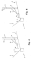
- the position of said body (6) is suitably chosen so that it does not intercept the trajectory that the thread-guide rod imposes on the thread when the latter is to be wound over the belts (3) of the drum (2), as illustrated in Fig. 4 (position A), and it does intercept the said trajectory (position B in Fig. 5) when the thread is to be removed from the thread-guide rod.
- the body (6) is sufficiently distant from the group of channels (5) to allow the thread (F) under work to remain within the guide (42) formed in the wheel (41) and, thereby, to allow the normal winding of the thread over the drum (2).
- the body (6) In the position (B) of Fig. 5, the body (6) is closer to the group of channels (5), so that it intercepts the trajectory of the thread (F) by changing the orientation thereof in the length between the group of channels (5) and the thread-guiding portion (42) presented by the rod (4): this is sufficient for the thread (f) to escape from the guide (42) thus leaving the rod (4) and be recovered in the respective channel of group the (5).
- the procedures for the recovery of the threads after these have been unloaded from the thread-guide rod are known to those skilled in the art and will not, therefore, be described in further details.
- the said body (6) may consist of two parallel metal rods (6c, 6d) lying above the group of channels (5), welded to each other at their ends and connected with the inner surface (100) of the shield (10) by means of two arms (61): each of said arms (61) being, on one end, fixed to the rod (6d) and, on the other, connected with the inner surface (100) of shield (10) via a hinge (16) having its axis orthogonal to the longitudinal axis of the drum (2).
- the two arms (61) support the two rods (6c and 6d) of the body (6) thereby allowing it to move from and to the group of channels (5) via the hinges (16) and a pair of electromagnets (7) which act, as best described later on, on two corresponding surfaces (60) of ferromagnetic material which the body (6) exhibit outside the group of channels (5): each of said arms (61) being also elastically engaged with the shield (10).
- each arm (61) can be engaged with the shield (10) via a corresponding elastic tension bar (63) which causes the body - when the electromagnets are activated (that is, during the winding of a thread over the warper's drum) - to reach the said position (A) and - when the electromagnets are deactivated (that is, after the body has reached the position (B) - to resume the position (A).
- the electromagnets (7) can be fixed to the inner surface (100) of the shield (10) in correspondence of the surfaces (60) exhibited by the body (6).
- the electromagnets (7) When it is desired to unload a thread (F) from the thread-guide rod, the electromagnets (7) are activated, and the magnetic force thus generated attracts the surfaces (60) towards the electromagnets.
- the electromagnets (7) are connectable to the same programmable electronic unit which controls the operation of the means for the presentation and recovery of the threads (F). Such unit is known to those skilled in the art and will not, therefore, be described in greater detail.
- the activation of the actuators (7) that is, the moving of body (6) to the position (B) for the release of a thread (F) from the thread-guide rod (4), can be operated at any instant of the work cycle.
- the extension of body (6) above the group of channels (5) for the presentation and recovery of the threads (F), allows the release of the thread (F) to be unloaded at any instant between its input (I) into, and respectively exit (U) from the area of the group (5), which makes it possible to reduce the time elapsing between the unloading of a thread and the loading of another one.
- the means for moving the body (6) to allow the positioning thereof to the said positions for releasing (position B) and winding (position A) the thread may be of any suitable type.
- the two rods (6c, 6d) of body (6) delimit an opening or window (600) above the group of channels (5) so that the actuation of the means for the presentation and recovery of the threads is by no means prevented or hindered.
Landscapes
- Engineering & Computer Science (AREA)
- Textile Engineering (AREA)
- Warping, Beaming, Or Leasing (AREA)
Applications Claiming Priority (2)
| Application Number | Priority Date | Filing Date | Title |
|---|---|---|---|
| ITFI20020180 ITFI20020180A1 (it) | 2002-09-26 | 2002-09-26 | Dispositivo per lo sgancio dei fili da un'asta guidafili per orditoi |
| ITFI20020180 | 2002-09-26 |
Publications (1)
| Publication Number | Publication Date |
|---|---|
| EP1403407A1 true EP1403407A1 (fr) | 2004-03-31 |
Family
ID=11442324
Family Applications (1)
| Application Number | Title | Priority Date | Filing Date |
|---|---|---|---|
| EP20030425587 Withdrawn EP1403407A1 (fr) | 2002-09-26 | 2003-09-10 | Dispositif pour libérer des fils d'une tige guide-fil pour ourdissoirs |
Country Status (2)
| Country | Link |
|---|---|
| EP (1) | EP1403407A1 (fr) |
| IT (1) | ITFI20020180A1 (fr) |
Citations (5)
| Publication number | Priority date | Publication date | Assignee | Title |
|---|---|---|---|---|
| WO1991019030A1 (fr) * | 1990-05-30 | 1991-12-12 | Hergeth Hollingsworth Gmbh | Ourdissoir de chaines courtes |
| EP0832998A1 (fr) * | 1996-10-31 | 1998-04-01 | Suzuki Warper Ltd. | Dispositif pour la rentrée rapide de fil dans les canaux des ourdissoirs avec un système d'ourdissage des fils l'un après l'autre |
| EP0882820A1 (fr) * | 1997-06-03 | 1998-12-09 | Suzuki Warper Ltd. | Ourdissoir d'échantillonnage contrÔlé électroniquement avec dispositif de changement de fil |
| EP1036867A1 (fr) * | 1999-02-23 | 2000-09-20 | Age s.n.c. di Vieri A. & C. | Dispositif pour assister le retour des fils dans leurs canneaux de présentation respectifs dans les ourdissoirs de type fil par fil |
| EP1136602A1 (fr) * | 2000-03-17 | 2001-09-26 | Suzuki Warper Ltd. | Ourdissoir d'échantillonnage contrôlé électroniquement, cantre rotatif et méthode d'ourdissage |
-
2002
- 2002-09-26 IT ITFI20020180 patent/ITFI20020180A1/it unknown
-
2003
- 2003-09-10 EP EP20030425587 patent/EP1403407A1/fr not_active Withdrawn
Patent Citations (5)
| Publication number | Priority date | Publication date | Assignee | Title |
|---|---|---|---|---|
| WO1991019030A1 (fr) * | 1990-05-30 | 1991-12-12 | Hergeth Hollingsworth Gmbh | Ourdissoir de chaines courtes |
| EP0832998A1 (fr) * | 1996-10-31 | 1998-04-01 | Suzuki Warper Ltd. | Dispositif pour la rentrée rapide de fil dans les canaux des ourdissoirs avec un système d'ourdissage des fils l'un après l'autre |
| EP0882820A1 (fr) * | 1997-06-03 | 1998-12-09 | Suzuki Warper Ltd. | Ourdissoir d'échantillonnage contrÔlé électroniquement avec dispositif de changement de fil |
| EP1036867A1 (fr) * | 1999-02-23 | 2000-09-20 | Age s.n.c. di Vieri A. & C. | Dispositif pour assister le retour des fils dans leurs canneaux de présentation respectifs dans les ourdissoirs de type fil par fil |
| EP1136602A1 (fr) * | 2000-03-17 | 2001-09-26 | Suzuki Warper Ltd. | Ourdissoir d'échantillonnage contrôlé électroniquement, cantre rotatif et méthode d'ourdissage |
Also Published As
| Publication number | Publication date |
|---|---|
| ITFI20020180A1 (it) | 2002-12-27 |
Similar Documents
| Publication | Publication Date | Title |
|---|---|---|
| KR19990071437A (ko) | 전자제어샘플정경기 | |
| CS227311B2 (en) | Apparatus for weft metering and retaining in shuttleless weaving looms | |
| CZ283258B6 (cs) | Tkalcovský stav a zanášací brzdička pro tkalcovský stav | |
| CZ283142B6 (cs) | Způsob řízení zanášení útku do prošlupu a tkalcovský stav k provádění tohoto způsobu | |
| EP0882820B1 (fr) | Ourdissoir d'échantillonnage contrôlé électroniquement avec dispositif de changement de fil | |
| JP3721203B2 (ja) | 糸ブレーキ | |
| JPH02242947A (ja) | 織機の緯糸制動装置 | |
| EP1403407A1 (fr) | Dispositif pour libérer des fils d'une tige guide-fil pour ourdissoirs | |
| US4744394A (en) | Weft yarn store for looms | |
| EP3753886B1 (fr) | Dispositif et procédé de commande d'un ballon lors du déroulement d'un fil d'une bobine | |
| JP2009068157A (ja) | 織機用の切断デバイスおよびその動作方法 | |
| JP7017991B2 (ja) | グリッパ織機における疑似耳部の無い緯糸操作装置 | |
| EP0607147B1 (fr) | Alimentateur de trame pour griffe et metier a tisser a projectile | |
| BE1008376A3 (nl) | Weefmachine met afvallint. | |
| EP4431428A1 (fr) | Unité de détection de tension pour un ensemble de fils impliqués dans un processus textile, et appareil d'alimentation en fil comprenant l'unité | |
| US1783947A (en) | Stop mechanism for detecting irregularities in wire ferding | |
| US3172611A (en) | Tape reeler | |
| JP5255572B2 (ja) | 経糸帯の帯幅内において、糸を位置決めするための装置及び部分整経方法 | |
| EP1312707B1 (fr) | Ourdissoir et méthode d'ourdissage | |
| EP1036867B1 (fr) | Dispositif pour assister le retour des fils dans leurs canneaux de présentation respectifs dans les ourdissoirs de type fil par fil | |
| EP2349896B1 (fr) | Frein de fil et son procédé d'utilisation | |
| JP4969296B2 (ja) | 糸巻付切替手段付サンプル整経機及び整経方法 | |
| US6671937B1 (en) | Rotary creel for electronically controlled sample warper | |
| EP1293593B1 (fr) | Dispositif de support pour un ourdissoir | |
| US3526254A (en) | Method and apparatus for monitoring plural weft threads in a loom |
Legal Events
| Date | Code | Title | Description |
|---|---|---|---|
| PUAI | Public reference made under article 153(3) epc to a published international application that has entered the european phase |
Free format text: ORIGINAL CODE: 0009012 |
|
| AK | Designated contracting states |
Kind code of ref document: A1 Designated state(s): AT BE BG CH CY CZ DE DK EE ES FI FR GB GR HU IE IT LI LU MC NL PT RO SE SI SK TR |
|
| AX | Request for extension of the european patent |
Extension state: AL LT LV MK |
|
| 17P | Request for examination filed |
Effective date: 20040622 |
|
| AKX | Designation fees paid |
Designated state(s): DE |
|
| STAA | Information on the status of an ep patent application or granted ep patent |
Free format text: STATUS: THE APPLICATION IS DEEMED TO BE WITHDRAWN |
|
| 18D | Application deemed to be withdrawn |
Effective date: 20070401 |