EP1403616A1 - Angular velocity sensor - Google Patents
Angular velocity sensor Download PDFInfo
- Publication number
- EP1403616A1 EP1403616A1 EP20030730826 EP03730826A EP1403616A1 EP 1403616 A1 EP1403616 A1 EP 1403616A1 EP 20030730826 EP20030730826 EP 20030730826 EP 03730826 A EP03730826 A EP 03730826A EP 1403616 A1 EP1403616 A1 EP 1403616A1
- Authority
- EP
- European Patent Office
- Prior art keywords
- electrode
- angular velocity
- piezoelectric thin
- velocity sensor
- thin film
- Prior art date
- Legal status (The legal status is an assumption and is not a legal conclusion. Google has not performed a legal analysis and makes no representation as to the accuracy of the status listed.)
- Granted
Links
Images



Classifications
-
- G—PHYSICS
- G01—MEASURING; TESTING
- G01C—MEASURING DISTANCES, LEVELS OR BEARINGS; SURVEYING; NAVIGATION; GYROSCOPIC INSTRUMENTS; PHOTOGRAMMETRY OR VIDEOGRAMMETRY
- G01C19/00—Gyroscopes; Turn-sensitive devices using vibrating masses; Turn-sensitive devices without moving masses; Measuring angular rate using gyroscopic effects
- G01C19/56—Turn-sensitive devices using vibrating masses, e.g. vibratory angular rate sensors based on Coriolis forces
- G01C19/5642—Turn-sensitive devices using vibrating masses, e.g. vibratory angular rate sensors based on Coriolis forces using vibrating bars or beams
- G01C19/5663—Manufacturing; Trimming; Mounting; Housings
-
- G—PHYSICS
- G01—MEASURING; TESTING
- G01C—MEASURING DISTANCES, LEVELS OR BEARINGS; SURVEYING; NAVIGATION; GYROSCOPIC INSTRUMENTS; PHOTOGRAMMETRY OR VIDEOGRAMMETRY
- G01C19/00—Gyroscopes; Turn-sensitive devices using vibrating masses; Turn-sensitive devices without moving masses; Measuring angular rate using gyroscopic effects
- G01C19/56—Turn-sensitive devices using vibrating masses, e.g. vibratory angular rate sensors based on Coriolis forces
- G01C19/5607—Turn-sensitive devices using vibrating masses, e.g. vibratory angular rate sensors based on Coriolis forces using vibrating tuning forks
- G01C19/5628—Manufacturing; Trimming; Mounting; Housings
Definitions
- the present invention relates to an angular velocity sensor used in an attitude control, navigation system or the like such as an aircraft, automobile, robot, ship, vehicle, etc.
- Fig. 8 is a perspective view of a conventional angular velocity sensor.
- angular velocity sensor 101 comprises tuning-fork 102 made from non-piezoelectric material such as silicone, lower electrode 106 disposed on arm 103, arm 104, substrate 105, and arm 103, lower electrode 107 disposed on arm 104, piezoelectric thin film 108 disposed on lower electrode 106, piezoelectric thin film 109 disposed on lower electrode 107, upper electrode 110 and upper electrode 111 disposed on piezoelectric thin film 108, upper electrode 112 and upper electrode 113 disposed on piezoelectric thin film 109.
- applying AC voltage the upper electrodes 110, 111, 112, and 113 causes the tuning-fork 102 to resonate.
- the tuning-fork 102 of the above angular velocity sensor 101 has two perpendicular oscillation modes (oscillation mode in X direction and oscillation mode in Z direction).
- the tuning-fork 102 is driven in only one oscillation mode (for example, oscillation mode in X direction).
- oscillation mode for example, oscillation mode in X direction.
- the tuning-fork 102 is excited in another (Z-direction) oscillation mode due to Corioli's force.
- the angular velocity sensor 101 utilizes this principle.
- the resonance frequencies in the two perpendicular oscillation modes (oscillation mode in X direction and oscillation mode in Z direction) of the tuning-fork 102 are required to be apart from each other.
- the resonance frequencies in the two perpendicular oscillation modes (oscillation mode in X direction and oscillation in Z direction ) of the tuning-fork 102 are close to each other.
- the two resonance frequencies are desirable to be close enough to each other to such extent that they are free from coupling.
- the sensitivity and reliability of the detection signal with respect to the angular velocity applied there has been no documents that include considerations from the viewpoints of difference in elastic modulus depending upon the crystal orientation of the material for the tuning-fork and of resonance frequencies, including the above-mentioned U.S. Patent No. 5438231.
- Resonance frequency f is represented by (formula 1), where c is elastic modulus, ⁇ is density, d is arm width, and I is arm length. f ⁇ c/ ⁇ * d/1 2
- An angular velocity sensor comprising an vibrator, wherein the vibrator is formed of a silicone substrate having a crystal orientation (100) as a main face, and a face nearly perpendicular to the driving direction of the vibrator corresponds to a crystal orientation where elastic modulus is less in variation as against deflection of azimuth angle.
- the present invention is intended to solve the above problems of the conventional system, and the object of the invention is to provide an angular velocity sensor which is able to reduce the variations of driving resonance frequency of the vibrator and to improve the reliability of the sensitivity of detection signal with respect to the angular velocity applied.
- the angular velocity sensor of the present invention has an vibrator, but in the preferred embodiment shown below, an example using a tuning-fork as an vibrator is described.
- Fig. 1 is a perspective view of an angular velocity sensor in the preferred embodiment 1 of the present invention.
- Fig. 2 is a sectional view of the angular velocity sensor along the A - A line of Fig. 1.
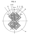
- Fig. 3 is an layout drawing of angular velocity sensors in a silicone substrate.
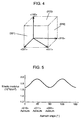
- Fig. 4 is a crystal orientation diagram of a silicone substrate shown in Fig. 3.
- Fig. 5 is a characteristic graph showing the relationship between the elastic modulus and azimuth angle of the silicone substrate shown in Fig. 3.
- Arrow X, arrow Y, and arrow Z of Fig. 1 represent three perpendicular directions respectively. Also, in the following description, the arrow X, arrow Y, and arrow Z are respectively referred to as direction X, direction Y, and direction Z as well.
- tuning-fork 4 as an vibrator having two parallel arms, arm 1 and arm 2, and base 3 which connects these two arms, arm 1 and arm 2, is made of silicone that is non-piezoelectric material.
- Main face 5 of tuning-fork 4 corresponds to crystal orientation (100) of silicone substrate 30. Also, on the basis of orientation-flat 31 of silicone substrate 30 shown in Fig.
- the main face 5 is configured in that respective side 6 and side 7 of the arm 1 and arm 2 correspond to crystal orientation (001), and a face perpendicular to the lengthwise direction (Y direction) of arm 1 and arm 2 corresponds to crystal orientation (010).
- the first electrode 10 is located at the main face 5 of arm 1 and disposed inside the center line 8 of arm 1.
- the second electrode 11 is located at the main face 5 of arm 1 and disposed outside the center line 8.
- the first electrode 10 and the second electrode 11 are spaced apart from each other.
- the first electrode 12 is located at the main face 5 of arm 2 and disposed inside the center line 9 of arm 2.
- the second electrode 13 is located at the main face 5 of arm 2 and disposed outside the center line 9. The first electrode 12 and the second electrode 13 are spaced apart from each other.
- the first piezoelectric thin films 14, 16 are located inside the center lines 8, 9 respectively, and disposed on the first electrodes 10, 12 respectively.
- the second piezoelectric thin films 15, 17 are located outside the center lines 8, 9 respectively, and disposed on the second electrodes 11, 13 respectively.
- the third electrodes 18, 20 are disposed on the first piezoelectric thin films 14, 16 respectively.
- the fourth electrodes 19, 21 are disposed on the second piezoelectric thin films 15, 17 respectively.
- the driving section comprises the first electrodes 10, 12, the second electrodes 11, 13, the first piezoelectric thin films 14, 16, the second piezoelectric thin films 15, 17, the third electrodes 18, 20, and the fourth electrodes 19, 21.
- the fifth electrode 22 is located at the main face 5 of arm 1 and disposed a little closer to the base 3. Also, the fifth electrode 22 is spaced apart from the first electrode 10 and the second electrode 11.
- the sixth electrode 23 is disposed on the third piezoelectric thin film 26 disposed on the fifth electrode 22.
- the third piezoelectric thin film 26 is hidden by the sixth electrode 23 and invisible in Fig. 1 and Fig. 3, but it is revealed in the sectional view of Fig. 6D.
- the fifth electrode 24 is located at the main face 5 of arm 2 and disposed a little closer to base 3. Also, the fifth electrode 24 is spaced apart from the first electrode 12 and the second electrode 13.
- the sixth electrode 25 is disposed on the third piezoelectric thin film 27 disposed on the fifth electrode 24.
- the third piezoelectric thin film 27 is hidden by the sixth electrode 25 and invisible in Fig. 1 and Fig. 3, but it is revealed in the sectional view of Fig. 6D.
- the detecting section comprises the fifth electrodes 22, 24, the third piezoelectric thin films 26, 27, and the sixth electrodes 23, 25.
- the angular velocity sensor 51 is configured as described above.
- the polarization of the first piezoelectric thin films 14, 16, the second piezoelectric thin films 15, 17, and the third piezoelectric thin films 26, 27 takes place in a direction from the first electrodes 10, 12, the second electrodes 11, 13, and the fifth electrodes 22, 24 toward the third electrodes 18, 20, the fourth electrodes 19, 21, and the sixth electrodes 23, 25.
- the direction of polarization is maintained in a constant direction even with the application of DC voltage discontinued. This is called spontaneous polarization.
- the first piezoelectric thin films 14, 16, the second piezoelectric thin films 15, 17, and the third piezoelectric thin films 26, 27 have such spontaneous polarization, and the third electrodes 18, 20, the fourth electrodes 19, 21, and the sixth electrodes 23, 25 are higher in electric potential than the first electrodes 10, 12, the second electrodes 11, 13, and the fifth electrodes 22, 24, then the first piezoelectric thin films 14, 16, the second piezoelectric thin films 15, 17, and the third piezoelectric thin films 26, 27 respectively act in the direction of relieving the polarization. Accordingly, the first piezoelectric thin films 14, 16, the second piezoelectric thin films 15, 17, and the third piezoelectric thin films 26, 27 shrink in a direction parallel with polarization and expand in a direction perpendicular thereto.
- the third electrodes 18, 20, the fourth electrodes 19, 21, and the sixth electrodes 23, 25 are lower in electric potential than the first electrodes 10, 12, the second electrodes 11, 13, and the fifth electrodes 22, 24, then the first piezoelectric thin films 14, 16, the second piezoelectric thin films 15, 17, and the third piezoelectric thin films 26, 27 expand in a direction parallel with polarization and shrink in a direction perpendicular thereto.
- the first electrode 10 being GND electrode or virtual GND electrode
- the first piezoelectric thin film 14 expands and shrinks in Y-axis direction.
- the driving section arranged inside on the arm 1, and similar operations are executed with respect to the driving section disposed outside on the arm 1, and the driving sections disposed inside and outside on the arm 2.
- the arms 1, 2 have resonance frequencies depending upon the shape.
- the frequencies of AC voltage applied to the third electrodes 18, 20 and the fourth electrodes 19, 21 are equalized to the resonance frequency of the shape, the arms 1, 2 are driven to resonate in the X direction (driving direction) of the arm 1, 2.
- the arms 1, 2 flex reversely to each other in Z direction (detecting direction) due to Corioli's force.
- Such flexure causes reverse electric charge to be generated at the third piezoelectric thin films 26, 27 respectively disposed on the arms 1, 2.
- the reverse electric charge is detected by the sixth electrodes 23, 25, thereby obtaining an output corresponding to the angular velocity applied.
- the arm 1, 2 has an oscillation mode for moving in X direction (driving direction) and an oscillation mode for moving in Z direction (detecting direction). With the two oscillation modes set to same frequency, resonance is generated at the detection side (Z direction) as well due to driving resonation, and it becomes difficult to distinguish distortion generated due to Corioli's force. Therefore, it is necessary to suppress the coupling of resonance frequency at the detection side (Z direction) and resonance frequency at the driving side (X direction) by setting the resonance frequency at the detection side (Z direction) to a level slightly different from the resonance frequency at the driving side (X direction).
- an example of a configuration wherein the width in the driving direction (X direction) of the arm 1, 2 is greater than the thickness in the detecting direction (Z direction) is described in the following.
- the width of arm 1, 2 is 0.2mm, and the thickness is 0.19mm.
- the resonance frequency in the driving direction (X direction) of the tuning-fork 4 is 22 kHz for example, and the resonance frequency in the detecting direction (Z direction) is 20 kHz for example.
- the crystal orientation (100), crystal orientation (010), crystal orientation (001) of silicone are in perpendicular relation with each other, and ⁇ 010> azimuth and ⁇ 011> azimuth, ⁇ 011> azimuth and ⁇ 001> azimuth are respectively 45° different from each other.
- Fig. 5 shows the relationship between the face angle and elastic modulus of silicone.
- the horizontal axis represents the azimuth angle on the basis of ⁇ 010> azimuth
- the vertical axis represents the elastic modulus.
- the elastic modulus of crystal orientation (100) silicone, near ⁇ 010> azimuth (around azimuth angle 0°), near ⁇ 011> azimuth (around azimuth angle 45°), and near ⁇ 001> azimuth (around azimuth angle 90°) is less in variation as against the azimuth angle.
- ⁇ 010> azimuth and ⁇ 001> azimuth are same in elastic modulus.
- the elastic modulus of silicone of crystal orientation (100) in cycles of azimuth angle 45°, the elastic modulus is rather less dependent on the azimuth angle, and elastic modulus itself varies in cycles of face angle 90°. That is, as shown in Fig. 3, the lengthwise direction (Y direction) of the arm 1, 2 of the tuning-fork 4 three-dimensionally formed by using the silicone substrate 30 of crystal orientation (100) is configured to be ⁇ 010> azimuth, and then, the driving direction (X direction) of the tuning-fork 4 corresponds to ⁇ 001> azimuth.
- the elastic modulus can be nearly equalized and it is possible to lessen the variation of elastic modulus as against the deflection of azimuth angle. Accordingly, the variation of resonance frequency in the driving direction (X direction) is reduced and the accuracy can be improved, and as a result, the sensitivity of detection signal of the angular velocity applied will be improved in reliability. Also, similar effects can be obtained when the lengthwise direction (Y direction) of arm 1, 2 of the tuning-fork 4 is configured to be ⁇ 001> azimuth so that the driving direction (X direction) corresponds to ⁇ 010> azimuth.
- Fig. 6A to Fig. 6H are the manufacturing steps described by using the D - D section of the angular velocity sensor shown in Fig. 3.
- silicone substrate 30 of crystal orientation (100) and about 200 ⁇ m in thickness is prepared.
- an alloy layer of noble metal and liable-to-oxidize material is formed in thickness of about 2000 ⁇ by sputtering or vacuum evaporation on the main face 5 of silicone substrate 30.
- platinum (Pt) - titanium (Ti), iridium (Ir) - titanium (Ti) or thae like is available.
- Lower electrode layer 40 is formed in this way.
- piezoelectric material such as lead titanate zirconate (PZT) in thickness of about 1 to 4 ⁇ m, thereby forming piezoelectric thin film 41.
- PZT lead titanate zirconate
- upper electrode layer 42 made from materials such as gold (Au), chrome (Cr), aluminum (Al), copper (Cu), and titanium (Ti) in thickness of about 2000 ⁇ .
- resist 43 is patterned on upper electrode layer 42.
- the resist 43 is patterned for the purpose of forming the predetermined shapes, that is, the third electrode 18, 20, the fourth electrode 19, 21, the sixth electrode 23, 25, the first piezoelectric thin film 14, 16, the second piezoelectric thin film 15, 17, and the third piezoelectric thin film 26, 27 by means of photolithography technology.
- the upper electrode layer 42 and the piezoelectric thin film 41 are etched as shown in Fig. 6D.
- the resist 44 is patterned.
- the resist 44 is formed for the purpose of forming the predetermined shapes, that is, the first electrode 10, 12, the second electrode 11, 13, and the fifth electrode 22, 24 by means of photolithography technology.
- the resist 44 is formed and patterned so as to cover the third electrode 18, 20, the fourth electrode 19, 21, the sixth electrode 23, 25, the first piezoelectric thin film 14, 16, the second piezoelectric thin film 15, 17, and the third piezoelectric thin film 26, 27.
- the lower electrode layer 40 is etched into a predetermined shape as shown in Fig. 6F.
- resist 45 is patterned, which is formed so as to cover the first electrode 10, 12, the second electrode 11, 13, the fifth electrode 22, 24, the first piezoelectric thin film 14, 16, the second piezoelectric thin film 15, 17, the third piezoelectric thin film 26, 27, the third electrode 18, 20, the fourth electrode 19, 21, the sixth electrode 23, 25, and the main face 5 of silicone substrate 30.
- the resist 45 is patterned for the purpose of forming the tuning-fork 4 made from silicone of a predetermined shape by using photolithography technology.
- the silicone substrate 30 is subjected to inductive coupling type reactive ion etching.
- two kinds of gasses are used at least.
- Two or more kinds of gasses at least include a gas that promotes etching and a gas that suppresses etching.
- the promotion and suppression of etching can be accurately executed.
- etching can be executed only in a direction perpendicular to the main face 5 of silicone substrate 30. Subsequently, side faces 46, 47 perpendicular to the main face 5 of silicone substrate 30 can be obtained.
- tuning-forks 4 are arranged in the silicone substrate 30 at nearly same intervals D1, D2, D3.
- the reactive ion etching executed is uniform in width, resulting in a stable state of etching, and the cut section of the tuning-fork 4 is enhanced in verticality. That is, the dimensional accuracy of width is improved with respect to the machining method of arms 1, 2, and the resonance frequency in the driving direction (X direction) of the tuning-fork 4 becomes less in variation, thereby ensuring higher accuracy, and the sensitivity of detecting the angular velocity applied is further improved in reliability.
- the lower electrode layer 40 it is more preferable to comprise Ti layer disposed at the bottom (silicone 30) side and Pt - Ti layer or Ir - Ti layer disposed at the top (the first piezoelectric thin film 14, 16, the second piezoelectric thin film 15, 17, the third piezoelectric thin film 26, 27) side.
- the Ti layer is in tight contact with silicone and Pt - Ti layer or Ir - Ti layer, and the Pt - Ti layer or Ir - Ti layer can improve the orientation of piezoelectric thin film such as PZT.
- a configuration with piezoelectric thin film 41 directly disposed on the lower electrode layer 40 made from platinum (Pt) - titanium (Ti) or iridium (Ir) - titanium (Ti) is described as an example.
- Pt platinum
- Ti titanium
- Ir iridium
- Ti titanium
- PLMT lead titanate layer with lanthanum
- Mg magnesium
- PZT lead titanate zirconate
- PZT lead titanate zirconate
- Mg magnesium
- Nb niobium
- Mn manganese Due to this configuration, same as for PZT, the piezoelectric constant of the piezoelectric thin film is larger, the electric-mechanic conversion efficiency is higher, and it is possible to improve the sensitivity of detection signal with respect to the angular velocity applied.
- the piezoelectric thin film 41 comprises PZT or PZT type to which is added at least one of those selected from Mg, Nb, Mn.
- One face of the crystalline structure of the piezoelectric thin film 41 is preferentially oriented in parallel with the main face of arm 1, 2. According to the level of preferential orientation, the angles of a plurality of polarizing vectors are equalized as against the direction of the driving electric field applied, thereby stabilizing the detection signal with respect to the angular velocity applied.
- the crystalline structure of piezoelectric thin film 41 is a rhombohedral structure or a tetragonal structure, and the (001) face thereof is preferentially oriented in parallel with the main face of arm 1, 2. Due to the structure, the piezoelectric characteristic of the piezoelectric thin film 41 will not have non-linearity to the applied voltage, and it is possible to excecute more reliable drive of the angular velocity sensor and to detect the angular velocity.
- the crystalline structure of the piezoelectric thin film 41 is a rhombohedral structure or a tetragonal structure, and the (111) face is preferentially oriented in parallel with the main face of arm 1, 2. Due to this structure, the piezoelectric characteristic of piezoelectric thin film 41 will have non-linearity to the applied voltage, but the higher the voltage to be applied, higher is the piezoelectric characteristic, and it is effective when greater driving amplitude is required.
- the configuration described as an example is such that the driving section is disposed at closer to the end side than the center of arm 1, 2, and the detecting section is disposed between the center of arm 1, 2 and near the base 3.
- Fig. 7 is a layout drawing of a silicone substrate in the preferred embodiment 2 of an angular velocity sensor of the present invention.
- same component parts as those in the preferred embodiment 1 are given same reference numerals, and the detailed description is omitted, and only differences will be described in detail.
- the difference from the preferred embodiment 1 is the arrangement of the angular velocity sensor in the silicone substrate.
- orientation-flat 50 is perpendicular to the main face 5 of silicone substrate 30 of crystal orientation (100), and also, perpendicular to ⁇ 01-1> azimuth. Since the selection is made so that the lengthwise direction (Y direction) of arm 1, 2 corresponds to ⁇ 01-1> azimuth, the driving direction (X direction) corresponds to ⁇ 011> azimuth. Accordingly, as shown in Fig. 5, ⁇ 011> azimuth that corresponds to the driving direction (X direction) becomes less in variation of elastic modulus as against the angular deflection of azimuth, and the elastic modulus is further increased with respect to the driving direction (X direction).
- the tuning-fork 4 comprising two arms 1, 2, and base 3 has been described.
- the present invention it is also possible for the present invention to have one arm or three or more arms. That is, selecting a crystal orientation that lessens the variation of elastic modulus as against the angular deflection of azimuth that is the technical concept of the present invention, it is possible to lessen the variation of resonance frequency in the driving direction and to improve the reliability of the sensitivity of detection signal with respect to the angular velocity applied.
- an angular velocity sensor comprising an vibrator
- the vibrator is formed of a silicone substrate with crystal orientation (100) as its main face, and is further configured in that a face nearly perpendicular to the driving direction of the vibrator corresponds to a crystal orientation where elastic modulus is less dependent upon azimuth angle. Accordingly, even when the crystal orientation is somewhat deflected, the variations of driving resonance frequency of the vibrator can be reduced to a low level, and it is possible to improve the reliability of the sensitivity of detection signal with respect to the angular velocity applied.
- the selection is made so that the side face of the arm corresponds to a crystal orientation where elastic modulus is less dependent upon azimuth angle. In this way, even when the crystal orientation is somewhat deflected, the variations of driving resonance frequency of the tuning-fork can be reduced to a low level, and it is possible to improve the reliability of the sensitivity of detection signal with respect to the angular velocity applied.
- the side face of the arm corresponds to a crystal orientation of (010) or (001).
- the variations of driving resonance frequency of the tuning-fork can be reduced to a low level, and it is possible to improve the reliability of the sensitivity of detection signal with respect to the angular velocity applied.
- the side face of the arm corresponds to ⁇ 011> azimuth.
- the variations of driving resonance frequency of the tuning-fork can be reduced to a low level.
- elastic modulus itself is great, the driving resonance frequency of the tuning-fork can be enhanced, and it is possible to improve the reliability of the sensitivity of detection signal with respect to the angular velocity applied and to make the sensitivity itself higher.
- the thickness in the detecting direction (Z direction) of the arm is less than the thickness in the driving direction (X direction).
- the first electrode, the second electrode, and the fifth electrode are formed of alloy layers made from noble metal and liable-to-oxide material.
- the alloy layer made from noble metal and liable-to-oxide material can improve the orientation of piezoelectric thin film such as PZT.
- the noble metal comprises Pt or Ir.
- the noble metal comprising Pt or Ir can improve the orientation of piezoelectric thin film such as PZT.
- the alloy layer made from noble metal and liable-to-oxide material is formed of Pt - Ti layer or Ir - Ti layer.
- the alloy layer comprising Pt - Ti layer or Ir - Ti layer can further improve the orientation of piezoelectric thin film such as PZT.
- the first electrode, the second electrode, and the fifth electrode are formed of Ti layer disposed at the bottom and Pt - Ti layer or Ir - Ti layer disposed at the top.
- the Ti layer is in tight contact with silicone and Pt - Ti layer or Ir - Ti layer, and Pt - Ti layer or Ir - Ti layer can improve the orientation of piezoelectric thin film such as PZT.
- a lead titanate layer with lanthanum (La) and magnesium (Mg) added, is disposed between Pt - Ti layer and piezoelectric thin film, or between Ir - Ti layer and piezoelectric thin film.
- La lanthanum
- Mg magnesium
- the piezoelectric thin film comprises lead titanate zirconate (PZT), or lead titanate zirconate (PZT) type to which at least one of Mg, Nb, and Mn is added.
- PZT lead titanate zirconate
- PZT lead titanate zirconate
- one face of the crystalline structure is preferentially oriented to the main face of the arm. According to the level of preferential orientation, the angles of a plurality of polarizing vectors are equalized as against the direction of the driving electric field applied, thereby stabilizing the detection signal with respect to the angular velocity applied.
- the crystalline structure is a rhombohedral structure or a tetragonal structure, and the (001) face is preferentially oriented in parallel with the main face of the arm.
- the piezoelectric characteristic of the piezoelectric thin film will not have non-linearity to the applied voltage, and it is possible to excecute more reliable drive of the angular velocity sensor and to detect the angular velocity.
- the crystalline structure is a rhombohedral structure or a tetragonal structure, and the (111) face is preferentially oriented in parallel with the main face of the arm.
- the piezoelectric characteristic of the piezoelectric thin film will have non-linearity to the applied voltage, but the higher the voltage to be applied, higher is the piezoelectric characteristic, and it is effective when greater driving amplitude is required.
- the driving section is disposed between near the center of the main face of at least one of the arms and near the substrate, and the detecting section is disposed closer to the end of the arm than to the first electrode and the second electrode.
- a silicone substrate with crystal orientation (100) as its main face is subjected to vertical etching to form the tuning-fork.
- the angular velocity sensor of the present invention comprises an vibrator formed of a silicone substrate with crystal orientation (100) as its main face, which is configured in that a face nearly perpendicular to the driving direction of the vibrator corresponds to a crystal orientation where elastic modulus is less dependent upon azimuth angle.
- the angular velocity sensor of the present invention is able to lessen the variation of driving resonance frequency of the vibrator and to improve the reliability of the sensitivity of detection signal with respect to the angular velocity applied.
Landscapes
- Engineering & Computer Science (AREA)
- Manufacturing & Machinery (AREA)
- Physics & Mathematics (AREA)
- General Physics & Mathematics (AREA)
- Radar, Positioning & Navigation (AREA)
- Remote Sensing (AREA)
- Gyroscopes (AREA)
Abstract
Description
- The present invention relates to an angular velocity sensor used in an attitude control, navigation system or the like such as an aircraft, automobile, robot, ship, vehicle, etc.
- As a conventional angular velocity sensor, well-known is the one disclosed in U.S. Patent No. 5438231. The angular velocity sensor will be described with reference to Fig. 8.
- Fig. 8 is a perspective view of a conventional angular velocity sensor. In Fig. 8,
angular velocity sensor 101 comprises tuning-fork 102 made from non-piezoelectric material such as silicone,lower electrode 106 disposed onarm 103,arm 104,substrate 105, andarm 103,lower electrode 107 disposed onarm 104, piezoelectricthin film 108 disposed onlower electrode 106, piezoelectricthin film 109 disposed onlower electrode 107,upper electrode 110 andupper electrode 111 disposed on piezoelectricthin film 108,upper electrode 112 andupper electrode 113 disposed on piezoelectricthin film 109. And, applying AC voltage theupper electrodes fork 102 to resonate. - The tuning-
fork 102 of the aboveangular velocity sensor 101 has two perpendicular oscillation modes (oscillation mode in X direction and oscillation mode in Z direction). The tuning-fork 102 is driven in only one oscillation mode (for example, oscillation mode in X direction). In this condition, when rotational angular velocity is applied about the axis (Y axis) perpendicular to the axes (X axis, Z axis) of the two perpendicular oscillation mode, the tuning-fork 102 is excited in another (Z-direction) oscillation mode due to Corioli's force. Theangular velocity sensor 101 utilizes this principle. In the configuration of suchangular velocity sensor 101, in order to obtain highly reliable detection signal with respect to the angular velocity applied, the resonance frequencies in the two perpendicular oscillation modes (oscillation mode in X direction and oscillation mode in Z direction) of the tuning-fork 102 are required to be apart from each other. However, for improving the sensitivity of the detection signal with respect to the angular velocity applied, it is advantageous that the resonance frequencies in the two perpendicular oscillation modes (oscillation mode in X direction and oscillation in Z direction ) of the tuning-fork 102 are close to each other. That is, from the viewpoint of reliability and sensitivity of the detection signal with respect to the angular velocity applied, the two resonance frequencies are desirable to be close enough to each other to such extent that they are free from coupling. However, regarding the sensitivity and reliability of the detection signal with respect to the angular velocity applied, there has been no documents that include considerations from the viewpoints of difference in elastic modulus depending upon the crystal orientation of the material for the tuning-fork and of resonance frequencies, including the above-mentioned U.S. Patent No. 5438231. - The above-mentioned matter is described in detail in the following. Resonance frequency f is represented by (formula 1), where c is elastic modulus, ρ is density, d is arm width, and I is arm length.

- In the above (formula 1), it is clear that the resonance frequency in the X-direction oscillation mode of the tuning-
form 102 varies with elastic modulus c. In the case of the conventional angular sensor, there has been a problem such that elastic modulus c in the X direction (driving direction) of the tuning-fork 102 varies depending upon the face selected as a crystal orientation at the side ofarm - An angular velocity sensor comprising an vibrator,
wherein the vibrator is formed of a silicone substrate having a crystal orientation (100) as a main face, and a face nearly perpendicular to the driving direction of the vibrator corresponds to a crystal orientation where elastic modulus is less in variation as against deflection of azimuth angle. -
- Fig. 1 is a perspective view of the
preferred embodiment 1 of the angular velocity sensor of the present invention. - Fig. 2 is a sectional view along A - A of the angular velocity sensor shown in Fig. 1.
- Fig. 3 is a layout drawing of angular velocity sensors in a silicone substrate in the present invention.
- Fig. 4 is a crystal orientation diagram of a silicone substrate.
- Fig. 5 is a characteristic graph showing the relationship between elastic modulus and azimuth of the silicone substrate.
- Fig. 6 A to Fig. 6 H show the manufacturing steps described by using the D - D section of Fig. 3 for the angular velocity sensor of the present invention.
- Fig. 7 is a layout in the silicone substrate in the
preferred embodiment 2 of the angular velocity sensor of the present invention. - Fig. 8 is a perspective view of a conventional angular velocity sensor.
- The present invention is intended to solve the above problems of the conventional system, and the object of the invention is to provide an angular velocity sensor which is able to reduce the variations of driving resonance frequency of the vibrator and to improve the reliability of the sensitivity of detection signal with respect to the angular velocity applied.
- The preferred embodiments of the present invention will be described in the following with reference to Fig. 1 to Fig. 7. The angular velocity sensor of the present invention has an vibrator, but in the preferred embodiment shown below, an example using a tuning-fork as an vibrator is described.
- Fig. 1 is a perspective view of an angular velocity sensor in the
preferred embodiment 1 of the present invention. Fig. 2 is a sectional view of the angular velocity sensor along the A - A line of Fig. 1. Fig. 3 is an layout drawing of angular velocity sensors in a silicone substrate. Fig. 4 is a crystal orientation diagram of a silicone substrate shown in Fig. 3. Fig. 5 is a characteristic graph showing the relationship between the elastic modulus and azimuth angle of the silicone substrate shown in Fig. 3. - Arrow X, arrow Y, and arrow Z of Fig. 1 represent three perpendicular directions respectively. Also, in the following description, the arrow X, arrow Y, and arrow Z are respectively referred to as direction X, direction Y, and direction Z as well. As shown in Fig. 1, Fig. 2, and Fig. 3, tuning-
fork 4 as an vibrator having two parallel arms,arm 1 andarm 2, andbase 3 which connects these two arms,arm 1 andarm 2, is made of silicone that is non-piezoelectric material.Main face 5 of tuning-fork 4 corresponds to crystal orientation (100) ofsilicone substrate 30. Also, on the basis of orientation-flat 31 ofsilicone substrate 30 shown in Fig. 3, themain face 5 is configured in thatrespective side 6 andside 7 of thearm 1 andarm 2 correspond to crystal orientation (001), and a face perpendicular to the lengthwise direction (Y direction) ofarm 1 andarm 2 corresponds to crystal orientation (010). Thefirst electrode 10 is located at themain face 5 ofarm 1 and disposed inside thecenter line 8 ofarm 1. Thesecond electrode 11 is located at themain face 5 ofarm 1 and disposed outside thecenter line 8. Thefirst electrode 10 and thesecond electrode 11 are spaced apart from each other. Thefirst electrode 12 is located at themain face 5 ofarm 2 and disposed inside thecenter line 9 ofarm 2. Thesecond electrode 13 is located at themain face 5 ofarm 2 and disposed outside thecenter line 9. Thefirst electrode 12 and thesecond electrode 13 are spaced apart from each other. The first piezoelectricthin films center lines first electrodes thin films center lines second electrodes third electrodes thin films fourth electrodes thin films - The driving section comprises the
first electrodes second electrodes thin films thin films third electrodes fourth electrodes - The
fifth electrode 22 is located at themain face 5 ofarm 1 and disposed a little closer to thebase 3. Also, thefifth electrode 22 is spaced apart from thefirst electrode 10 and thesecond electrode 11. Thesixth electrode 23 is disposed on the third piezoelectricthin film 26 disposed on thefifth electrode 22. The third piezoelectricthin film 26 is hidden by thesixth electrode 23 and invisible in Fig. 1 and Fig. 3, but it is revealed in the sectional view of Fig. 6D. Similarly, thefifth electrode 24 is located at themain face 5 ofarm 2 and disposed a little closer tobase 3. Also, thefifth electrode 24 is spaced apart from thefirst electrode 12 and thesecond electrode 13. Thesixth electrode 25 is disposed on the third piezoelectricthin film 27 disposed on thefifth electrode 24. The third piezoelectricthin film 27 is hidden by thesixth electrode 25 and invisible in Fig. 1 and Fig. 3, but it is revealed in the sectional view of Fig. 6D. - The detecting section comprises the
fifth electrodes thin films sixth electrodes - The
angular velocity sensor 51 is configured as described above. - The operational principle of the angular velocity sensor. 51 will be described in the following.
- In Fig. 1 and Fig. 2, when DC voltage of about 20V is applied respectively between the
first electrode 10 and thethird electrode 18, between thefirst electrode 12 and thethird electrode 20, between thesecond electrode 11 and thefourth electrode 19, and between thesecond electrode 13 and thefourth electrode 21, then polarization takes place in a constant direction with respect to the first piezoelectricthin films thin films fifth electrode 22 and thesixth electrode 23, and between thefifth electrode 24 and thesixth electrode 25, then polarization takes place in a constant direction with respect to the third piezoelectricthin films - For example, when DC voltage is applied so that the
first electrodes second electrodes fifth electrodes thin films thin films thin films first electrodes second electrodes fifth electrodes third electrodes fourth electrodes sixth electrodes thin films thin films thin films third electrodes fourth electrodes sixth electrodes first electrodes second electrodes fifth electrodes thin films thin films thin films thin films thin films thin films third electrodes fourth electrodes sixth electrodes first electrodes second electrodes fifth electrodes thin films thin films thin films - Accordingly, the
first electrode 10 being GND electrode or virtual GND electrode, when AC voltage is applied to thethird electrode 18, the first piezoelectricthin film 14 expands and shrinks in Y-axis direction. Described above is the driving section arranged inside on thearm 1, and similar operations are executed with respect to the driving section disposed outside on thearm 1, and the driving sections disposed inside and outside on thearm 2. - Also, with AC voltages different in phase by 180° from each other applied to the
third electrode 18 and thefourth electrode 19 shown in Fig. 1 and Fig. 2, the first piezoelectricthin film 14 expands, while the second piezoelectricthin film 15 shrinks. On the contrary, when the first piezoelectricthin film 14 shrinks, the second piezoelectricthin film 15 expands. - On the basis of the above principles, AC voltages same in phase being applied to the
third electrodes third electrodes fourth electrodes arm 1 and thearm 2 are subjected to tuning-fork oscillation in a direction (X direction) opposite to each other. - Also, the
arms third electrodes fourth electrodes arms arm arms thin films arms sixth electrodes - The
arm - However, if the frequency is set to a greatly different level, even when Corioli's force is generated at the detection side (Z direction), great oscillation will not be generated at the detection side (Z direction) because the reconance frequency at the detection side (Z derection) is apart from the resonance frequency at the driving side (X direction). That is, it is necessary to set the resonance frequency at the driving side (X direction) and the resonance frequency at the detection side (Z direction) apart from each other to such extent that they are free from coupling, and to set both frequencies close to each other in order to enhance the sensitivity at the detection side (Z direction).
- In the present preferred embodiment, an example of a configuration wherein the width in the driving direction (X direction) of the
arm arm fork 4 is 22 kHz for example, and the resonance frequency in the detecting direction (Z direction) is 20 kHz for example. - As shown in Fig. 4, the crystal orientation (100), crystal orientation (010), crystal orientation (001) of silicone are in perpendicular relation with each other, and <010> azimuth and <011> azimuth, <011> azimuth and <001> azimuth are respectively 45° different from each other.
- Also, Fig. 5 shows the relationship between the face angle and elastic modulus of silicone. The horizontal axis represents the azimuth angle on the basis of <010> azimuth, and the vertical axis represents the elastic modulus. As shown in Fig. 5, the elastic modulus of crystal orientation (100) silicone, near <010> azimuth (around
azimuth angle 0°), near <011> azimuth (aroundazimuth angle 45°), and near <001> azimuth (aroundazimuth angle 90°), is less in variation as against the azimuth angle. <010> azimuth and <001> azimuth are same in elastic modulus. Thus, regarding the elastic modulus of silicone of crystal orientation (100), in cycles ofazimuth angle 45°, the elastic modulus is rather less dependent on the azimuth angle, and elastic modulus itself varies in cycles offace angle 90°. That is, as shown in Fig. 3, the lengthwise direction (Y direction) of thearm fork 4 three-dimensionally formed by using thesilicone substrate 30 of crystal orientation (100) is configured to be <010> azimuth, and then, the driving direction (X direction) of the tuning-fork 4 corresponds to <001> azimuth. Also, since the detecting direction (Z direction) is <100> azimuth, in the driving mode in the driving direction (X direction) and detecting direction (Z direction), the elastic modulus can be nearly equalized and it is possible to lessen the variation of elastic modulus as against the deflection of azimuth angle. Accordingly, the variation of resonance frequency in the driving direction (X direction) is reduced and the accuracy can be improved, and as a result, the sensitivity of detection signal of the angular velocity applied will be improved in reliability. Also, similar effects can be obtained when the lengthwise direction (Y direction) ofarm fork 4 is configured to be <001> azimuth so that the driving direction (X direction) corresponds to <010> azimuth. - In the above description, aiming at the crystal orientation (100), the relationship between azimuth <100>, azimuth <010>, azimuth <001> at crystal orientation (100) and elastic modulus is described. Also in the case of crystal orientation (010) or crystal orientation (001), elastic modulus varies depending upon azimuth <100>, azimuth <010>, and azimuth <001>. This is because the crystallizability of silicone has a symmetrical axis, and <100>, <010> and <001> are symmetrical axes. Therefore, in the present invention, the main face is (100), but it is also preferable to be (010) or (001). And in this case, only the name of azimuth is changed for convenience sake, including no substantial differences at all. Namely, when a crystal orientation is determined, it directly determines the corresponding three azimuths. And also, at the two crystal orientations, the relationship between azimuth angle and elastic modulus is equivalent to the relationship shown in Fig. 5.
- Next, the method of manufacturing an angular velocity sensor in the present preferred embodiment will be described in the following.
- Fig. 6A to Fig. 6H are the manufacturing steps described by using the D - D section of the angular velocity sensor shown in Fig. 3.
- As shown in Fig. 6A,
silicone substrate 30 of crystal orientation (100) and about 200 µm in thickness is prepared. Subsequently, as shown in Fig. 6B, an alloy layer of noble metal and liable-to-oxidize material is formed in thickness of about 2000Å by sputtering or vacuum evaporation on themain face 5 ofsilicone substrate 30. As the alloy layer of noble metal and liable-to-oxidize material, platinum (Pt) - titanium (Ti), iridium (Ir) - titanium (Ti) or thae like is available.Lower electrode layer 40 is formed in this way. Further, on thelower electrode layer 40 is formed by sputtering piezoelectric material such as lead titanate zirconate (PZT) in thickness of about 1 to 4 µm, thereby forming piezoelectricthin film 41. On the piezoelectricthin layer 41 is formed by sputtering or vacuum evaporationupper electrode layer 42 made from materials such as gold (Au), chrome (Cr), aluminum (Al), copper (Cu), and titanium (Ti) in thickness of about 2000Å. - Next, as shown in Fig. 6C, resist 43 is patterned on
upper electrode layer 42. The resist 43 is patterned for the purpose of forming the predetermined shapes, that is, thethird electrode fourth electrode sixth electrode thin film thin film thin film upper electrode layer 42 and the piezoelectricthin film 41 are etched as shown in Fig. 6D. And, as shown in Fig. 6E, the resist 44 is patterned. The resist 44 is formed for the purpose of forming the predetermined shapes, that is, thefirst electrode second electrode fifth electrode third electrode fourth electrode sixth electrode thin film thin film thin film lower electrode layer 40 is etched into a predetermined shape as shown in Fig. 6F. - Next, as shown in Fig. 6G, resist 45 is patterned, which is formed so as to cover the
first electrode second electrode fifth electrode thin film thin film thin film third electrode fourth electrode sixth electrode main face 5 ofsilicone substrate 30. The resist 45 is patterned for the purpose of forming the tuning-fork 4 made from silicone of a predetermined shape by using photolithography technology. And, as shown in Fig. 6H, thesilicone substrate 30 is subjected to inductive coupling type reactive ion etching. - In the above method of manufacturing an angular velocity sensor, when the resist 43, 44, and 45 shown in Fig. 6C, Fig. 6E, and Fig. 6G are patterned, the position of orientation-flat 31 is <011> azimuth as shown in Fig. 3, and the position of the orientation-flat 31 is adjusted in relation with the photo mask, patterning is executed so that the side faces 46, 47 of the
arms arm silicone substrate 30, the resonance frequency of the driving side (X direction) is higher than the resonance frequency of the detecting side (Z direction). - When the induction coupling type reactive ion etching is executed on the
silicone substrate 30, two kinds of gasses are used at least. Two or more kinds of gasses at least include a gas that promotes etching and a gas that suppresses etching. Thus, the promotion and suppression of etching can be accurately executed. As a result, etching can be executed only in a direction perpendicular to themain face 5 ofsilicone substrate 30. Subsequently, side faces 46, 47 perpendicular to themain face 5 ofsilicone substrate 30 can be obtained. - Further, as shown in Fig. 6H, tuning-
forks 4 are arranged in thesilicone substrate 30 at nearly same intervals D1, D2, D3. Thus, the reactive ion etching executed is uniform in width, resulting in a stable state of etching, and the cut section of the tuning-fork 4 is enhanced in verticality. That is, the dimensional accuracy of width is improved with respect to the machining method ofarms fork 4 becomes less in variation, thereby ensuring higher accuracy, and the sensitivity of detecting the angular velocity applied is further improved in reliability. - In the present preferred embodiment, described is an example using platinum (Pt) - titanium (Ti) or iridium (Ir) - titanium (Ti) for the
lower electrode layer 40 as the first electrode, the second electrode, and the fifth electrode. However, as thelower electrode layer 40, it is more preferable to comprise Ti layer disposed at the bottom (silicone 30) side and Pt - Ti layer or Ir - Ti layer disposed at the top (the first piezoelectricthin film thin film thin film 26, 27) side. In this configuration, the Ti layer is in tight contact with silicone and Pt - Ti layer or Ir - Ti layer, and the Pt - Ti layer or Ir - Ti layer can improve the orientation of piezoelectric thin film such as PZT. - Also, in the present preferred embodiment, a configuration with piezoelectric
thin film 41 directly disposed on thelower electrode layer 40 made from platinum (Pt) - titanium (Ti) or iridium (Ir) - titanium (Ti) is described as an example. However, it is more preferable to be configured in that lead titanate layer with lanthanum (La) and magnesium (Mg) added, (so-called PLMT), is disposed between Pt - Ti layer and piezoelectric thin film. Due to this configuration, it is possible to widen the allowable range of the manufacturing conditions in order to obtain proper orientation of piezoelectric thin film such as PZT. - Also, in the present preferred embodiment, described is an example using lead titanate zirconate (PZT) as piezoelectric thin film. However, it is also possible to form the piezoelectric thin film by using lead titanate zirconate (PZT) type to which is added at least one of those selected from magnesium (Mg), niobium (Nb), and manganese (Mn). Due to this configuration, same as for PZT, the piezoelectric constant of the piezoelectric thin film is larger, the electric-mechanic conversion efficiency is higher, and it is possible to improve the sensitivity of detection signal with respect to the angular velocity applied. Also, in the present preferred embodiment, the piezoelectric
thin film 41 comprises PZT or PZT type to which is added at least one of those selected from Mg, Nb, Mn. One face of the crystalline structure of the piezoelectricthin film 41 is preferentially oriented in parallel with the main face ofarm - Preferably, the crystalline structure of piezoelectric
thin film 41 is a rhombohedral structure or a tetragonal structure, and the (001) face thereof is preferentially oriented in parallel with the main face ofarm thin film 41 will not have non-linearity to the applied voltage, and it is possible to excecute more reliable drive of the angular velocity sensor and to detect the angular velocity. - Also, preferably for other purposes, the crystalline structure of the piezoelectric
thin film 41 is a rhombohedral structure or a tetragonal structure, and the (111) face is preferentially oriented in parallel with the main face ofarm thin film 41 will have non-linearity to the applied voltage, but the higher the voltage to be applied, higher is the piezoelectric characteristic, and it is effective when greater driving amplitude is required. - Also, in the present preferred embodiment, the configuration described as an example is such that the driving section is disposed at closer to the end side than the center of
arm arm base 3. However, it is more preferable to dispose the driving section between near the center of at least any one main face of at least either of thearms base 3, and to dispose the detecting section a little closer to the end ofarm first electrode second electrode arm - Fig. 7 is a layout drawing of a silicone substrate in the
preferred embodiment 2 of an angular velocity sensor of the present invention. In thepreferred embodiment 2, same component parts as those in thepreferred embodiment 1 are given same reference numerals, and the detailed description is omitted, and only differences will be described in detail. In thepreferred embodiment 2, the difference from thepreferred embodiment 1 is the arrangement of the angular velocity sensor in the silicone substrate. - In Fig. 7, orientation-flat 50 is perpendicular to the
main face 5 ofsilicone substrate 30 of crystal orientation (100), and also, perpendicular to <01-1> azimuth. Since the selection is made so that the lengthwise direction (Y direction) ofarm fork 4 is reduced to a low level, and elastic modulus itself is great. Accordingly, it is possible to enhance the resonance frequency in the driving direction (X direction) of the tuning-fork 4, improving the reliability of the sensitivity of detection signal with respect to the angular velocity applied, and to make the sensitivity itself higher. - In the
preferred embodiments fork 4 comprising twoarms base 3 has been described. However, it is also possible for the present invention to have one arm or three or more arms. That is, selecting a crystal orientation that lessens the variation of elastic modulus as against the angular deflection of azimuth that is the technical concept of the present invention, it is possible to lessen the variation of resonance frequency in the driving direction and to improve the reliability of the sensitivity of detection signal with respect to the angular velocity applied. - As described above, in the present invention, an angular velocity sensor comprising an vibrator, the vibrator is formed of a silicone substrate with crystal orientation (100) as its main face, and is further configured in that a face nearly perpendicular to the driving direction of the vibrator corresponds to a crystal orientation where elastic modulus is less dependent upon azimuth angle. Accordingly, even when the crystal orientation is somewhat deflected, the variations of driving resonance frequency of the vibrator can be reduced to a low level, and it is possible to improve the reliability of the sensitivity of detection signal with respect to the angular velocity applied.
- In the present invention, as mentioned earlier, the selection is made so that the side face of the arm corresponds to a crystal orientation where elastic modulus is less dependent upon azimuth angle. In this way, even when the crystal orientation is somewhat deflected, the variations of driving resonance frequency of the tuning-fork can be reduced to a low level, and it is possible to improve the reliability of the sensitivity of detection signal with respect to the angular velocity applied.
- Also in the present invention, as mentioned earlier, the side face of the arm corresponds to a crystal orientation of (010) or (001). Thus, even when the crystal orientation is somewhat deflected, the variations of driving resonance frequency of the tuning-fork can be reduced to a low level, and it is possible to improve the reliability of the sensitivity of detection signal with respect to the angular velocity applied.
- Also in the present invention, as mentioned earlier, the side face of the arm corresponds to <011> azimuth. Thus, even when the crystal orientation is somewhat deflected, the variations of driving resonance frequency of the tuning-fork can be reduced to a low level. Further, since elastic modulus itself is great, the driving resonance frequency of the tuning-fork can be enhanced, and it is possible to improve the reliability of the sensitivity of detection signal with respect to the angular velocity applied and to make the sensitivity itself higher.
- Also in the present invention, as mentioned earlier, the thickness in the detecting direction (Z direction) of the arm is less than the thickness in the driving direction (X direction). Thus, it is possible to reduce the thickness of the angular velocity sensor.
- Also in the present invention, as mentioned earlier, the first electrode, the second electrode, and the fifth electrode are formed of alloy layers made from noble metal and liable-to-oxide material. Thus, the alloy layer made from noble metal and liable-to-oxide material can improve the orientation of piezoelectric thin film such as PZT.
- Also in the present invention, as mentioned earlier, the noble metal comprises Pt or Ir. Thus, the noble metal comprising Pt or Ir can improve the orientation of piezoelectric thin film such as PZT.
- Also in the present invention, as mentioned earlier, the alloy layer made from noble metal and liable-to-oxide material is formed of Pt - Ti layer or Ir - Ti layer. Thus, the alloy layer comprising Pt - Ti layer or Ir - Ti layer can further improve the orientation of piezoelectric thin film such as PZT.
- Also in the present invention, as mentioned earlier, the first electrode, the second electrode, and the fifth electrode are formed of Ti layer disposed at the bottom and Pt - Ti layer or Ir - Ti layer disposed at the top. Thus, the Ti layer is in tight contact with silicone and Pt - Ti layer or Ir - Ti layer, and Pt - Ti layer or Ir - Ti layer can improve the orientation of piezoelectric thin film such as PZT.
- Also in the present invention, as mentioned earlier, between Pt - Ti layer and piezoelectric thin film, or between Ir - Ti layer and piezoelectric thin film, a lead titanate layer with lanthanum (La) and magnesium (Mg) added, (so-called PLMT), is disposed. Thus, it is possible to expand the allowable range of manufacturing conditions for obtaining proper orientation of piezoelectric thin film such as PZT.
- Also in the present invention, as mentioned earlier, the piezoelectric thin film comprises lead titanate zirconate (PZT), or lead titanate zirconate (PZT) type to which at least one of Mg, Nb, and Mn is added. Thus, the piezoelectric constant of piezoelectric thin film becomes larger and the electric-mechanic conversion efficiency is enhanced, and it is possible to improve the sensitivity of detection signal with respect to the angular velocity applied.
- Also in the present invention, as mentioned earlier, one face of the crystalline structure is preferentially oriented to the main face of the arm. According to the level of preferential orientation, the angles of a plurality of polarizing vectors are equalized as against the direction of the driving electric field applied, thereby stabilizing the detection signal with respect to the angular velocity applied.
- Also in the present invention, as mentioned earlier, as piezoelectric thin film, the crystalline structure is a rhombohedral structure or a tetragonal structure, and the (001) face is preferentially oriented in parallel with the main face of the arm. Thus, the piezoelectric characteristic of the piezoelectric thin film will not have non-linearity to the applied voltage, and it is possible to excecute more reliable drive of the angular velocity sensor and to detect the angular velocity.
- Also in the present invention, as mentioned earlier, for other purposes, as the piezoelectric thin film, the crystalline structure is a rhombohedral structure or a tetragonal structure, and the (111) face is preferentially oriented in parallel with the main face of the arm. Thus, the piezoelectric characteristic of the piezoelectric thin film will have non-linearity to the applied voltage, but the higher the voltage to be applied, higher is the piezoelectric characteristic, and it is effective when greater driving amplitude is required.
- Also in the present invention, as mentioned earlier, the driving section is disposed between near the center of the main face of at least one of the arms and near the substrate, and the detecting section is disposed closer to the end of the arm than to the first electrode and the second electrode. Thus, it becomes possible to lessen the admittance at the resonance frequency in the secondary mode of the arm, thereby enhancing the stability of oscillation and the accuracy of detection signal with respect to the angular velocity applied.
- Also in the present invention, as mentioned earlier, by induction coupling type reactive ion etching with use of at least two or more kinds of gasses, a silicone substrate with crystal orientation (100) as its main face is subjected to vertical etching to form the tuning-fork. Thus, it is possible to ensure more accurate perpendicularity between the main face and the side of the arm.
- The angular velocity sensor of the present invention comprises an vibrator formed of a silicone substrate with crystal orientation (100) as its main face, which is configured in that a face nearly perpendicular to the driving direction of the vibrator corresponds to a crystal orientation where elastic modulus is less dependent upon azimuth angle. Thus, the angular velocity sensor of the present invention is able to lessen the variation of driving resonance frequency of the vibrator and to improve the reliability of the sensitivity of detection signal with respect to the angular velocity applied.
Claims (15)
- An angular velocity sensor comprising an vibrator,
wherein the vibrator is formed of a silicone substrate with face orientation (100) as its main face, and a face nearly perpendicular to a driving direction of the vibrator corresponds to a crystal orientation where elastic modulus is less in variation as against deflection of azimuth angle. - The angular velocity sensor of claim 1,
wherein said vibrator comprises:a driving section comprising:a tuning-fork having an arm and a substrate connected to the arm;a first electrode and a second electrode disposed so as to be spaced apart across a center line on a main face of the arm;a first piezoelectric thin film and a second piezoelectric thin film respectively disposed on the first electrode and the second electrode; anda third electrode and a fourth electrode respectively disposed on the first piezoelectric thin film and the second piezoelectric thin film; anda detecting section having:wherein a side face nearly perpendicular to a driving direction (X direction) of the arm corresponds to a crystal orientation where elastic modulus is less in variation as against deflection of azimuth angle;a fifth electrode disposed so as to be spaced apart from the first electrode and the second electrode;a third piezoelectric thin film disposed on the fifth electrode; anda sixth electrode disposed on the third piezoelectric thin film;
wherein the tuning-fork resonates in X direction when AC voltages opposite in phase to each other are applied to the third electrode and the fourth electrode; and
wherein the sixth electrode detects electric charge generated due to oscillation caused by Corioli's force produced in a detecting direction (Z direction) that is perpendicular to main face of the arm with angular velocity applied. - The angular velocity sensor of claim 2, wherein a side face of the arm corresponds to (010) crystal orientation or (001) crystal orientation.
- The angular velocity sensor of claim 2, wherein a side face of the arm corresponds to (011) crystal orientation.
- The angular velocity sensor of claim 2, wherein the arm is thinner in the detecting direction (Z direction) than in the driving direction (X direction).
- The angular velocity sensor of claim 2, wherein the first electrode, the second electrode, and the fifth electrode are formed of alloy layers made from noble metal and liable-to-oxide material.
- The angular velocity sensor of claim 6, wherein the noble metal includes at least any one of platinum (Pt) and iridium (Ir).
- The angular velocity sensor of claim 6, wherein the alloy layer is a platinum (Pt) - titanium (Ti) layer or an iridium (Ir) - titanium (Ti) layer.
- The angular velocity sensor of claim 2, wherein the first electrode, the second electrode, and the fifth electrode comprise:titanium (Ti) layers disposed as lower layers; andplatinum (Pt) - titanium (Ti) layer or iridium (Ir) - titanium (Ti) layers disposed as upper layer.
- The angular velocity sensor of claim 9, further comprising a lead titanate layer with lanthanum (La) and magnesium (Mg) added, (so-called PLMT)
wherein the PLMT layer is disposed between the platinum (Pt) - titanium (Ti) layer and the piezoelectric thin film, or between the iridium (Ir) - titanium (Ti) layer and the piezoelectric layer. - The angular velocity sensor of claim 2,
wherein the first piezoelectric thin film, the second piezoelectric thin film, and the third piezoelectric thin film are made from lead titanate zirconate (PZT) or lead titanate zirconate (PZT) type; and
wherein at least one of Mg, Nb, and Mn is added to the lead titanate zirconate (PZT) type. - The angular velocity sensor of claim 11,
wherein the first piezoelectric thin film, the second piezoelectric thin film, and the third piezoelectric film are such that one face of crystalline structures of these is preferentially oriented in parallel with main face of the arm. - The angular velocity sensor of claim 12,
wherein the crystalline structure is a rhombohedral structure or a tetragonal structure; and
wherein the preferentially oriented face corresponds to (001) crystal orientation. - The angular velocity sensor of claim 12,
wherein the crystalline structure is a rhombohedral structure or a tetragonal structure; and
wherein the preferentially oriented face corresponds to (111) crystal orientation. - The angular velocity sensor of claim 2,
wherein the driving section is disposed between the center of main face of at least one of the arms and the substrate; and
wherein the detecting section is disposed closer to the end of the arm than to the first electrode and the second electrode.
Priority Applications (1)
| Application Number | Priority Date | Filing Date | Title |
|---|---|---|---|
| EP20110177382 EP2386826B1 (en) | 2002-06-10 | 2003-06-05 | Angular velocity sensor |
Applications Claiming Priority (5)
| Application Number | Priority Date | Filing Date | Title |
|---|---|---|---|
| JP2002168757 | 2002-06-10 | ||
| JP2002168757 | 2002-06-10 | ||
| JP2002306938 | 2002-10-22 | ||
| JP2002306938 | 2002-10-22 | ||
| PCT/JP2003/007115 WO2003104749A1 (en) | 2002-06-10 | 2003-06-05 | Angular velocity sensor |
Related Child Applications (2)
| Application Number | Title | Priority Date | Filing Date |
|---|---|---|---|
| EP20110177382 Division EP2386826B1 (en) | 2002-06-10 | 2003-06-05 | Angular velocity sensor |
| EP11177382.6 Division-Into | 2011-08-12 |
Publications (3)
| Publication Number | Publication Date |
|---|---|
| EP1403616A1 true EP1403616A1 (en) | 2004-03-31 |
| EP1403616A4 EP1403616A4 (en) | 2010-07-07 |
| EP1403616B1 EP1403616B1 (en) | 2012-11-07 |
Family
ID=29738348
Family Applications (2)
| Application Number | Title | Priority Date | Filing Date |
|---|---|---|---|
| EP20030730826 Expired - Lifetime EP1403616B1 (en) | 2002-06-10 | 2003-06-05 | Angular velocity sensor |
| EP20110177382 Expired - Lifetime EP2386826B1 (en) | 2002-06-10 | 2003-06-05 | Angular velocity sensor |
Family Applications After (1)
| Application Number | Title | Priority Date | Filing Date |
|---|---|---|---|
| EP20110177382 Expired - Lifetime EP2386826B1 (en) | 2002-06-10 | 2003-06-05 | Angular velocity sensor |
Country Status (5)
| Country | Link |
|---|---|
| US (1) | US6865945B2 (en) |
| EP (2) | EP1403616B1 (en) |
| JP (1) | JP3807437B2 (en) |
| CN (1) | CN100338435C (en) |
| WO (1) | WO2003104749A1 (en) |
Cited By (1)
| Publication number | Priority date | Publication date | Assignee | Title |
|---|---|---|---|---|
| US8098002B2 (en) | 2006-10-09 | 2012-01-17 | Csem Centre Suisse D'electronique Et De Microtechnique Sa Recherche Et Developpement | Silicon resonator of the tuning-fork type |
Families Citing this family (20)
| Publication number | Priority date | Publication date | Assignee | Title |
|---|---|---|---|---|
| US7104140B2 (en) * | 2003-12-15 | 2006-09-12 | Wilcoxon Research, Inc. | High sensitivity, low noise piezoelelctric flexural sensing structure using <011> poled relaxor-based piezoelectric single crystals |
| JP4529444B2 (en) * | 2004-01-13 | 2010-08-25 | パナソニック株式会社 | Angular velocity sensor |
| JP2005249646A (en) * | 2004-03-05 | 2005-09-15 | Matsushita Electric Ind Co Ltd | Tuning fork vibrator for angular velocity sensor, angular velocity sensor using this vibrator, and automobile using this angular velocity sensor |
| JP4264580B2 (en) * | 2004-05-12 | 2009-05-20 | ソニー株式会社 | Flat display device drive circuit and flat display device |
| JP2006023186A (en) * | 2004-07-08 | 2006-01-26 | Matsushita Electric Ind Co Ltd | Angular velocity sensor and manufacturing method thereof |
| US20070119259A1 (en) * | 2004-12-15 | 2007-05-31 | Lichun Zou | High sensitivity, low noise piezoelectric flexural sensing structure |
| DE602004013170T2 (en) * | 2004-12-20 | 2009-06-18 | Eta Sa Manufacture Horlogère Suisse | Transducer for measuring rotational speed |
| JP4525452B2 (en) * | 2005-04-27 | 2010-08-18 | パナソニック株式会社 | Multi-axis acceleration sensor |
| JP2008157748A (en) * | 2006-12-22 | 2008-07-10 | Fujitsu Media Device Kk | Angular velocity sensor |
| JP2008157810A (en) * | 2006-12-25 | 2008-07-10 | Tdk Corp | Angular velocity sensor element and angular velocity sensor device |
| JP5287722B2 (en) * | 2007-09-13 | 2013-09-11 | パナソニック株式会社 | Angular velocity sensor |
| JP5294143B2 (en) * | 2008-03-28 | 2013-09-18 | Tdk株式会社 | Angular velocity sensor element |
| JP6205953B2 (en) * | 2013-07-31 | 2017-10-04 | セイコーエプソン株式会社 | Electronic devices, electronic devices, and moving objects |
| JP6337444B2 (en) * | 2013-10-30 | 2018-06-06 | セイコーエプソン株式会社 | Vibrating piece, angular velocity sensor, electronic device and moving object |
| JP6337443B2 (en) * | 2013-10-30 | 2018-06-06 | セイコーエプソン株式会社 | Vibrating piece, angular velocity sensor, electronic device and moving object |
| JP2015224893A (en) * | 2014-05-26 | 2015-12-14 | Tdk株式会社 | Angular velocity sensor |
| JP2017092535A (en) * | 2015-11-02 | 2017-05-25 | セイコーエプソン株式会社 | Piezoelectric element, ultrasonic probe, ultrasonic measuring device, and method of manufacturing piezoelectric element |
| JP2017098781A (en) * | 2015-11-25 | 2017-06-01 | セイコーエプソン株式会社 | Piezoelectric device, ultrasonic probe, ultrasonic measurement device and manufacturing method of piezoelectric device |
| JP7073876B2 (en) * | 2018-04-16 | 2022-05-24 | 株式会社デンソー | Semiconductor devices and their manufacturing methods |
| JP7596732B2 (en) * | 2020-11-16 | 2024-12-10 | セイコーエプソン株式会社 | Vibration device and method for manufacturing the same |
Citations (1)
| Publication number | Priority date | Publication date | Assignee | Title |
|---|---|---|---|---|
| DE4335219A1 (en) | 1993-10-15 | 1995-04-20 | Bosch Gmbh Robert | Tachometer and method for producing a tachometer |
Family Cites Families (11)
| Publication number | Priority date | Publication date | Assignee | Title |
|---|---|---|---|---|
| US5195371A (en) * | 1988-01-13 | 1993-03-23 | The Charles Stark Draper Laboratory, Inc. | Semiconductor chip transducer |
| JPH05133752A (en) * | 1991-11-12 | 1993-05-28 | Akai Electric Co Ltd | Oscillator |
| GB9212099D0 (en) * | 1992-06-06 | 1992-07-22 | Lucas Ind Plc | Angular rate sensor and method of production thereof |
| US5438231A (en) * | 1993-08-23 | 1995-08-01 | Rockwell International Corporation | Thin film micromechanical resonator gyro |
| JPH08327364A (en) * | 1995-06-02 | 1996-12-13 | Nikon Corp | Method of manufacturing piezoelectric vibrating gyro |
| JPH09105634A (en) * | 1995-10-12 | 1997-04-22 | Nippon Soken Inc | Angular velocity sensor |
| JPH1019574A (en) * | 1996-06-27 | 1998-01-23 | Nikon Corp | Manufacturing method of piezoelectric vibration angular velocity meter |
| JPH10339637A (en) * | 1997-06-06 | 1998-12-22 | Nippon Soken Inc | Vibration type angular velocity detector |
| GB9819821D0 (en) * | 1998-09-12 | 1998-11-04 | Secr Defence | Improvements relating to micro-machining |
| JP2001148522A (en) * | 1999-09-07 | 2001-05-29 | Matsushita Electric Ind Co Ltd | Anisotropic piezoelectric plate and piezoelectric application device using the same |
| GB0001775D0 (en) * | 2000-01-27 | 2000-03-22 | British Aerospace | Improvements relating to angular rate sensor devices |
-
2003
- 2003-06-05 JP JP2004511774A patent/JP3807437B2/en not_active Expired - Lifetime
- 2003-06-05 EP EP20030730826 patent/EP1403616B1/en not_active Expired - Lifetime
- 2003-06-05 US US10/485,073 patent/US6865945B2/en not_active Expired - Lifetime
- 2003-06-05 WO PCT/JP2003/007115 patent/WO2003104749A1/en not_active Ceased
- 2003-06-05 CN CNB038008467A patent/CN100338435C/en not_active Expired - Lifetime
- 2003-06-05 EP EP20110177382 patent/EP2386826B1/en not_active Expired - Lifetime
Patent Citations (1)
| Publication number | Priority date | Publication date | Assignee | Title |
|---|---|---|---|---|
| DE4335219A1 (en) | 1993-10-15 | 1995-04-20 | Bosch Gmbh Robert | Tachometer and method for producing a tachometer |
Cited By (1)
| Publication number | Priority date | Publication date | Assignee | Title |
|---|---|---|---|---|
| US8098002B2 (en) | 2006-10-09 | 2012-01-17 | Csem Centre Suisse D'electronique Et De Microtechnique Sa Recherche Et Developpement | Silicon resonator of the tuning-fork type |
Also Published As
| Publication number | Publication date |
|---|---|
| EP2386826A1 (en) | 2011-11-16 |
| CN100338435C (en) | 2007-09-19 |
| EP1403616B1 (en) | 2012-11-07 |
| WO2003104749A1 (en) | 2003-12-18 |
| US6865945B2 (en) | 2005-03-15 |
| JPWO2003104749A1 (en) | 2005-10-06 |
| EP1403616A4 (en) | 2010-07-07 |
| US20040187574A1 (en) | 2004-09-30 |
| CN1545611A (en) | 2004-11-10 |
| JP3807437B2 (en) | 2006-08-09 |
| EP2386826B1 (en) | 2014-02-26 |
Similar Documents
| Publication | Publication Date | Title |
|---|---|---|
| EP2386826B1 (en) | Angular velocity sensor | |
| EP1437569B1 (en) | Thin-film micromachine resonator, thin-film micromachine resonator gyroscope, navigation system using the thin-film micromachine resonator gyroscope, and automobile | |
| US6237415B1 (en) | Angular velocity sensor | |
| US6089090A (en) | Vibration gyro sensor | |
| US6065339A (en) | Vibration gyro sensor, combined sensor and method for producing vibration gyro sensor | |
| US20080202239A1 (en) | Piezoelectric acceleration sensor | |
| EP2063224A1 (en) | Angular velocity sensor | |
| US5796000A (en) | Vibration angular-velocity sensor and process for producing it | |
| JPH063455B2 (en) | Vibrating gyro | |
| JPH02248865A (en) | Acceleration detector | |
| US6170330B1 (en) | Angular velocity sensor and angular velocity sensing system | |
| US6477897B1 (en) | Vibrating gyroscope | |
| JPH10318758A (en) | Piezoelectric micro angular velocity sensor and method of manufacturing the same | |
| JP2007240540A (en) | Thin-film micromechanical resonator gyro | |
| JPH07113643A (en) | Piezoelectric vibration gyro | |
| EP2978033A1 (en) | Angular velocity sensor | |
| JPH1038579A (en) | Piezoelectric gyro | |
| JPH09159457A (en) | Angular velocity sensor | |
| JP2013217872A (en) | Angular velocity sensor | |
| JP3228089B2 (en) | Accelerometer support structure | |
| JP2000046558A (en) | External force detection sensor | |
| JP2014157063A (en) | Composite sensor element | |
| JPH09166442A (en) | Vibrating gyro | |
| JPH11142157A (en) | Gyro sensor | |
| JPH10239065A (en) | Vibrating gyro |
Legal Events
| Date | Code | Title | Description |
|---|---|---|---|
| PUAI | Public reference made under article 153(3) epc to a published international application that has entered the european phase |
Free format text: ORIGINAL CODE: 0009012 |
|
| 17P | Request for examination filed |
Effective date: 20040128 |
|
| AK | Designated contracting states |
Kind code of ref document: A1 Designated state(s): AT BE BG CH CY CZ DE DK EE ES FI FR GB GR HU IE IT LI LU MC NL PT RO SE SI SK TR |
|
| RBV | Designated contracting states (corrected) |
Designated state(s): AT BE BG DE FR GB |
|
| TPAC | Observations filed by third parties |
Free format text: ORIGINAL CODE: EPIDOSNTIPA |
|
| RAP1 | Party data changed (applicant data changed or rights of an application transferred) |
Owner name: PANASONIC CORPORATION |
|
| A4 | Supplementary search report drawn up and despatched |
Effective date: 20100607 |
|
| 17Q | First examination report despatched |
Effective date: 20101125 |
|
| RBV | Designated contracting states (corrected) |
Designated state(s): DE FR GB |
|
| RIC1 | Information provided on ipc code assigned before grant |
Ipc: G01C 19/56 20120101AFI20120405BHEP |
|
| GRAP | Despatch of communication of intention to grant a patent |
Free format text: ORIGINAL CODE: EPIDOSNIGR1 |
|
| GRAS | Grant fee paid |
Free format text: ORIGINAL CODE: EPIDOSNIGR3 |
|
| GRAA | (expected) grant |
Free format text: ORIGINAL CODE: 0009210 |
|
| AK | Designated contracting states |
Kind code of ref document: B1 Designated state(s): DE FR GB |
|
| REG | Reference to a national code |
Ref country code: GB Ref legal event code: FG4D |
|
| REG | Reference to a national code |
Ref country code: DE Ref legal event code: R096 Ref document number: 60342530 Country of ref document: DE Effective date: 20130103 |
|
| PLBE | No opposition filed within time limit |
Free format text: ORIGINAL CODE: 0009261 |
|
| STAA | Information on the status of an ep patent application or granted ep patent |
Free format text: STATUS: NO OPPOSITION FILED WITHIN TIME LIMIT |
|
| 26N | No opposition filed |
Effective date: 20130808 |
|
| REG | Reference to a national code |
Ref country code: DE Ref legal event code: R097 Ref document number: 60342530 Country of ref document: DE Effective date: 20130808 |
|
| REG | Reference to a national code |
Ref country code: FR Ref legal event code: PLFP Year of fee payment: 14 |
|
| REG | Reference to a national code |
Ref country code: FR Ref legal event code: PLFP Year of fee payment: 15 |
|
| REG | Reference to a national code |
Ref country code: FR Ref legal event code: PLFP Year of fee payment: 16 |
|
| PGFP | Annual fee paid to national office [announced via postgrant information from national office to epo] |
Ref country code: GB Payment date: 20220621 Year of fee payment: 20 Ref country code: DE Payment date: 20220620 Year of fee payment: 20 |
|
| PGFP | Annual fee paid to national office [announced via postgrant information from national office to epo] |
Ref country code: FR Payment date: 20220628 Year of fee payment: 20 |
|
| REG | Reference to a national code |
Ref country code: DE Ref legal event code: R071 Ref document number: 60342530 Country of ref document: DE |
|
| REG | Reference to a national code |
Ref country code: GB Ref legal event code: PE20 Expiry date: 20230604 |
|
| PG25 | Lapsed in a contracting state [announced via postgrant information from national office to epo] |
Ref country code: GB Free format text: LAPSE BECAUSE OF EXPIRATION OF PROTECTION Effective date: 20230604 |