EP1405674A2 - Improvements in the control and classification of liquids in separating processes - Google Patents
Improvements in the control and classification of liquids in separating processes Download PDFInfo
- Publication number
- EP1405674A2 EP1405674A2 EP03255526A EP03255526A EP1405674A2 EP 1405674 A2 EP1405674 A2 EP 1405674A2 EP 03255526 A EP03255526 A EP 03255526A EP 03255526 A EP03255526 A EP 03255526A EP 1405674 A2 EP1405674 A2 EP 1405674A2
- Authority
- EP
- European Patent Office
- Prior art keywords
- transducer
- liquid
- liquids
- outer casing
- electrodes
- Prior art date
- Legal status (The legal status is an assumption and is not a legal conclusion. Google has not performed a legal analysis and makes no representation as to the accuracy of the status listed.)
- Withdrawn
Links
Images





Classifications
-
- B—PERFORMING OPERATIONS; TRANSPORTING
- B04—CENTRIFUGAL APPARATUS OR MACHINES FOR CARRYING-OUT PHYSICAL OR CHEMICAL PROCESSES
- B04B—CENTRIFUGES
- B04B13/00—Control arrangements specially designed for centrifuges; Program control of centrifuges
-
- B—PERFORMING OPERATIONS; TRANSPORTING
- B04—CENTRIFUGAL APPARATUS OR MACHINES FOR CARRYING-OUT PHYSICAL OR CHEMICAL PROCESSES
- B04B—CENTRIFUGES
- B04B11/00—Feeding, charging, or discharging bowls
- B04B11/04—Periodical feeding or discharging; Control arrangements therefor
- B04B11/043—Load indication with or without control arrangements
-
- B—PERFORMING OPERATIONS; TRANSPORTING
- B04—CENTRIFUGAL APPARATUS OR MACHINES FOR CARRYING-OUT PHYSICAL OR CHEMICAL PROCESSES
- B04B—CENTRIFUGES
- B04B15/00—Other accessories for centrifuges
- B04B15/12—Other accessories for centrifuges for drying or washing the separated solid particles
Definitions
- the present invention relates to the control and classification of liquids in separating processes.
- the solids In a process involving a centrifuge or similar apparatus in which the solids are insoluble in a wash liquid (referred to herein as Class Y), the solids, after separation, may be washed to remove further mother liquid from its surfaces.
- the extent of the wash must be offset against the additional loading of the further separation stage that must be provided to remove the contaminants from the excess liquid used to wash the solids.
- An example of this situation is that of producing gypsum in flue gas desulphurisation processes. Washing during the centrifuge part of this process reduces the chloride contamination of the solids to produce high grade gypsum suitable for wall board manufacture.
- the mother and the wash liquids are mixed and reprocessed as an effluent.
- wash liquid in excess of the minimum required is known as "overwashing". Overwashing is detrimental to the separation process and results in reduced separating efficiency, increased process cycle times, excess wash liquid usage, excess dissolution of solids, increased load on secondary effluent separating process or combinations of these.
- the amount of wash liquid used affects the efficiency and economy of implementing a centrifuge.
- FIG. 1 of the accompanying drawings shows a typical industrial centrifuge comprising a perforated cylindrical basket/drum 10 which is rotatable about a vertical axis 12 on a motor driven shaft 14.
- the perforated basket 10 has a screen 15 on its cylindrical inner surface and is contained within a cylindrical outer casing 16 having an outlet pipe 18 at its lower end for leading off liquids centrifugally separated from solids 20.
- a pipe 22 enables a wash liquid to be sprayed onto the solids 20 in the basket retained by the screen 15.
- a measurement of the state of the wash liquid is made at a measurement location 19 in the outlet pipe 18.
- the time period for the wash liquid to reach the outlet pipe from the basket perforations is typically between 5 and 30 seconds.
- any measurement of the state of the wash liquid immediately after the point of contact with the solids will be delayed by at least this time during which overwashing may have occurred.
- a flow time of 20 seconds from perforations/screen to the outlet to provide a minimum (ideal) solids wash time of 20 seconds requires 40 seconds total wash time and results in a 100% overwashing.
- the present state of the art measuring the liquid condition at the outlet (18) requires the full flow of the liquid at the outlet pipe measuring point (19), and gives the required measurement signal only after the liquid has travelled from the perforations/screen to the outlet, a delay ranging from 5 - 30 seconds.
- Setting a fixed wash time of flow for a correct wash at maximum basket fill level and minimum wash flow rate results in overwashing on all throughputs including the maximum.
- an apparatus for the separation of solids and liquids comprising a perforated rotary basket arranged for rotation within a fixed outer casing, a washing liquid supply means for providing washing liquid to the interior of the basket and its contents, and a device for establishing a control signal representative of the state of liquids centrifugally expelled from the basket when such liquids impinge on an inner surface of said fixed outer casing.
- the device comprises one or more transducers for monitoring the electrical conductance of liquids flowing thereover in the outer casing, to enable rapid generation of the control signal.
- said one or more transducers are disposed in or on the inner wall of the outer casing.
- control signal can be used either to measure and control the contamination levels of the solids, enabling the solids purity to be set and the contamination level controlled as the process parameters change, or to measure and control the flow of wash liquid flowing in the casing, whereby to enable the termination of the centrifuge separating cycle once the volume of liquid flow reduces to a required level.
- overwashing can be eliminated or at least reduced to a minimum using said control signal.
- Some embodiments of the invention may provide appropriate signals as the liquid mix changes to classify the liquids if the centrifuge is being used to separate more than one liquid.
- An example of this circumstance is the washing and separation of sugar crystals from molasses wherein it is advantageous to pass the bulk of the molasses separated in the early stages of the cycle to one tank and, shortly after the commencement of washing to deflect the combination of molasses and wash liquid flow to another tank.
- the transducer comprises at least two electrical conducting strips/shapes (electrodes) separated by a distance by an electrical insulating substance (insulator).
- a voltage is applied across the electrodes of the transducer establishing an electric current through any liquid flowing down the casing over the surface of the transducer and hence gaining a measure of the conductance of the wash liquid covering the transducer.
- the value of the conductance of the wash liquid may be interpreted in any of a plurality of methods depending upon the dimensions of the transducer, specifically the size of the insulator separating the electrodes and the arrangement and shape of the electrodes and the calibration settings.
- the relationship between the electrical conductance of the liquid measured and depth of a liquid of constant conductance is for practical purposes proportional to the amount of liquid flowing down the inner casing. This attribute is particularly advantageous when, at the accepted economic minimum flow of the wash liquid, the reduction in centrifuge utilisation in continuing the process cycle is greater than the advantage of further liquid separation. At this point the transducer can signal the end of the centrifuge cycle.
- An example of this situation (hereinafter referred to as Class Z) is in the separation of water from fabrics.
- the transducer comprises at least two electrodes set in an electrically insulating material. If there are more than two electrodes, they can be connected alternately.
- the arrangement of the electrodes may be parallel, trapezoidal, circular or any other patterns as long as an electrically insulating material is between the adjacent electrodes.
- the electrodes are connected via connections in an electrical circuit using a proprietary alternating current bridge circuit or another form of electronic controller.
- the electronic controller measures the applied voltage across the electrodes in the transducer and the amount of current flow through the liquid covering the electrodes in the transducer.
- the electronic controller then generates an output relating to the electrical conductance of the liquid, with facilities to preset the level and range at which the electronic controller generates an output to either control the degree of contamination or the flow of the liquid.
- a small auxiliary wash pipe may be attached to clean the surplus liquid off the transducer surfaces and to facilitate calibrations.
- a temperature sensing device may be provided to measure the temperature of the liquid and send a signal to the electronic controller to adjust the generated output accordingly.
- the electrodes in the transducer may have non- parallel sides to increase the range for which the relationship between the conductance measured via the transducer and the depth of the liquid flowing over the transducer is proportional.
- connections from the transducer to the electronic controller may be readjustable externally at the centrifuge to allow the increase or decrease in the amount of electrically insulating material (i.e., alter the values of 't') which has an effect upon the electronic controller's output.
- One feature of this invention is thus to give an immediate signal to limit the wash volume to the minimum needed to achieve the required solids purity that adjusts automatically to the variations in the process parameters.
- a second feature of some embodiments is to provide a control signal when the solids contamination has been reduced sufficiently so that the centrifuge wash cycle can be terminated.
- a third feature of some embodiments is to provide a control signal proportional to the volume of liquid (of constant conductivity) flowing through the casing of a centrifuge - the signal terminating the centrifuge separating cycle as soon as the liquid flow reduces to the required level.
- a fourth feature of some embodiments, when more than one liquid is being separated in a centrifuge is to give the appropriate signals as the liquid mix changes to classify the liquids. For example in the Class X process for sugar separation it is advantageous to pass the bulk of the molasses separated in the early stages of the cycle to one tank and, shortly after the commencement of washing, to deflect the mixed molasses/wash liquid flow to another tank.
- Fig. 2 shows the centrifuge of Fig. 1 but with a sensor 26 shown at a position on the inner cylindrical wall 24 of the centrifuge casing 16 to provide a control signal on the state of the wash liquid as it impinges on the inner surface of the casing for monitoring and enabling immediate control of the liquid flowing through the centrifuge.
- the transducer 28 is flush mounted on the inside wall of the casing 16 such as to maintain a near cylindrical inner surface of the casing and to intercept the liquid flow immediately it leaves the basket perforations to measure its conductance.
- the preferred form of transducer has two or more electrically conductive strips/electrodes 30 set in an electrical insulating substrate 32 and, if more than two, connected alternately, or to a predetermined pattern 34, as inducted by the dotted lines in Fig. 3.
- the arrangement and shape of the strips can be parallel, trapezoidal, arcuate or any other pattern so long as the insulated distance "t" exists between adjacent strips.
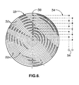
- two or more shapes 37 which can be rectangular, triangular, arcuate, spiral etc., mounted in a pattern on a substrate with the insulated distance "t" defined between end shape.
- Fig. 5 shows such a device using triangular shapes and Fig. 6 with arcuate shapes.
- the shapes/strips are connected via connections 36 in an electrical circuit using a proprietary A.C. bridge circuit or other electric controller.
- the depth when flowing down the inside of the casing 24 may vary from place to place, with local disturbances in the liquid being created by irregularities in liquid discharge, windage, vibration, etc.
- a transducer covering too small an area would then give a misleading local value of conductance rather than the required mean or average reading required for liquid depth measurement.
- the active area of the transducer is set to cover several irregularities so that the conductance measured is the mean value.
- a rectangular or irregular shaped transducer is used with it's narrow width set circumferentially in the inside of the casing and it's long side set at or near vertical - extending lengthwise over a sufficient portion of the casing height to cover any liquid flow irregularities down the casing.
- An alternative arrangement of a serries of small transducers set one above the other and connected in parallel over an area similar to that of the single rectangular transducer would also give the mean conductance value.
- a rectangular transducer would be set with it's long side, as a circumferential arc, around the inside of the casing - extending over a sufficient portion of the casing circumference to cover any liquid flow irregularities and with it's narrow side set at or near horizontal.
- an alternative arrangement with a series of small transducers in the form of an arc and connected in parallel over an area similar to that of the single rectangular transducer would also give the mean conductance value.
- the controller measures the voltage V applied to and current A passing through the liquid flowing down the casing and over the surface of the transducer, with facilities to preset the levels and ranges at which the bridge/electronic circuit operates and gives output signals to control contaminant or liquid flow.
- the value of A/V may be used in Classes X and Y situations to measure and control the degree of contamination of the liquid flowing over the transducer as the electric conductance A/V measured at the transducer corresponds to an equivalent contamination level.
- the value of A/V may be used to measure and control the depth of liquid of constant conductivity flowing over a suitably dimensioned transducer (Class Z).
- a suitably dimensioned transducer Class Z
- An example of a process in which depth measured is advantageous is the termination of liquid flow from a centrifuge. At the accepted minimum flow, the reduction in centrifuge utilisation in continuing the process cycle is greater than the advantage of further liquid separation. At this point, the transducer A/V depth signal proportional to the flow of liquid in the machine casing, signals the end of the centrifuge cycle.
- Class Z is the centrifugal separation of water from fabrics.
- the transducer dimensions, and particularly the spacing "t" between the electrodes, is matched to the application. Generally, the spacing will be closer when used for Classes X and Y and wider for Class Z.
- a small auxiliary wash pipe (38) may be fitted in the casing to clean the surface of the transducer and to recalibrate is as necessary. If the process temperature varies, a temperature sensing device is fitted to measure the wash liquid temperature and, if required, apply a signal to the bridge/electronic controller to adjust the preset conductance levels.
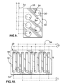
- the transducer device uses strips or shapes that have non-parallel sides so that the insulating substrates separating adjacent strips or shapes are tapered or curved, examples of which are shown in Figs. 7, 8 and 9. This increases the range over which "d/t" is near linear as shown by line “g.h.” on Graph C (Fig. 13) which compares the Graph B parallel electrode results with angled electrodes to increase the control range for some Class Z applications.
- connections from the transducer to the electronic controller may be readjustable externally at the centrifuge to allow the increase/decrease in the amount of electrically insulating material (i.e., alter the values of "t") which has an effect upon the electronic controller's output, as generally indicated in Fig. 10 which shows alternative connections for operating at electrode spacings of "t" and "T".
- Graph A of Fig. 11 shows a typical relationship between the conductivity of the wash liquid and the level of contaminates (organic salts, chloride salts, and other solids conducive in a solution) in the wash liquid.
- Graph C of Fig. 13 demonstrates that it is possible to increase the control range for some applications by implementing electrodes which have nonparallel sides such that the insulating substrate separating adjacent strips or shapes are tapered or curved (examples of which are shown in Figs. 7, 8 and 9).
- the range over which "d/t" is near linear as shown by line gh compares favourably with the results taken from Graph B where the electrodes are parallel, hence demonstrating the increase in the control range for Class Z applications.
- the present invention used as described above, in one form makes a near instantaneous measure of the condition of solids rotating in a centrifuge and, when the required condition is reached, signals the process to proceed without overwashing losses and without delay.
- the apparatus signals the optimum minimum level of liquid flow from a centrifuge for the process to proceed immediately. Both forms compensate automatically for changing process parameters, avoiding the need for manual intervention to adjust for process parameter changes.
- an apparatus in accordance with the invention can be free of the limitations inherent in the state of the art methods of overwashing and applies to all methods of using the transducer as described herein to control liquid flows.
Landscapes
- Centrifugal Separators (AREA)
Abstract
Description
A voltage is applied across the electrodes of the transducer establishing an electric current through any liquid flowing down the casing over the surface of the transducer and hence gaining a measure of the conductance of the wash liquid covering the transducer.
Claims (10)
- An apparatus for the separation of solids and liquids comprising a perforated rotary basket (10) arranged for rotation within a fixed outer casing (16), a washing liquid supply means (22) for providing washing liquid to the interior of the basket and its contents, and a device (26; 28) for establishing a control signal representative of the state of liquids centrifugally expelled from the basket (10) when such liquids impinge on an inner surface (24) of said fixed outer casing (16).
- An apparatus according to claim 1, wherein said device comprises one or more transducers (26; 28) for monitoring the conductance of liquids in the outer casing (16).
- An apparatus according to claim 2, wherein the device comprises a transducer (26; 28) in or on the inner wall surface (24) of the outer casing.
- An apparatus according to claim 3, wherein said inner wall surface (24) of the outer casing is cylindrical and said transducer (26; 28) in or on said inner wall surface (24) is itself part or fully cylindrical.
- An apparatus according to claim 2, wherein the transducer (28) comprises at least two electrodes set in an electrically insulating material.
- An apparatus according to claim 2, 3, 4 or 5, wherein the transducer (28) comprises electrodes (30) coupled to an AC bridge or other form of electronic controller.
- An apparatus according to any of claims 2 to 6, wherein the transducer (28) comprises electrodes (30) which have no adjacent parallel sides whereby to increase the range for which the proportional relationship between the conductance measured via the transducer and the depth of the liquid flowing over the transducer is increased.
- An apparatus according to claim 7, wherein the connections from the transducer to the AC bridge or the electronic controller are readjustable externally to allow the effective increase or decrease in the amount of electrically insulating material between the electrodes.
- An apparatus according to any of claims 1 to 8, comprising an auxiliary wash pipe (38) for cleaning the surfaces of the transducer and to facilitate calibrations.
- An apparatus according to any of claims 1 to 9, including a temperature sensing device to measure the temperature of the liquid and send a signal to adjust the generated output accordingly.
Applications Claiming Priority (2)
| Application Number | Priority Date | Filing Date | Title |
|---|---|---|---|
| GB0222853 | 2002-10-03 | ||
| GB0222853A GB2393672A (en) | 2002-10-03 | 2002-10-03 | Automatic control of wash liquor in basket centrifuge |
Publications (2)
| Publication Number | Publication Date |
|---|---|
| EP1405674A2 true EP1405674A2 (en) | 2004-04-07 |
| EP1405674A3 EP1405674A3 (en) | 2005-10-19 |
Family
ID=9945176
Family Applications (1)
| Application Number | Title | Priority Date | Filing Date |
|---|---|---|---|
| EP03255526A Withdrawn EP1405674A3 (en) | 2002-10-03 | 2003-09-04 | Improvements in the control and classification of liquids in separating processes |
Country Status (3)
| Country | Link |
|---|---|
| US (1) | US7229549B2 (en) |
| EP (1) | EP1405674A3 (en) |
| GB (1) | GB2393672A (en) |
Cited By (2)
| Publication number | Priority date | Publication date | Assignee | Title |
|---|---|---|---|---|
| WO2013135774A1 (en) * | 2012-03-14 | 2013-09-19 | Bma Braunschweigische Maschinenbauanstalt Ag | Device having a discontinuously operating centrifuge for separating syrup from massecuites and method for operating such a device |
| EP3722004A1 (en) | 2019-03-18 | 2020-10-14 | BMA Braunschweigische Maschinenbauanstalt AG | Method for controlling the operation of a continuously or periodically operating centrifuge and device for carrying out the method |
Families Citing this family (2)
| Publication number | Priority date | Publication date | Assignee | Title |
|---|---|---|---|---|
| US7763177B2 (en) * | 2006-10-26 | 2010-07-27 | Atlantium Technologies Ltd. | System and method for ultrasonic cleaning of ultraviolet disinfection system |
| US10814338B2 (en) | 2017-08-09 | 2020-10-27 | Delta Separations, Llc | Device, system and methods for separation and purification of organic compounds from botanical material |
Family Cites Families (11)
| Publication number | Priority date | Publication date | Assignee | Title |
|---|---|---|---|---|
| GB538444A (en) * | 1939-02-25 | 1941-08-05 | August Henry Schutte | Improvements in or relating to continuously acting centrifugal filters |
| US2646172A (en) * | 1947-09-19 | 1953-07-21 | Baker Perkins Inc | Centrifugal separator |
| BE519836A (en) * | 1952-05-19 | |||
| FR1125370A (en) * | 1954-07-06 | 1956-10-30 | Western States Machine Co | Centrifuge improvements |
| SU518234A1 (en) | 1974-10-17 | 1976-06-25 | Грозненский Филиал Научно-Исследовательского И Проектного Института По Комплексной Автоматизации В Нефтяной И Химической Промышленности | Device for automatic control of a centrifugal separator of continuous cyclic action |
| US4229298A (en) * | 1979-02-05 | 1980-10-21 | The Western States Machine Company | Method and apparatus for determining the thickness of a charge wall formed in a centrifugal basket |
| SE8006732L (en) * | 1980-09-26 | 1982-03-27 | Alfa Laval Ab | DEVICE FOR MONITORING SEPARATED SEDIMENT THROUGH THROUGH THE NOZZLE OF A CENTRIFUGAL Separator |
| DE3925198A1 (en) * | 1988-09-01 | 1990-03-15 | Krauss Maffei Ag | Monitoring successive stages of centrifugal slurry filtration - by vibration sensor mounted on arm pivoting towards sieve surface |
| WO1997020634A1 (en) * | 1995-12-01 | 1997-06-12 | Baker Hughes Incorporated | Method and apparatus for controlling and monitoring continuous feed centrifuge |
| US6063292A (en) * | 1997-07-18 | 2000-05-16 | Baker Hughes Incorporated | Method and apparatus for controlling vertical and horizontal basket centrifuges |
| US6213928B1 (en) * | 1999-08-17 | 2001-04-10 | Shrinivas G. Joshi | Method and apparatus for measuring the thickness of sludge deposited on the sidewall of a centrifuge |
-
2002
- 2002-10-03 GB GB0222853A patent/GB2393672A/en not_active Withdrawn
-
2003
- 2003-09-04 EP EP03255526A patent/EP1405674A3/en not_active Withdrawn
- 2003-09-30 US US10/676,960 patent/US7229549B2/en not_active Expired - Lifetime
Cited By (8)
| Publication number | Priority date | Publication date | Assignee | Title |
|---|---|---|---|---|
| WO2013135774A1 (en) * | 2012-03-14 | 2013-09-19 | Bma Braunschweigische Maschinenbauanstalt Ag | Device having a discontinuously operating centrifuge for separating syrup from massecuites and method for operating such a device |
| CN103717311A (en) * | 2012-03-14 | 2014-04-09 | Bma布伦瑞克机器制造有限公司 | Device having discontinuously operating centrifuge for separating syrup from massecuites and method for operating such device |
| US20150290662A1 (en) * | 2012-03-14 | 2015-10-15 | Bma Braunschweigische Maschinenbauanstalt Ag | Device having a discontinuously operating centrifuge for separating syrup from sugar massecuites and method for operating such a device |
| RU2586153C2 (en) * | 2012-03-14 | 2016-06-10 | Бма Брауншвайгише Машиненбауанштальт Аг | Device for separation of syrup from sugar fillmass containing centrifuge of periodic action, and method of using said device |
| CN103717311B (en) * | 2012-03-14 | 2016-10-19 | Bma布伦瑞克机器制造有限公司 | There is the equipment of the centrifuge of the discontinuous operation for syrup separation from massecuite and for the method running this equipment |
| US10549288B2 (en) | 2012-03-14 | 2020-02-04 | Bma Braunschweigische Maschinenbauanstalt Ag | Device having a discontinuously operating centrifuge for separating syrup from sugar massecuites and method for operating such a device |
| EP3722004A1 (en) | 2019-03-18 | 2020-10-14 | BMA Braunschweigische Maschinenbauanstalt AG | Method for controlling the operation of a continuously or periodically operating centrifuge and device for carrying out the method |
| US11697854B2 (en) | 2019-03-18 | 2023-07-11 | Bma Braunschweigische Maschinenbauanstalt Ag | Method for controlling the operation of a continuously or periodically operating centrifuge and device for conducting the method |
Also Published As
| Publication number | Publication date |
|---|---|
| GB0222853D0 (en) | 2002-11-06 |
| EP1405674A3 (en) | 2005-10-19 |
| US7229549B2 (en) | 2007-06-12 |
| US20040065603A1 (en) | 2004-04-08 |
| GB2393672A (en) | 2004-04-07 |
Similar Documents
| Publication | Publication Date | Title |
|---|---|---|
| US20100213953A1 (en) | Methods and apparatus relating to fluidised beds | |
| US7540837B2 (en) | Systems for centrifuge control in response to viscosity and density parameters of drilling fluids | |
| JP2019162603A (en) | Coagulant addition amount control device, sludge concentration system and coagulant addition amount control method | |
| US7229549B2 (en) | Control and classification of liquids in separating processes | |
| NO343295B1 (en) | Beach detection sensors for vibratory separator | |
| JP3731292B2 (en) | Operation control method of sludge centrifugal dehydrator | |
| WO2008153267A1 (en) | Regenerating process and regenerating system to regenerate waste slurry from semiconductor wafer manufacturing process | |
| CN107073485A (en) | For the method for the operation for monitoring and/or adjusting centrifuge | |
| CN116351581B (en) | High-efficient horizontal spiral filter centrifuge of unloading | |
| JP2013158749A (en) | Concentration/dehydration device | |
| JP2004074066A (en) | Rotary pressure dehydrator having control means | |
| CN1203315C (en) | Moisture sensor | |
| JP4487242B2 (en) | Rotary concentrator controller | |
| EP2176553A1 (en) | Method of and apparatus for controlling the height of a column of material in a vessel upstream of a pump | |
| JP4824539B2 (en) | Sludge concentration control device | |
| JP2003075429A (en) | Scum detection method and device | |
| JP3006871B2 (en) | Sludge dewatering operation control device for screw decanter centrifuge | |
| JP2005507311A (en) | Device for measuring the residual liquid content of solid cake in a centrifuge | |
| CN213679934U (en) | Sewage treatment equipment | |
| JP3547685B2 (en) | Centrifuge | |
| WO2007083508A1 (en) | Belt type thickening machine | |
| JPH11319415A (en) | Coagulator | |
| JP2000018821A (en) | Dehydration drying equipment | |
| JPH1167712A (en) | Chemical treatment apparatus and flow control method thereof | |
| NL8001806A (en) | METHOD AND APPARATUS FOR CONTROLLING THE DISPOSITION OF SOLIDS IN LIQUID. |
Legal Events
| Date | Code | Title | Description |
|---|---|---|---|
| PUAI | Public reference made under article 153(3) epc to a published international application that has entered the european phase |
Free format text: ORIGINAL CODE: 0009012 |
|
| AK | Designated contracting states |
Kind code of ref document: A2 Designated state(s): AT BE BG CH CY CZ DE DK EE ES FI FR GB GR HU IE IT LI LU MC NL PT RO SE SI SK TR |
|
| AX | Request for extension of the european patent |
Extension state: AL LT LV MK |
|
| PUAL | Search report despatched |
Free format text: ORIGINAL CODE: 0009013 |
|
| AK | Designated contracting states |
Kind code of ref document: A3 Designated state(s): AT BE BG CH CY CZ DE DK EE ES FI FR GB GR HU IE IT LI LU MC NL PT RO SE SI SK TR |
|
| AX | Request for extension of the european patent |
Extension state: AL LT LV MK |
|
| RIC1 | Information provided on ipc code assigned before grant |
Ipc: 7B 04B 11/04 B Ipc: 7B 04B 15/12 A |
|
| 17P | Request for examination filed |
Effective date: 20060413 |
|
| AKX | Designation fees paid |
Designated state(s): AT BE BG CH CY CZ DE DK EE ES FI FR GB GR HU IE IT LI LU MC NL PT RO SE SI SK TR |
|
| 17Q | First examination report despatched |
Effective date: 20071109 |
|
| GRAP | Despatch of communication of intention to grant a patent |
Free format text: ORIGINAL CODE: EPIDOSNIGR1 |
|
| STAA | Information on the status of an ep patent application or granted ep patent |
Free format text: STATUS: THE APPLICATION IS DEEMED TO BE WITHDRAWN |
|
| 18D | Application deemed to be withdrawn |
Effective date: 20090103 |