EP1407546B1 - Filtre réactance à pente de flanc améliorée - Google Patents
Filtre réactance à pente de flanc améliorée Download PDFInfo
- Publication number
- EP1407546B1 EP1407546B1 EP02737839A EP02737839A EP1407546B1 EP 1407546 B1 EP1407546 B1 EP 1407546B1 EP 02737839 A EP02737839 A EP 02737839A EP 02737839 A EP02737839 A EP 02737839A EP 1407546 B1 EP1407546 B1 EP 1407546B1
- Authority
- EP
- European Patent Office
- Prior art keywords
- resonator
- branch
- resonators
- reactance filter
- filter according
- Prior art date
- Legal status (The legal status is an assumption and is not a legal conclusion. Google has not performed a legal analysis and makes no representation as to the accuracy of the status listed.)
- Expired - Lifetime
Links
- 238000010168 coupling process Methods 0.000 claims description 33
- 238000005859 coupling reaction Methods 0.000 claims description 33
- 230000008878 coupling Effects 0.000 claims description 32
- 239000000463 material Substances 0.000 claims description 24
- 230000003068 static effect Effects 0.000 claims description 18
- 239000007772 electrode material Substances 0.000 claims description 14
- 238000000034 method Methods 0.000 claims description 3
- 230000005540 biological transmission Effects 0.000 description 12
- WFKWXMTUELFFGS-UHFFFAOYSA-N tungsten Chemical compound [W] WFKWXMTUELFFGS-UHFFFAOYSA-N 0.000 description 8
- 229910052782 aluminium Inorganic materials 0.000 description 7
- XAGFODPZIPBFFR-UHFFFAOYSA-N aluminium Chemical compound [Al] XAGFODPZIPBFFR-UHFFFAOYSA-N 0.000 description 7
- 229910052721 tungsten Inorganic materials 0.000 description 6
- 239000010937 tungsten Substances 0.000 description 6
- XLOMVQKBTHCTTD-UHFFFAOYSA-N Zinc monoxide Chemical compound [Zn]=O XLOMVQKBTHCTTD-UHFFFAOYSA-N 0.000 description 4
- VYPSYNLAJGMNEJ-UHFFFAOYSA-N Silicium dioxide Chemical compound O=[Si]=O VYPSYNLAJGMNEJ-UHFFFAOYSA-N 0.000 description 3
- PMHQVHHXPFUNSP-UHFFFAOYSA-M copper(1+);methylsulfanylmethane;bromide Chemical compound Br[Cu].CSC PMHQVHHXPFUNSP-UHFFFAOYSA-M 0.000 description 3
- 238000010586 diagram Methods 0.000 description 3
- 239000000758 substrate Substances 0.000 description 3
- PIGFYZPCRLYGLF-UHFFFAOYSA-N Aluminum nitride Chemical compound [Al]#N PIGFYZPCRLYGLF-UHFFFAOYSA-N 0.000 description 2
- 239000004411 aluminium Substances 0.000 description 2
- 238000013016 damping Methods 0.000 description 2
- 230000001629 suppression Effects 0.000 description 2
- 239000011787 zinc oxide Substances 0.000 description 2
- IRLPACMLTUPBCL-KQYNXXCUSA-N 5'-adenylyl sulfate Chemical compound C1=NC=2C(N)=NC=NC=2N1[C@@H]1O[C@H](COP(O)(=O)OS(O)(=O)=O)[C@@H](O)[C@H]1O IRLPACMLTUPBCL-KQYNXXCUSA-N 0.000 description 1
- 230000006978 adaptation Effects 0.000 description 1
- 230000008033 biological extinction Effects 0.000 description 1
- 238000010276 construction Methods 0.000 description 1
- 230000007423 decrease Effects 0.000 description 1
- 230000000694 effects Effects 0.000 description 1
- 230000005684 electric field Effects 0.000 description 1
- 229910052751 metal Inorganic materials 0.000 description 1
- 239000002184 metal Substances 0.000 description 1
- 230000000737 periodic effect Effects 0.000 description 1
- 238000000926 separation method Methods 0.000 description 1
- 235000012239 silicon dioxide Nutrition 0.000 description 1
- 239000000377 silicon dioxide Substances 0.000 description 1
- 229910052814 silicon oxide Inorganic materials 0.000 description 1
- 239000010409 thin film Substances 0.000 description 1
Images


Classifications
-
- H—ELECTRICITY
- H03—ELECTRONIC CIRCUITRY
- H03H—IMPEDANCE NETWORKS, e.g. RESONANT CIRCUITS; RESONATORS
- H03H9/00—Networks comprising electromechanical or electro-acoustic elements; Electromechanical resonators
- H03H9/46—Filters
- H03H9/54—Filters comprising resonators of piezoelectric or electrostrictive material
- H03H9/58—Multiple crystal filters
- H03H9/60—Electric coupling means therefor
- H03H9/605—Electric coupling means therefor consisting of a ladder configuration
Definitions
- the invention relates to bulk wave filters (bulk acoustic wave filter or BAW filter called), which are constructed according to the Reaktanzfiltertex.
- reactance filters are for example also from the DE 196 38 451 A and the JP 63 253711 A known.
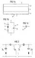
- a BAW resonator R exists according to FIG. 1a in its simplest embodiment of a thin film P of a piezoelectric material, which is provided on the top and bottom each with an electrode E1, E2. Ideally, this structure is surrounded by air on both sides of the electrode.
- an electric field acts on the piezoelectric layer, as a result of which the piezoelectric material converts part of the electrical energy into mechanical energy in the form of acoustic waves. These propagate parallel to the field direction as so-called bulk waves and are reflected at the electrode / air interfaces.
- f r which depends on the thickness of the piezoelectric layer or on the thickness of the volume oscillator, the resonator shows a resonance and thus behaves like an electrical resonator.
- the BAW resonator R consists of a series resonance circuit of dynamic inductance L1, dynamic capacitance C1 and a dynamic resistance R1, as well as a static connected in parallel thereto Capacitance C0 of the BAW resonator.
- the series resonance circuit reproduces the behavior of the resonator in the case of resonance, ie in the region of the resonance frequency f r .
- the static capacitance C0 reflects the behavior in the range f «f r and f r » f.
- the dynamic capacitance C1 is proportional to the static capacitance C0 of the BAW resonator.
- a reactance filter is made according to FIG. 7 of at least one basic element which has a series-connected resonator R2 with a resonant frequency f rs and associated antiresonant frequency f as and a second resonator R1 connected in parallel with a second terminal, in particular parallel to the ground, with a resonant frequency f rp and associated antiresonant frequency f ap .
- a filter with bandpass behavior and a center frequency f 0 the following relationship applies to the two resonators in the serial or parallel branch: f ap ⁇ f rs ⁇ f 0
- FIG. 16a shows the course of the impedance Zs of the serial resonator and the admittance Yp of the parallel resonator over the frequency f.
- FIG. 16b shows the transmission behavior of a filter consisting of a basic element, the resonance frequencies of which FIG. 16a are selected.
- FIG. 7 shows a basic member, in principle as a two-port with the terminals 3 - 1 and 3 - 2 (Tor 1) and the terminals 3 - 3 and 3, respectively - 4 of Tor 2 is to be considered.
- the connection 3 - 1 is the input and the connection 3 - 3 the output of the series resonator.
- the input of the parallel resonator is connected to the connection 3 - 1.
- the terminals 3 - 2 and 3 - 4 represent the reference ground in an asymmetrical operation.
- the output of the parallel resonator 3 - 5, which faces the reference ground, is hereinafter referred to as the output or ground side of the parallel resonator.
- the inductance L ser which lies between the output side of the parallel resonator and the reference ground, reflects the connection to the housing ground in the real structure again.
- Resonators of the same type (series resonator or parallel resonator) arranged directly one after the other in a circuit of a reactance filter can also be combined to form a resonator, the overall capacitive effect of the combined resonator remaining the same.
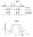
- the curve 1 in FIG. 6 shows the transmission behavior of a reactance filter, which is composed of uniform BAW resonators, each having a relatively large ratio of dynamic to static capacity. The individual resonators therefore have a relatively large bandwidth.
- Curve 2 is the transmission curve of a corresponding reactance filter of resonators with a small ratio of dynamic to static capacitance and therefore relatively low bandwidth of the single resonators. In the first case (curve 1) one obtains a bandpass filter with high bandwidth and low edge steepness, in the second case (curve 2) one obtains a bandpass filter with lower bandwidth and high edge steepness.
- a further possibility for broadening a steep-edged filter consists in a reduction of the ratio (C 0p / C 0s ) of static capacitance C0 p in the parallel branch and static capacitance C0s in the series branch.
- the bandwidth can be increased to some extent without losing the self-adaptation and the associated low losses.
- the selection level of the BAW reactance filter is greatly reduced, so that the filter can no longer fulfill possible selection requirements and, for example, can no longer adequately damp unwanted frequencies.
- the invention takes advantage of this and indicates a reactance filter constructed of BAW-type resonators. It comprises at least one basic element with a first resonator in a first branch and a second resonator in a second one Branch, which are connected in parallel with each other, wherein one of the branches is the serial branch, while the other branch is a parallel branch.
- the reactance filter according to the invention has a transmission behavior with an improved because steeper edge.
- the other edge and the other resonator and filter properties remain unaffected. If, for example, in the case of a resonator in the serial branch, the ratio V c is reduced compared with the corresponding ratio V c in the resonator of the parallel branch, the right flank of the passband is set steeper, that is to say the flank delimiting the passband from higher frequencies.
- a passband having a steeper left slope is obtained.
- the right edge of the passband is determined by the characteristics of the serial resonator.
- the steepness of the right flank can be seen from how quickly the impedance curve of the serial resonator increases from the resonant frequency to the anti-resonant frequency.
- a steeper impedance increase in a (serial) resonator is obtained when the distance between resonant and anti-resonant frequencies of the resonator is reduced.
- a reactance filter Since a real reactance filter is generally obtained by connecting a plurality of base elements, a reactance filter usually has a plurality of series resonators and a plurality of parallel resonators.
- a reactance filter according to the invention is already obtained when said changes are made in a single resonator of one type (serial or parallel).
- a further improved even steeper edge is obtained if a plurality of resonators of one type, preferably all resonators of one type have a smaller distance between resonant and anti-resonant frequencies. Due to the given dependence of the corresponding quantities on each other, this distance increases with the said ratio V c of the dynamic to the static capacity.
- a resonator having such a reduced pitch will be referred to as a narrow band resonator hereinafter.
- a resonator with a correspondingly greater distance from the resonance and anti-resonance frequency is referred to as a broadband resonator.
- the broadbandity of the filter that is, the width of the passband is achieved regardless of the use of at least one narrow-band resonator for a first branch characterized in that broadband resonators are used in the second branch.
- a filter according to the invention having, for example, an improved steeper left flank is achieved by narrow-band parallel resonators which as a result achieve a high selection at frequencies which are slightly lower than the lowest frequency of the pass band of the filter.
- filters are preferably used as filters in the receive path of the current GSM or CDMA-based mobile radio systems, which must provide a high suppression of the transmission band.
- K 2 eff ⁇ / 2 2 x fa - Fri. fa
- K 2 eff ⁇ / 2 2 x fa - Fri. fa
- a narrow band resonator can be realized on a suitable piezoelectric material with a lower effective electromechanical coupling coefficient.
- This effective electromechanical coupling coefficient is obtained from the sum of the effective couplings of all the modes propagatable in a piezoelectric material.
- the effective coupling (for the used mode) can be determined from the equivalent circuit diagram of a BAW resonator according to the following formula: k 2 eff ⁇ C ⁇ 1 C 1 + C 0
- a reactance filter according to the invention therefore has, for example, resonators with a higher coupling piezo material in the series branch of the reactance filter, whereas resonators with lower coupling piezo material have the same branch in the same branch.
- Such a filter then has a high steepness of the left flank.
- the reactance filter according to the invention retains a high bandwidth, which is ensured by the relatively high separation of resonance frequencies and anti-resonance frequency in the series resonators.
- the effective coupling can also be reduced in a reactance filter with BAW resonators by inserting an additional layer of non-piezoelectric material between the two electrodes of a BAW resonator.
- the coupling coefficient is thereby reduced by the proportion which the layer of the non-piezoelectric material has at the ratio of the layer thickness of the non-piezoelectric material to the total layer thickness of the resonator.
- a reduction of the effective coupling is obtained, which for the filter or the resonator is equivalent to a reduction of the ratio V c and thus also equivalent to a reduction the distance of resonance and anti-resonant frequency is.
- a reactance filter according to the invention therefore has, for example, resonators which use in a first branch an electrode material which differs from the electrode material of the resonators in the second branch.
- a reactance filter with resonators with tungsten electrodes in a first branch and resonators with aluminum electrodes in a second branch accordingly has a narrowband resonator in the second branch. If the second branch is a parallel branch, the left edge of the passband of the reactance filter is improved. If the corresponding narrowband resonator is used in the serial branch, the right flank is improved in the reactance filter.
- a BAW resonator is preferably surrounded by air on both sides of the electrodes.
- two contact points far away from one another are provided for an electrode layer, this being referred to as so-called bridge resonators.
- the acoustic wave is reflected on both sides of the resonator at the solid-air interface. It is also possible, however, one BAW resonator in such a way that one of the electrodes over the entire surface rests on a substrate.
- the reflection of the acoustic wave can then be ensured with an acoustic mirror, which can be realized for example by two layers of different acoustic impedance, each having a layer thickness of ⁇ / 4 with respect to the wavelength ⁇ of the acoustic wave within the layer material.
- the repeated reflections at the junctions of two layers with very different acoustic impedances then lead to extinction of the wave components reflected at different boundary surfaces, which in turn means a high reflection for the mirror.
- a reactance filter according to the invention therefore has Bridgeresonators, for example, in the parallel branch, whereas resonators with an acoustic mirror are provided in the serial branch, wherein a transmission characteristic with a passband steeper in the right flank is obtained.
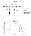
- FIG. 7 shows a basic element which is constructed from a first resonator R1 in a parallel branch and a second resonator R2 in a serial branch. Ports 3-1 and 3-2 form the filter input, ports 3-3 and 3-4 the filter output.
- the parallel branch or the resonator R1 in the parallel branch is connected via a series inductance L ser , formed from the sum of the inductances of the terminal to the housing ground, to the terminals 3-2 and 3-4 respectively.
- the resonator is formed R1 with a piezoelectric layer of zinc oxide having an electromechanical coupling constant K 2 eff 1 and the resonator R2 with a piezoelectric layer p of aluminum nitride having a piezoelectric coupling constant K 2 eff 2 in this embodiment, where K 2 eff 1> K 2 eff 2.
- K 2 eff 1> K 2 eff 2 the resonance frequencies and thus also the Antiresonanzfrequenzen the two resonators R1 and R2 are adjusted so that the resonance frequency of R2 is approximately equal to the anti-resonant frequency of R1.
- the transmission curve 2 in FIG. 10 shows the damping behavior of a reactance filter according to the invention according to this embodiment, which is compared with the transmission curve 1 of a conventional reactance filter, in which both resonators use zinc oxide for the piezoelectric layer p of the resonators. It turns out that the right flank of the curve 2 is set much steeper than that of the known filter. The bandwidth of the overall filter is only marginally reduced.
- FIG. 12 shows the influence of the electrode material on the impedance behavior of a resonator.
- Curves 3 and 4 show the impedance behavior according to FIG. 1 formed resonator, wherein curve 3 represents the impedance of a resonator with aluminum electrodes, the curve 4, however, the impedance behavior of a resonator with tungsten electrodes. It can be seen that the greater effective coupling of tungsten electrodes according to curve 4 results in a higher distance of the resonant frequency from the anti-resonant frequency.
- FIG. 15 shows a resonator, which is arranged with the aid of an acoustic mirror AS on a substrate S.
- a reactance filter according to the invention will now consist of at least one basic element (for example according to FIG. 7 ), wherein in a first branch resonators in Bridgebau way, in a second branch, however, resonators are used with acoustic mirror. Since the effective coupling coefficient for resonators according to FIG. 14 is greater than resonators according to FIG. 15 , the flank of the passband which is associated with the armature with the acoustic mirrors can be made steeper. For example, if the resonators R1 are implemented with acoustic mirrors, the resonators R2 as Bridgeresonatoren, a steeper left flank is obtained in the transmission behavior of the reactance filter thus constructed.
Landscapes
- Chemical & Material Sciences (AREA)
- Crystallography & Structural Chemistry (AREA)
- Physics & Mathematics (AREA)
- Acoustics & Sound (AREA)
- Piezo-Electric Or Mechanical Vibrators, Or Delay Or Filter Circuits (AREA)
Claims (14)
- Filtre à réactance constitué de résonateurs du type BAW,- comprenant au moins un élément de base ayant un premier résonateur dans une première branche et un deuxième résonateur dans une deuxième branche, l'une des branches étant une branche série et l'autre branche une branche parallèle,- dans lequel chaque résonateur a un rapport VC = C1/CO de la capacité dynamique à la capacité statique,caractérisé en ce que le rapport VC du résonateur de la deuxième branche est réglée d'une manière à être plus petite que celui du résonateur de la première branche.
- Filtre à réactance suivant la revendication 1,- dans lequel le résonateur de la première branche est en un premier matériau piézo-électrique et le résonateur de la deuxième branche est en en un deuxième matériau piézo-électrique qui en diffère, et- dans lequel le coefficient de couplage du premier matériau est plus grand que celui du deuxième matériau piézo-électrique.
- Filtre à réactance suivant la revendication 1 ou 2,
dans lequel les matériaux d'électrode des résonateurs de la première et de la deuxième branches sont différents, le matériau d'électrode des résonateurs de la première branche produisant un couplage efficace plus grand que le matériau d'électrode des résonateurs de la deuxième branche. - Filtre à réactance suivant l'une des revendications 1 à 3,
dans lequel les résonateurs de la deuxième branche comprennent des résonateurs BAW dans lesquels il est prévu entre deux électrodes, outre une couche d'un matériau piézo-électrique, encore une couche d'un autre matériau qui a une constante diélectrique plus petite que le matériau piézo-électrique. - Filtre à réactance suivant l'une des revendications 1 à 4,
dans lequel le coefficient de couplage efficace des résonateurs de la deuxième branche est abaissé en utilisant un miroir acoustique en dessous d'une couche d'électrode par rapport au coefficient de couplage des résonateurs de la première branche. - Filtre à réactance suivant la revendication 5,
dans lequel les résonateurs de la première et de la deuxième branches ont des miroirs acoustiques qui, en ce qui concerne les épaisseurs des couches de miroir et/ou les propriétés de réflexion, sont différents dans les deux branches. - Filtre à réactance suivant la revendication 5,
dans lequel seuls les résonateurs de la deuxième branche ont un miroir acoustique et dans lequel des résonateurs de la première branche utilisent un autre procédé de réflexion des ondes acoustiques. - Filtre à réactance suivant l'une des revendications 1 à 7,
comprenant plusieurs éléments de base câblés entre eux, les branches en série des éléments de base étant montées en série les une avec les autres, tandis que les branches en parallèle le sont en parallèle. - Filtre à réactance suivant la revendication 8,
dans lequel le rapport VC = C1/CO de la capacité dynamique à la capacité statique d'au moins un résonateur de la branche série est ajusté à une valeur autre que le rapport correspondant des résonateurs dans les branches parallèles. - Filtre à réactance suivant l'une des revendications 1 à 9,
ayant un comportement à la transmission ayant une bande passante ayant un front gauche plus abrupt, dans lequel le rapport VC = C1/CO de la capacité dynamique à la capacité statique est abaissé dans au moins un résonateur des branches parallèles par rapport aux résonateurs de la branche série. - Filtre à réactance suivant l'une des revendications 1 à 9,
ayant un comportement à la transmission ayant une bande passante ayant un front droit plus abrupt, dans lequel le rapport VC = C1/CO de la capacité dynamique à la capacité statique est abaissé dans au moins un résonateur de la branche série par rapport aux résonateurs des branches parallèles. - Filtre à réactance suivant l'une des revendications 1 à 11,
dans lequel les résonateurs des branches parallèles sont montés en série avec une inductance et sont reliés respectivement individuellement à une borne de masse. - Utilisation d'un filtre à réactance suivant l'une des revendications précédentes, dans un système de communication sans fil ayant une section d'émission et une section de réception, dans laquelle on met en oeuvre pour le filtre de la partie d'émission un filtre à réactance ayant un front droit plus abrupt et pour le filtre de la partie de réception un filtre à réactance ayant un front gauche plus abrupt.
- Utilisation d'un filtre à réactance suivant l'une des revendications précédentes, dans un duplexeur ayant deux filtres bande passante, dans laquelle on met en oeuvre, pour le filtre ayant la fréquence médiane la plus basse, un filtre à réactance ayant un front droit plus abrupt et pour le filtre ayant la fréquence médiane la plus haute un filtre à réactance ayant un front gauche plus abrupt.
Applications Claiming Priority (3)
| Application Number | Priority Date | Filing Date | Title |
|---|---|---|---|
| DE10134987 | 2001-07-18 | ||
| DE10134987A DE10134987A1 (de) | 2001-07-18 | 2001-07-18 | Reaktanzfilter mit verbesserter Flankensteilheit |
| PCT/DE2002/001761 WO2003009470A1 (fr) | 2001-07-18 | 2002-05-16 | Filtre à réactance à pente de flanc améliorée |
Publications (2)
| Publication Number | Publication Date |
|---|---|
| EP1407546A1 EP1407546A1 (fr) | 2004-04-14 |
| EP1407546B1 true EP1407546B1 (fr) | 2010-07-07 |
Family
ID=7692245
Family Applications (1)
| Application Number | Title | Priority Date | Filing Date |
|---|---|---|---|
| EP02737839A Expired - Lifetime EP1407546B1 (fr) | 2001-07-18 | 2002-05-16 | Filtre réactance à pente de flanc améliorée |
Country Status (5)
| Country | Link |
|---|---|
| US (1) | US7126253B2 (fr) |
| EP (1) | EP1407546B1 (fr) |
| JP (1) | JP4243537B2 (fr) |
| DE (2) | DE10134987A1 (fr) |
| WO (1) | WO2003009470A1 (fr) |
Cited By (1)
| Publication number | Priority date | Publication date | Assignee | Title |
|---|---|---|---|---|
| US9595939B2 (en) | 2009-03-04 | 2017-03-14 | Epcos Ag | Reactance filter having a steep edge |
Families Citing this family (21)
| Publication number | Priority date | Publication date | Assignee | Title |
|---|---|---|---|---|
| WO2006137275A1 (fr) * | 2005-06-20 | 2006-12-28 | Murata Manufacturing Co., Ltd. | Filtre à film mince piézoélectrique |
| US7598827B2 (en) | 2006-06-19 | 2009-10-06 | Maxim Integrated Products | Harmonic termination of power amplifiers using BAW filter output matching circuits |
| US7586389B2 (en) * | 2006-06-19 | 2009-09-08 | Maxim Integrated Products, Inc. | Impedance transformation and filter using bulk acoustic wave technology |
| JP2008172713A (ja) * | 2007-01-15 | 2008-07-24 | Hitachi Media Electoronics Co Ltd | 圧電薄膜共振器および圧電薄膜共振器フィルタおよびその製造方法 |
| US7646265B2 (en) * | 2007-04-11 | 2010-01-12 | Maxim Integrated Products, Inc. | BAW resonator filter bandwidth and out-of-band frequency rejection |
| JP5237138B2 (ja) | 2009-01-27 | 2013-07-17 | 太陽誘電株式会社 | フィルタ、デュープレクサ、通信モジュール |
| DE102010048965B4 (de) * | 2010-10-20 | 2015-01-22 | Epcos Ag | Bandsperrfilter mit einer Serienverschaltung von zumindest zwei pi-Gliedern |
| US8508316B2 (en) * | 2010-10-21 | 2013-08-13 | Epcos Ag | Bulk acoustic wave filter of ladder-type structure |
| JP5877043B2 (ja) * | 2011-11-22 | 2016-03-02 | 太陽誘電株式会社 | デュプレクサ |
| JP6183932B2 (ja) * | 2013-03-15 | 2017-08-23 | スナップトラック・インコーポレーテッド | 音響波で動作する共鳴器を備えるリアクタンスフィルタ |
| JP6374653B2 (ja) | 2013-11-18 | 2018-08-15 | 太陽誘電株式会社 | 弾性波フィルタ及び分波器 |
| US10581403B2 (en) | 2016-07-11 | 2020-03-03 | Qorvo Us, Inc. | Device having a titanium-alloyed surface |
| US10727809B2 (en) * | 2016-12-15 | 2020-07-28 | Qorvo Us, Inc. | Bulk acoustic wave resonator with multilayer piezoelectric structure |
| US10917072B2 (en) * | 2019-06-24 | 2021-02-09 | Resonant Inc. | Split ladder acoustic wave filters |
| US10547281B1 (en) * | 2018-07-13 | 2020-01-28 | Qualcomm Incorporated | Source impedance tuning circuit for a receive path |
| US11757430B2 (en) | 2020-01-07 | 2023-09-12 | Qorvo Us, Inc. | Acoustic filter circuit for noise suppression outside resonance frequency |
| US20220045664A1 (en) * | 2020-08-10 | 2022-02-10 | RF360 Europe GmbH | Radio frequency (rf) filter with increased shunt resonator coupling coefficient |
| US11632097B2 (en) | 2020-11-04 | 2023-04-18 | Qorvo Us, Inc. | Coupled resonator filter device |
| US11575363B2 (en) * | 2021-01-19 | 2023-02-07 | Qorvo Us, Inc. | Hybrid bulk acoustic wave filter |
| US12170515B2 (en) | 2022-01-31 | 2024-12-17 | Qorvo Us, Inc. | Reversed semilattice filter |
| US12587172B2 (en) | 2023-03-15 | 2026-03-24 | Qorvo Us, Inc. | Pin reconfigurable baw filters |
Family Cites Families (4)
| Publication number | Priority date | Publication date | Assignee | Title |
|---|---|---|---|---|
| JPS55127720A (en) * | 1979-03-27 | 1980-10-02 | Tohoku Metal Ind Ltd | Ladder-type ceramic filter |
| JPS55127719A (en) * | 1979-03-27 | 1980-10-02 | Tohoku Metal Ind Ltd | Ladder-type ceramic filter |
| JPS63253711A (ja) * | 1987-04-09 | 1988-10-20 | Kyocera Corp | 梯子型圧電フイルタ |
| DE19638451A1 (de) | 1996-09-19 | 1998-04-02 | Siemens Matsushita Components | Reaktanzfilter mit OFW-Resonatoren |
-
2001
- 2001-07-18 DE DE10134987A patent/DE10134987A1/de not_active Ceased
-
2002
- 2002-05-16 EP EP02737839A patent/EP1407546B1/fr not_active Expired - Lifetime
- 2002-05-16 WO PCT/DE2002/001761 patent/WO2003009470A1/fr not_active Ceased
- 2002-05-16 JP JP2003514696A patent/JP4243537B2/ja not_active Expired - Fee Related
- 2002-05-16 DE DE50214525T patent/DE50214525D1/de not_active Expired - Lifetime
- 2002-05-16 US US10/483,928 patent/US7126253B2/en not_active Expired - Lifetime
Cited By (1)
| Publication number | Priority date | Publication date | Assignee | Title |
|---|---|---|---|---|
| US9595939B2 (en) | 2009-03-04 | 2017-03-14 | Epcos Ag | Reactance filter having a steep edge |
Also Published As
| Publication number | Publication date |
|---|---|
| JP4243537B2 (ja) | 2009-03-25 |
| WO2003009470A1 (fr) | 2003-01-30 |
| DE10134987A1 (de) | 2003-02-06 |
| JP2004535738A (ja) | 2004-11-25 |
| US7126253B2 (en) | 2006-10-24 |
| EP1407546A1 (fr) | 2004-04-14 |
| US20040263286A1 (en) | 2004-12-30 |
| DE50214525D1 (de) | 2010-08-19 |
Similar Documents
| Publication | Publication Date | Title |
|---|---|---|
| EP1407546B1 (fr) | Filtre réactance à pente de flanc améliorée | |
| DE69412424T2 (de) | Akustisches Oberflächenwellenfilter | |
| DE3751858T2 (de) | Akustische Oberflächenwellenresonatoren kombinierendes Filter | |
| DE60314715T2 (de) | Piezoelektrischer resonierender Filter und Duplexer | |
| DE10319554B4 (de) | Mit akustischen Volumenwellen arbeitendes Bauelement mit gekoppelten Resonatoren | |
| DE69533389T2 (de) | Akustisches Oberflächenwellenfilter | |
| DE102004054895B4 (de) | Dünnschicht-BAW-Filter sowie Verfahren zur Herstellung eines Dünnschicht-BAW-Filters | |
| EP1196991B1 (fr) | Filtre a ondes de surface de type filtre a reactance a suppression amelioree de la bande de frequences non transmises et procede d'optimisation de la suppression de la bande de frequences non transmises | |
| DE69619741T2 (de) | Akustisches Oberflächenwellenfilter | |
| EP3189590B1 (fr) | Filtre à linéarité améliorée | |
| DE4447740B4 (de) | Akustisches Oberflächenwellenfilter | |
| DE10258422A1 (de) | Mit akustischen Volumenwellen arbeitendes Bauelement mit gekoppelten Resonatoren | |
| DE19822028A1 (de) | Kettenfilter mit SAW-Resonatoren vom Kantenreflexionstyp | |
| DE102009009484B4 (de) | Zweikanal-SAW Filter | |
| WO2017050750A1 (fr) | Filtre à ondes de surface à mode de cisaillement éliminé | |
| WO2014108254A1 (fr) | Filtre large bande en dérivation | |
| WO2003105340A1 (fr) | Filtre accordable et procede d'accord de frequences | |
| DE102014118000A1 (de) | Anordnung mit einem DMS Filter und steiler rechter Flanke | |
| DE19610806A1 (de) | Oberflächenwellen-Filter und Antennenweiche | |
| DE69632710T2 (de) | Akustische oberflächenwellenanordnung | |
| DE102010005306B4 (de) | DMS Filter mit verbesserter Signalunterdrückung | |
| DE10057848B4 (de) | Reaktanzfilter mit verbesserter Leistungsverträglichkeit | |
| DE69716846T2 (de) | Oberflächenwellen-Resonatorfilter | |
| DE102019131080B4 (de) | Resonatoranordnung | |
| WO2003056699A1 (fr) | Filtre a reactance de fonctionnement symetrique |
Legal Events
| Date | Code | Title | Description |
|---|---|---|---|
| PUAI | Public reference made under article 153(3) epc to a published international application that has entered the european phase |
Free format text: ORIGINAL CODE: 0009012 |
|
| 17P | Request for examination filed |
Effective date: 20031113 |
|
| AK | Designated contracting states |
Kind code of ref document: A1 Designated state(s): AT BE CH CY DE DK ES FI FR GB GR IE IT LI LU MC NL PT SE TR |
|
| GRAP | Despatch of communication of intention to grant a patent |
Free format text: ORIGINAL CODE: EPIDOSNIGR1 |
|
| RBV | Designated contracting states (corrected) |
Designated state(s): DE FR GB |
|
| GRAJ | Information related to disapproval of communication of intention to grant by the applicant or resumption of examination proceedings by the epo deleted |
Free format text: ORIGINAL CODE: EPIDOSDIGR1 |
|
| GRAP | Despatch of communication of intention to grant a patent |
Free format text: ORIGINAL CODE: EPIDOSNIGR1 |
|
| GRAS | Grant fee paid |
Free format text: ORIGINAL CODE: EPIDOSNIGR3 |
|
| GRAJ | Information related to disapproval of communication of intention to grant by the applicant or resumption of examination proceedings by the epo deleted |
Free format text: ORIGINAL CODE: EPIDOSDIGR1 |
|
| GRAL | Information related to payment of fee for publishing/printing deleted |
Free format text: ORIGINAL CODE: EPIDOSDIGR3 |
|
| GRAP | Despatch of communication of intention to grant a patent |
Free format text: ORIGINAL CODE: EPIDOSNIGR1 |
|
| GRAS | Grant fee paid |
Free format text: ORIGINAL CODE: EPIDOSNIGR3 |
|
| GRAA | (expected) grant |
Free format text: ORIGINAL CODE: 0009210 |
|
| AK | Designated contracting states |
Kind code of ref document: B1 Designated state(s): DE FR GB |
|
| REG | Reference to a national code |
Ref country code: GB Ref legal event code: FG4D Free format text: NOT ENGLISH |
|
| REF | Corresponds to: |
Ref document number: 50214525 Country of ref document: DE Date of ref document: 20100819 Kind code of ref document: P |
|
| PLBE | No opposition filed within time limit |
Free format text: ORIGINAL CODE: 0009261 |
|
| STAA | Information on the status of an ep patent application or granted ep patent |
Free format text: STATUS: NO OPPOSITION FILED WITHIN TIME LIMIT |
|
| 26N | No opposition filed |
Effective date: 20110408 |
|
| REG | Reference to a national code |
Ref country code: DE Ref legal event code: R097 Ref document number: 50214525 Country of ref document: DE Effective date: 20110408 |
|
| GBPC | Gb: european patent ceased through non-payment of renewal fee |
Effective date: 20110516 |
|
| REG | Reference to a national code |
Ref country code: FR Ref legal event code: ST Effective date: 20120131 |
|
| PG25 | Lapsed in a contracting state [announced via postgrant information from national office to epo] |
Ref country code: FR Free format text: LAPSE BECAUSE OF NON-PAYMENT OF DUE FEES Effective date: 20110531 |
|
| PG25 | Lapsed in a contracting state [announced via postgrant information from national office to epo] |
Ref country code: GB Free format text: LAPSE BECAUSE OF NON-PAYMENT OF DUE FEES Effective date: 20110516 |
|
| REG | Reference to a national code |
Ref country code: DE Ref legal event code: R082 Ref document number: 50214525 Country of ref document: DE Representative=s name: BARDEHLE PAGENBERG PARTNERSCHAFT MBB PATENTANW, DE Ref country code: DE Ref legal event code: R081 Ref document number: 50214525 Country of ref document: DE Owner name: SNAPTRACK, INC., SAN DIEGO, US Free format text: FORMER OWNER: EPCOS AG, 81669 MUENCHEN, DE |
|
| PGFP | Annual fee paid to national office [announced via postgrant information from national office to epo] |
Ref country code: DE Payment date: 20210413 Year of fee payment: 20 |
|
| REG | Reference to a national code |
Ref country code: DE Ref legal event code: R071 Ref document number: 50214525 Country of ref document: DE |