EP1408466A1 - Verfahren und Gefahrenmelder zur Signalisierung eines Fluchtweges - Google Patents
Verfahren und Gefahrenmelder zur Signalisierung eines Fluchtweges Download PDFInfo
- Publication number
- EP1408466A1 EP1408466A1 EP03019001A EP03019001A EP1408466A1 EP 1408466 A1 EP1408466 A1 EP 1408466A1 EP 03019001 A EP03019001 A EP 03019001A EP 03019001 A EP03019001 A EP 03019001A EP 1408466 A1 EP1408466 A1 EP 1408466A1
- Authority
- EP
- European Patent Office
- Prior art keywords
- escape route
- control center
- hazard
- danger
- escape
- Prior art date
- Legal status (The legal status is an assumption and is not a legal conclusion. Google has not performed a legal analysis and makes no representation as to the accuracy of the status listed.)
- Ceased
Links
Images
Classifications
-
- G—PHYSICS
- G08—SIGNALLING
- G08B—SIGNALLING SYSTEMS, e.g. PERSONAL CALLING SYSTEMS; ORDER TELEGRAPHS; ALARM SYSTEMS
- G08B7/00—Signalling systems according to two or more of groups G08B3/00 - G08B6/00
- G08B7/06—Signalling systems according to two or more of groups G08B3/00 - G08B6/00 using electric transmission, e.g. involving audible and visible signalling through the use of sound and light sources
- G08B7/062—Signalling systems according to two or more of groups G08B3/00 - G08B6/00 using electric transmission, e.g. involving audible and visible signalling through the use of sound and light sources indicating emergency exits
-
- G—PHYSICS
- G08—SIGNALLING
- G08B—SIGNALLING SYSTEMS, e.g. PERSONAL CALLING SYSTEMS; ORDER TELEGRAPHS; ALARM SYSTEMS
- G08B7/00—Signalling systems according to two or more of groups G08B3/00 - G08B6/00
- G08B7/06—Signalling systems according to two or more of groups G08B3/00 - G08B6/00 using electric transmission, e.g. involving audible and visible signalling through the use of sound and light sources
- G08B7/066—Signalling systems according to two or more of groups G08B3/00 - G08B6/00 using electric transmission, e.g. involving audible and visible signalling through the use of sound and light sources guiding along a path, e.g. evacuation path lighting strip
Definitions
- the invention relates to a method for signaling the escape route to be taken in a dangerous situation a building with distributed hazard detectors, which are connected to a hazard alarm center.
- the invention further relates to hazard detectors Performing this procedure.
- DE-AS 24 41 071 is a method for identification known as escape routes through light sources are distributed along the entire escape route and form a running light, the color of which is directed towards the safe end of the escape route increasingly shifts to green or whose brightness decreases or whose rhythm slows down.
- Sound sources are assigned to the light sources, which are simultaneous or delayed with the light sources are excitable.
- the light sources can be individually or as running light e.g. by one that went into the alarm state Hazard detectors can be activated. This well-known proposal has not been put into practice.
- the invention is therefore based on the object of a method of the genus specified in the introduction to create the with only a little additional equipment and installation technology Effort.
- the Hazard detectors can be equipped with lamps that in the event of an emergency, sequentially from the head office in accordance with Art a running light that can be activated from the hazard location designated leading direction of the escape route (Claim 1).
- the method can preferably be implemented in such a way that that at the headquarters a file that all Escape routes of the building and the physical locations of all Danger detector includes as well as a program for the determination of the escape route or routes to be chosen depending on of one or more incoming hazard reports which program is saved the data of the beginning, the direction and end of the determined by the one or more Escape routes leading away from danger locations and the result the control commands of the lamps to be activated Risk detector calculated (claim 2). These control commands are usually sent as digital data telegrams the individual hazard detectors transmitted.
- the proposed method can be supplemented by that the illuminants are also illuminated at the head office Escape route signs can be connected and that the control center can determine the escape route (s) determined escape route markings in a flashing mode offset (claim 3).
- Prior art methods are used here only according to the local public law regulations attached and thus already existing, illuminated Emergency exit signs used. These are often monitored and also from the alarm center controllable. Only if this is not the case does one arise relatively modest, additional installation effort for connecting the escape route signs the headquarters.
- the object underlying the invention is further through the use of automatic or manual Hazard detectors with green lights in their idle state LED solved by the fact that this LED from the Central can be switched to a flashing mode (claim 6). This is particularly the case with microprocessor-controlled hazard detectors a generally minor change the software and possibly an additional semiconductor switch necessary.
- hazard detectors for signaling their operating status LEDs with low power consumption and correspondingly low luminance or radiation intensity used. Instead of this LED by a corresponding The hazard detector can replace more powerful LEDs at least one additional, bright, green glowing LEDs that only light up in the event of danger, uzw. in a flashing mode that can be switched from the control center (Claim 7).
- the hazard detectors can be automatic detectors that point to certain characteristics such as temperature, smoke, flame, certain Gases or other physical phenomena typical of the hazard speak to.
- Manual hazard detectors are also suitable, which are usually wall-mountable, in an emergency or dangerous situation by pressing one Push button or the like are triggered and then one Send the corresponding message to the head office.
- a manual wall-mounted hazard detector can have two arrows pointing in opposite directions designed LEDs include, of which either one or the other one from the head office, depending on the situation a flashing mode can be switched.
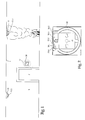
- Figure 1 are on the ceiling 1 of a building corridor in prescribed intervals automatic hazard detectors, here in the form of fire detectors 11 and 12 attached.
- automatic hazard detectors here in the form of fire detectors 11 and 12 attached.
- a door or a passage 2 to another hallway which are equipped with hazard detectors in the same way there is a manual hazard detector, here in Form of a push button detector 30, which on a corridor wall 3rd is mounted.
- Each automatic fire detector 11, 12 is not one represented control center connected and includes at least a bright LED 11.1, 12.1, which is usually the Has the function of an operating status display or with which the Detector is additionally equipped.
- the push button detector 30 includes the in generally accessible only after pressing in a pane Push button 31 or another, manually operable Mechanism of transmission after actuation an analog or digital signal to a control center (not shown) triggers.
- This push button has et al a window in which next to the printed symbol of a burning house three LEDs 30.1, 30.2, 30.3 for Signaling of the states "operation", “alarm” and "fault", which are usually assigned the colors green, red and yellow are arranged. Near the side edges This window has an additional LED on each side 30.4 and 30.5 arranged in the physical shape of an arrow. These LEDs 30.4 and 30.5 can be from the control center be switched from blinking to single.
- Figure 1 speaks the detector 11 for one or more sequelae of fire (Temperature, smoke, etc.) and gives a corresponding one Data telegram to the control center.
- a person presses the push button 30.1 of the push button detector 30, which then also sends an alarm signal to the Central sends.
- the computer in the central office solves that usual reactions intended for fire and Messages.
- the computer also determines the under Taking into account that caused by the alarm signal of the fire detector 11 localized danger location the usable escape routes and the exits to be driven on them, which are safe leading directions.
- the computer generates from this data Control commands that the LED 12.1 of the detector 12 and the corresponding LEDs of everyone on the escape route or routes following, not shown fire detector in a flashing mode relocate, specifically for the individual detectors delayed that for refugees the impression one signaling the direction of escape to be taken Running light is created.
- the computer Alternatively or simultaneously activated the computer in all on the escape route (s) lying push button detectors that LED in the form of a Arrow, which indicates the direction of escape, in the case of Push button detector 30, the LED 30.4 and also offset this into a flashing mode.
Landscapes
- Physics & Mathematics (AREA)
- General Physics & Mathematics (AREA)
- Business, Economics & Management (AREA)
- Emergency Management (AREA)
- Alarm Systems (AREA)
- Audible And Visible Signals (AREA)
- Fire Alarms (AREA)
Abstract
Description
- Fig. 1
- die Wand und die Decke eines Fluchtweges in einem Gebäude in schematischer Vereinfachung und
- Fig. 2
- die Einzelheit "X" in Fig. 1, d.h. einen manuellen Gefahrenmelder in vergrößerter Darstellung.
Claims (9)
- Verfahren zur Signalisierung der in einer Gefahrensituation einzuschlagenden Richtung eines Fluchtweges in einem Gebäude mit verteilt angeordneten Gefahrenmeldern, die an eine Gefahrenmeldezentrale angeschlossen sind, dadurch gekennzeichnet, dass die Gefahrenmelder mit Leuchtmitteln ausgestattet werden, die im Gefahrenfall von der Zentrale aus sequentiell nach Art eines Lauflichtes aktivierbar sind, das die von dem Gefahrenort wegführende Richtung des Fluchtweges bezeichnet.
- Verfahren nach Anspruch 1, dadurch gekennzeichnet, dass in der Zentrale eine Datei, die sämtliche Fluchtwege des Gebäudes und die physikalischen Orte sämtlicher Gefahrenmelder umfasst sowie ein Programm zur Ermittlung des oder der zu wählenden Fluchtwege in Abhängigkeit von einer oder mehreren einlaufenden Gefahrenmeldungen gespeichert wird, welches Programm die Daten des Anfangs, der Richtung und des Endes der von dem oder den ermittelten Gefahrenorten wegführenden Fluchtwege und daraus die Folge der Ansteuerbefehle der zu aktivierenden Leuchtmittel der Gefahrenmelder errechnet.
- Verfahren nach Anspruch 1 oder 2, dadurch gekennzeichnet, dass an die Zentrale zusätzlich die Leuchtmittel beleuchteter Fluchtwegkennzeichnungen angeschlossen werden und dass die Zentrale die auf dem/den ermittelten Fluchtweg(en) liegenden Fluchtwegkennzeichnungen in einen Blinkmodus versetzt.
- Verfahren nach Anspruch 3, dadurch gekennzeichnet, dass die Zentrale die Leuchtmittel derjenigen Fluchtwegkennzeichnungen, die im einem jeweiligen Gefahrenfall ungeeignete oder gefährliche Fluchtwege bezeichnen, abschaltet.
- Verfahren nach einem der Ansprüche 2 bis 4, dadurch gekennzeichnet, dass die physikalischen Orte der beleuchteten Fluchtwegkennzeichnungen in der Datei in der Zentrale abgelegt und in dem Fluchtwegermittlungsprogramm mitverarbeitet werden.
- Gefahrenmelder mit einer in dessen Ruhezustand grün leuchtenden LED, zur Durchführung des Verfahrens nach einem der Ansprüche 1 bis 5, dadurch gekennzeichnet, dass die LED im Gefahrenfall von der Zentrale aus in einen Blinkmodus schaltbar ist.
- Gefahrenmelder mit nach Anspruch 6, gekennzeichnet durch mindestens eine zusätzliche, leuchtstarke, grün leuchtende LED, die im Gefahrenfall von der Zentrale aus in einen Blinkmodus schaltbar ist.
- Gefahrenmelder nach Anspruch 7, dadurch gekennzeichnet, dass die zusätzliche LED körperlich als Pfeil ausgebildet ist.
- Manueller wandmontierbarer Gefahrenmelder zur Durchführung des Verfahrens nach einem der Ansprüche 1 bis 5, gekennzeichnet durch zwei als in entgegengesetzte Richtungen weisende Pfeile ausgestaltete LEDs, von denen entweder die eine oder die andere von der Zentrale aus situationsgerecht in einen Blinkmodus schaltbar ist.
Applications Claiming Priority (2)
| Application Number | Priority Date | Filing Date | Title |
|---|---|---|---|
| DE10246033 | 2002-10-02 | ||
| DE10246033A DE10246033B4 (de) | 2002-10-02 | 2002-10-02 | Fluchtleitsystem |
Publications (1)
| Publication Number | Publication Date |
|---|---|
| EP1408466A1 true EP1408466A1 (de) | 2004-04-14 |
Family
ID=32010108
Family Applications (1)
| Application Number | Title | Priority Date | Filing Date |
|---|---|---|---|
| EP03019001A Ceased EP1408466A1 (de) | 2002-10-02 | 2003-08-21 | Verfahren und Gefahrenmelder zur Signalisierung eines Fluchtweges |
Country Status (3)
| Country | Link |
|---|---|
| US (1) | US6998960B2 (de) |
| EP (1) | EP1408466A1 (de) |
| DE (1) | DE10246033B4 (de) |
Cited By (5)
| Publication number | Priority date | Publication date | Assignee | Title |
|---|---|---|---|---|
| DE102008042611A1 (de) | 2008-10-06 | 2010-04-08 | Robert Bosch Gmbh | Signaleinrichtung zur Signalisierung eines Fluchtweges sowie Fluchtwegsignalisierungssystem |
| EP2118865A4 (de) * | 2007-02-28 | 2011-11-02 | Honeywell Int Inc | In einen detektor oder ein modul integrierte notsignale |
| DE202012100157U1 (de) | 2012-01-17 | 2013-01-25 | P.E.R. Flucht- Und Rettungsleitsysteme Gmbh | Dynamisches Flucht- und Rettungsleitsystem |
| DE102012100348A1 (de) | 2012-01-17 | 2013-07-18 | P.E.R. Flucht- Und Rettungsleitsysteme Gmbh | Dynamisches flucht- und rettungsleitsystem |
| EP3082116A4 (de) * | 2013-12-11 | 2017-08-02 | TNK Corporation Ltd. | Führungssystem |
Families Citing this family (64)
| Publication number | Priority date | Publication date | Assignee | Title |
|---|---|---|---|---|
| US6773360B2 (en) * | 2002-11-08 | 2004-08-10 | Taylor Made Golf Company, Inc. | Golf club head having a removable weight |
| US7061392B2 (en) * | 2003-12-12 | 2006-06-13 | Honeywell International, Inc. | System and method of disabling an evacuation location device |
| US7619538B1 (en) * | 2005-05-12 | 2009-11-17 | Sanrose, LLC | Programmable, directing evacuation systems: apparatus and method |
| KR100690403B1 (ko) * | 2005-11-02 | 2007-03-09 | (주)인세이프테크 | 알에프 시스템을 이용한 전원 공급 점검 장치 |
| US7800511B1 (en) * | 2006-03-07 | 2010-09-21 | Living Space International, Inc. | Emergency lighting system |
| US7905645B2 (en) * | 2007-11-15 | 2011-03-15 | Batti Stephen A | Illuminated floor mat |
| US8118447B2 (en) | 2007-12-20 | 2012-02-21 | Altair Engineering, Inc. | LED lighting apparatus with swivel connection |
| DE102007061754A1 (de) * | 2007-12-20 | 2009-06-25 | Elektro Grundler Ges.M.B.H. & Co. Kg | Evakuierungsvorrichtung und Fluchtweganzeige hierfür |
| US7712918B2 (en) | 2007-12-21 | 2010-05-11 | Altair Engineering , Inc. | Light distribution using a light emitting diode assembly |
| US8120481B2 (en) * | 2008-02-12 | 2012-02-21 | Mark Gottlieb | Emergency services notification station and door unlock device |
| JP5281636B2 (ja) * | 2008-03-14 | 2013-09-04 | ホーチキ株式会社 | 防災端末装置 |
| US8360599B2 (en) | 2008-05-23 | 2013-01-29 | Ilumisys, Inc. | Electric shock resistant L.E.D. based light |
| FI122351B (fi) * | 2008-06-19 | 2011-12-15 | Marimils Oy | Menetelmä, järjestelmä ja laite ohjaamiseksi, opastamiseksi ja varoittamiseksi |
| US7976196B2 (en) | 2008-07-09 | 2011-07-12 | Altair Engineering, Inc. | Method of forming LED-based light and resulting LED-based light |
| US7946729B2 (en) | 2008-07-31 | 2011-05-24 | Altair Engineering, Inc. | Fluorescent tube replacement having longitudinally oriented LEDs |
| US8674626B2 (en) | 2008-09-02 | 2014-03-18 | Ilumisys, Inc. | LED lamp failure alerting system |
| US8256924B2 (en) | 2008-09-15 | 2012-09-04 | Ilumisys, Inc. | LED-based light having rapidly oscillating LEDs |
| US8653984B2 (en) | 2008-10-24 | 2014-02-18 | Ilumisys, Inc. | Integration of LED lighting control with emergency notification systems |
| US7938562B2 (en) | 2008-10-24 | 2011-05-10 | Altair Engineering, Inc. | Lighting including integral communication apparatus |
| US8901823B2 (en) | 2008-10-24 | 2014-12-02 | Ilumisys, Inc. | Light and light sensor |
| US8444292B2 (en) | 2008-10-24 | 2013-05-21 | Ilumisys, Inc. | End cap substitute for LED-based tube replacement light |
| US8214084B2 (en) | 2008-10-24 | 2012-07-03 | Ilumisys, Inc. | Integration of LED lighting with building controls |
| US8324817B2 (en) | 2008-10-24 | 2012-12-04 | Ilumisys, Inc. | Light and light sensor |
| GB0820606D0 (en) * | 2008-11-11 | 2008-12-17 | Patterson Kieran | Route guidance and evacuation system |
| NL2002295C2 (en) * | 2008-12-05 | 2009-12-14 | Michel Robert Ten Wolde | Illumination system including a variety of illumination devices. |
| US9679449B2 (en) | 2008-12-30 | 2017-06-13 | Oneevent Technologies, Inc. | Evacuation system |
| US8749392B2 (en) | 2008-12-30 | 2014-06-10 | Oneevent Technologies, Inc. | Evacuation system |
| US8556452B2 (en) | 2009-01-15 | 2013-10-15 | Ilumisys, Inc. | LED lens |
| US8362710B2 (en) | 2009-01-21 | 2013-01-29 | Ilumisys, Inc. | Direct AC-to-DC converter for passive component minimization and universal operation of LED arrays |
| US8664880B2 (en) | 2009-01-21 | 2014-03-04 | Ilumisys, Inc. | Ballast/line detection circuit for fluorescent replacement lamps |
| US9799205B2 (en) | 2013-07-15 | 2017-10-24 | Oneevent Technologies, Inc. | Owner controlled evacuation system with notification and route guidance provided by a user device |
| US8330381B2 (en) | 2009-05-14 | 2012-12-11 | Ilumisys, Inc. | Electronic circuit for DC conversion of fluorescent lighting ballast |
| US8299695B2 (en) | 2009-06-02 | 2012-10-30 | Ilumisys, Inc. | Screw-in LED bulb comprising a base having outwardly projecting nodes |
| CA2765200A1 (en) | 2009-06-23 | 2011-01-13 | Altair Engineering, Inc. | Illumination device including leds and a switching power control system |
| WO2011119958A1 (en) | 2010-03-26 | 2011-09-29 | Altair Engineering, Inc. | Inside-out led bulb |
| EP2553320A4 (de) * | 2010-03-26 | 2014-06-18 | Ilumisys Inc | Led-licht mit thermoelektrischem generator |
| CA2794512A1 (en) | 2010-03-26 | 2011-09-29 | Ilumisys, Inc. | Led light tube with dual sided light distribution |
| US8454193B2 (en) | 2010-07-08 | 2013-06-04 | Ilumisys, Inc. | Independent modules for LED fluorescent light tube replacement |
| EP2593714A2 (de) | 2010-07-12 | 2013-05-22 | iLumisys, Inc. | Leiterplattenhalterung für eine led-lichtröhre |
| WO2012058556A2 (en) | 2010-10-29 | 2012-05-03 | Altair Engineering, Inc. | Mechanisms for reducing risk of shock during installation of light tube |
| KR20120064543A (ko) * | 2010-12-09 | 2012-06-19 | 한국전자통신연구원 | 조명 지시 장치 및 방법 |
| US8870415B2 (en) | 2010-12-09 | 2014-10-28 | Ilumisys, Inc. | LED fluorescent tube replacement light with reduced shock hazard |
| US9072171B2 (en) | 2011-08-24 | 2015-06-30 | Ilumisys, Inc. | Circuit board mount for LED light |
| US9184518B2 (en) | 2012-03-02 | 2015-11-10 | Ilumisys, Inc. | Electrical connector header for an LED-based light |
| US9163794B2 (en) | 2012-07-06 | 2015-10-20 | Ilumisys, Inc. | Power supply assembly for LED-based light tube |
| US9271367B2 (en) | 2012-07-09 | 2016-02-23 | Ilumisys, Inc. | System and method for controlling operation of an LED-based light |
| US9285084B2 (en) | 2013-03-14 | 2016-03-15 | Ilumisys, Inc. | Diffusers for LED-based lights |
| US9267650B2 (en) | 2013-10-09 | 2016-02-23 | Ilumisys, Inc. | Lens for an LED-based light |
| JP2017504166A (ja) | 2014-01-22 | 2017-02-02 | イルミシス, インコーポレイテッドiLumisys, Inc. | アドレス指定されたledを有するledベース電灯 |
| US9979476B2 (en) * | 2014-03-25 | 2018-05-22 | Osram Sylvania Inc. | Techniques for indoor navigation with hazard avoidance via light-based communication |
| EP3123638B1 (de) | 2014-03-25 | 2018-07-18 | Osram Sylvania Inc. | Techniken zur innenraumnavigation mit belegungsverfolgung und standortverfolgung über lichtbasierte kommunikation |
| US10685402B1 (en) | 2014-04-25 | 2020-06-16 | State Farm Mutual Automobile Insurance Company | Systems and methods for homeowner-directed risk of property damage mitigation |
| US9510400B2 (en) | 2014-05-13 | 2016-11-29 | Ilumisys, Inc. | User input systems for an LED-based light |
| US10353359B1 (en) | 2014-10-07 | 2019-07-16 | State Farm Mutual Automobile Insurance Company | Systems and methods for managing smart devices based upon electrical usage data |
| DE202015100095U1 (de) | 2015-01-12 | 2015-02-06 | Kai Knierim | Vorrichtung zum Flucht- und Rettungswegmanagement |
| US10161568B2 (en) | 2015-06-01 | 2018-12-25 | Ilumisys, Inc. | LED-based light with canted outer walls |
| US11062574B2 (en) * | 2016-01-22 | 2021-07-13 | Tyco Fire & Security Gmbh | Strobe notification appliance and emergency lighting appliance with directional information |
| CA2929349C (en) * | 2016-04-29 | 2025-01-07 | Hubbell Incorporated | LIGHTING APPLIANCE |
| US10011460B2 (en) | 2016-09-27 | 2018-07-03 | Otis Elevator Company | Elevator dynamic displays for messaging and communication |
| CN110895723B (zh) * | 2018-09-13 | 2024-12-10 | 开利公司 | 火灾探测系统-用于火灾设备的火灾智能信号发送 |
| US11282350B2 (en) * | 2019-06-25 | 2022-03-22 | AVIDEA Group, Inc. | Firearm discharge detecting and semaphoring system and method |
| US11390392B2 (en) | 2019-11-18 | 2022-07-19 | Air Cruisers Company, LLC | Running/chasing lights for evacuation systems |
| AU2021200002A1 (en) * | 2020-01-05 | 2021-07-22 | Mitchell Lee Lewis | Safety corridor arrangement |
| US12431009B2 (en) * | 2023-08-02 | 2025-09-30 | Honeywell International Inc. | Integrated, interdependent system for verifying fire alarms |
Citations (2)
| Publication number | Priority date | Publication date | Assignee | Title |
|---|---|---|---|---|
| WO1996025729A1 (en) * | 1995-02-17 | 1996-08-22 | Rijlaarsdam Design Holding B.V. | Escape route indication system |
| WO2000014693A1 (de) * | 1998-09-09 | 2000-03-16 | Siemens Building Technologies Ag | Brandmelder und brandmeldeanlage |
Family Cites Families (15)
| Publication number | Priority date | Publication date | Assignee | Title |
|---|---|---|---|---|
| DE2441073C3 (de) * | 1974-08-27 | 1986-07-10 | Esser Sicherheitstechnik GmbH, 4040 Neuss | Anordnung zur Kenntlichmachung von Fluchtwegen durch Lichtquellen |
| US4385586A (en) * | 1981-09-04 | 1983-05-31 | Schriever Frederick G | Escape/rescue system |
| US4531114A (en) * | 1982-05-06 | 1985-07-23 | Safety Intelligence Systems | Intelligent fire safety system |
| US4737764A (en) * | 1986-05-30 | 1988-04-12 | Collins & Aikman Corporation | Modular floor covering units with built-in lighting |
| US4754266A (en) * | 1987-01-07 | 1988-06-28 | Shand Kevin J | Traffic director |
| GB2215105A (en) * | 1988-02-16 | 1989-09-13 | Richard William Henry Ford | Personnel evacuation system |
| GB2223871A (en) * | 1988-09-29 | 1990-04-18 | Colt Int Ltd | Escape route indication system |
| US5019805A (en) * | 1989-02-03 | 1991-05-28 | Flash-Alert Inc. | Smoke detector with strobed visual alarm and remote alarm coupling |
| DE4241862C2 (de) * | 1992-12-11 | 2001-03-01 | Ceag Sicherheitstechnik Gmbh | Sicherheitssystem sowie Verfahren, mit dem das Sicherheitssystem betrieben wird |
| JPH06231378A (ja) * | 1993-02-02 | 1994-08-19 | Souji Kobayashi | 避難口又は避難通路誘導装置 |
| US6025773A (en) * | 1998-02-09 | 2000-02-15 | Bresnan; William P. | Tactile safety guidance system for low visibility situations |
| US6150943A (en) * | 1999-07-14 | 2000-11-21 | American Xtal Technology, Inc. | Laser director for fire evacuation path |
| DE10001744A1 (de) * | 2000-01-17 | 2001-07-19 | Inprotec Innovative Produktion | Hinweis- und/oder Rettungszeichenleuchte |
| DE10048904A1 (de) * | 2000-10-02 | 2002-05-08 | Willing Gmbh Dr Ing | Rettungszeichenleuchten mit Leuchtdioden für abgesenkte Leuchtdichten im Batteriebetrieb |
| GB0027863D0 (en) * | 2000-11-15 | 2000-12-27 | Bligh Maurice | Emergency floor lighting system |
-
2002
- 2002-10-02 DE DE10246033A patent/DE10246033B4/de not_active Revoked
-
2003
- 2003-08-21 EP EP03019001A patent/EP1408466A1/de not_active Ceased
- 2003-09-29 US US10/671,631 patent/US6998960B2/en not_active Expired - Lifetime
Patent Citations (2)
| Publication number | Priority date | Publication date | Assignee | Title |
|---|---|---|---|---|
| WO1996025729A1 (en) * | 1995-02-17 | 1996-08-22 | Rijlaarsdam Design Holding B.V. | Escape route indication system |
| WO2000014693A1 (de) * | 1998-09-09 | 2000-03-16 | Siemens Building Technologies Ag | Brandmelder und brandmeldeanlage |
Cited By (6)
| Publication number | Priority date | Publication date | Assignee | Title |
|---|---|---|---|---|
| EP2118865A4 (de) * | 2007-02-28 | 2011-11-02 | Honeywell Int Inc | In einen detektor oder ein modul integrierte notsignale |
| DE102008042611A1 (de) | 2008-10-06 | 2010-04-08 | Robert Bosch Gmbh | Signaleinrichtung zur Signalisierung eines Fluchtweges sowie Fluchtwegsignalisierungssystem |
| DE202012100157U1 (de) | 2012-01-17 | 2013-01-25 | P.E.R. Flucht- Und Rettungsleitsysteme Gmbh | Dynamisches Flucht- und Rettungsleitsystem |
| DE102012100348A1 (de) | 2012-01-17 | 2013-07-18 | P.E.R. Flucht- Und Rettungsleitsysteme Gmbh | Dynamisches flucht- und rettungsleitsystem |
| DE102012100348B4 (de) | 2012-01-17 | 2018-08-16 | P.E.R. Flucht- Und Rettungsleitsysteme Gmbh | Dynamisches flucht- und rettungsleitsystem |
| EP3082116A4 (de) * | 2013-12-11 | 2017-08-02 | TNK Corporation Ltd. | Führungssystem |
Also Published As
| Publication number | Publication date |
|---|---|
| DE10246033A1 (de) | 2004-04-22 |
| US6998960B2 (en) | 2006-02-14 |
| US20040075572A1 (en) | 2004-04-22 |
| DE10246033B4 (de) | 2006-02-23 |
Similar Documents
| Publication | Publication Date | Title |
|---|---|---|
| DE10246033B4 (de) | Fluchtleitsystem | |
| EP1848509A2 (de) | Evakuierungssystem mit rettungskennzeichenleuchten | |
| DE19722406B4 (de) | Rettungszeichenleuchte und Sicherheitssystem | |
| DE19644126B4 (de) | Rettungsweg-Signalisierungssystem | |
| DE20002060U1 (de) | Leuchte | |
| EP1842991B1 (de) | Nottasterterminal mit kombinierter Anzeige | |
| DE202004002248U1 (de) | Handlauf mit Beleuchtung | |
| DE10001744A1 (de) | Hinweis- und/oder Rettungszeichenleuchte | |
| DE202004013455U1 (de) | Notfallhilfe | |
| DE10234300A1 (de) | Sicherungs- und Überwachungsvorrichtung für Türen, Fenster oder dergleichen | |
| WO2011123876A1 (de) | Verfahren zur beleuchtung eines raumes | |
| DE581318C (de) | Einrichtung zur Hand- und Fernsteuerung von Verkehrssignalen | |
| WO2008034527A1 (de) | Verfahren und anlage zur identifizierung eines gefahrenmelders | |
| DE4031364A1 (de) | Vorrichtung fuer die manuelle eingabe von fuer eine technische anlage bestimmten steuerdaten und fuer die anzeige von parametern der technischen anlage | |
| WO2009000681A1 (de) | Blitzleuchte für alarmmeldeanlagen | |
| DE504716C (de) | Beleuchtungseinrichtung fuer Leuchttuerme | |
| DE10002889A1 (de) | Lichtsteuerungssystem für eine Lauflichtanlage | |
| DE202004001695U1 (de) | Kombinierte feuersichere Verkleidungs- und Beleuchtungseinheit | |
| EP1437927A2 (de) | Leuchte | |
| CN206674260U (zh) | 颜色可变换的智能应急疏散标志灯 | |
| DE10349536A1 (de) | Nachleuchtendes Sicherheitskennzeichnungsmittel | |
| DE29616338U1 (de) | Selbstgespeiste Ausgangsleuchteinheit | |
| DE2524885A1 (de) | Notausgangsleuchte | |
| CN106535442A (zh) | 公共照明两地控制系统 | |
| EP3018271B1 (de) | Panikstange |
Legal Events
| Date | Code | Title | Description |
|---|---|---|---|
| PUAI | Public reference made under article 153(3) epc to a published international application that has entered the european phase |
Free format text: ORIGINAL CODE: 0009012 |
|
| AK | Designated contracting states |
Kind code of ref document: A1 Designated state(s): AT BE BG CH CY CZ DE DK EE ES FI FR GB GR HU IE IT LI LU MC NL PT RO SE SI SK TR |
|
| AX | Request for extension of the european patent |
Extension state: AL LT LV MK |
|
| 17P | Request for examination filed |
Effective date: 20040219 |
|
| 17Q | First examination report despatched |
Effective date: 20040819 |
|
| AKX | Designation fees paid |
Designated state(s): AT BE BG CH CY CZ DE DK EE ES FI FR GB GR HU IE IT LI LU MC NL PT RO SE SI SK TR |
|
| AXX | Extension fees paid |
Extension state: LV Payment date: 20040219 Extension state: LT Payment date: 20040219 |
|
| STAA | Information on the status of an ep patent application or granted ep patent |
Free format text: STATUS: THE APPLICATION HAS BEEN REFUSED |
|
| 18R | Application refused |
Effective date: 20051230 |