EP1409197B1 - Chuck for the support and alternative positioning of fixed and rotatable tools for drilling and/or milling, in tool machines - Google Patents
Chuck for the support and alternative positioning of fixed and rotatable tools for drilling and/or milling, in tool machines Download PDFInfo
- Publication number
- EP1409197B1 EP1409197B1 EP01963374A EP01963374A EP1409197B1 EP 1409197 B1 EP1409197 B1 EP 1409197B1 EP 01963374 A EP01963374 A EP 01963374A EP 01963374 A EP01963374 A EP 01963374A EP 1409197 B1 EP1409197 B1 EP 1409197B1
- Authority
- EP
- European Patent Office
- Prior art keywords
- rotatable part
- firmly connected
- rotatable
- chuck
- joining means
- Prior art date
- Legal status (The legal status is an assumption and is not a legal conclusion. Google has not performed a legal analysis and makes no representation as to the accuracy of the status listed.)
- Expired - Lifetime
Links
- 238000003801 milling Methods 0.000 title claims description 6
- 238000005553 drilling Methods 0.000 title claims description 5
- 239000011796 hollow space material Substances 0.000 claims abstract description 14
- 230000007246 mechanism Effects 0.000 claims description 13
- 238000006073 displacement reaction Methods 0.000 claims description 6
- 238000011084 recovery Methods 0.000 claims description 4
- 238000003754 machining Methods 0.000 description 2
- 230000015572 biosynthetic process Effects 0.000 description 1
- 230000002452 interceptive effect Effects 0.000 description 1
- 238000007789 sealing Methods 0.000 description 1
- 238000004804 winding Methods 0.000 description 1
Images



Classifications
-
- B—PERFORMING OPERATIONS; TRANSPORTING
- B23—MACHINE TOOLS; METAL-WORKING NOT OTHERWISE PROVIDED FOR
- B23B—TURNING; BORING
- B23B31/00—Chucks; Expansion mandrels; Adaptations thereof for remote control
- B23B31/02—Chucks
- B23B31/24—Chucks characterised by features relating primarily to remote control of the gripping means
- B23B31/26—Chucks characterised by features relating primarily to remote control of the gripping means using mechanical transmission through the working-spindle
- B23B31/261—Chucks characterised by features relating primarily to remote control of the gripping means using mechanical transmission through the working-spindle clamping the end of the toolholder shank
-
- B—PERFORMING OPERATIONS; TRANSPORTING
- B23—MACHINE TOOLS; METAL-WORKING NOT OTHERWISE PROVIDED FOR
- B23B—TURNING; BORING
- B23B3/00—General-purpose turning-machines or devices, e.g. centre lathes with feed rod and lead screw; Sets of turning-machines
- B23B3/16—Turret lathes for turning individually-chucked workpieces
- B23B3/161—Turret lathes for turning individually-chucked workpieces lathe with one toolslide carrying one turret head
- B23B3/162—Arrangements for performing other machining operations, e.g. milling, drilling
-
- B—PERFORMING OPERATIONS; TRANSPORTING
- B23—MACHINE TOOLS; METAL-WORKING NOT OTHERWISE PROVIDED FOR
- B23Q—DETAILS, COMPONENTS, OR ACCESSORIES FOR MACHINE TOOLS, e.g. ARRANGEMENTS FOR COPYING OR CONTROLLING; MACHINE TOOLS IN GENERAL CHARACTERISED BY THE CONSTRUCTION OF PARTICULAR DETAILS OR COMPONENTS; COMBINATIONS OR ASSOCIATIONS OF METAL-WORKING MACHINES, NOT DIRECTED TO A PARTICULAR RESULT
- B23Q16/00—Equipment for precise positioning of tool or work into particular locations not otherwise provided for
- B23Q16/02—Indexing equipment
- B23Q16/08—Indexing equipment having means for clamping the relatively movable parts together in the indexed position
- B23Q16/10—Rotary indexing
- B23Q16/102—Rotary indexing with a continuous drive
-
- B—PERFORMING OPERATIONS; TRANSPORTING
- B23—MACHINE TOOLS; METAL-WORKING NOT OTHERWISE PROVIDED FOR
- B23Q—DETAILS, COMPONENTS, OR ACCESSORIES FOR MACHINE TOOLS, e.g. ARRANGEMENTS FOR COPYING OR CONTROLLING; MACHINE TOOLS IN GENERAL CHARACTERISED BY THE CONSTRUCTION OF PARTICULAR DETAILS OR COMPONENTS; COMBINATIONS OR ASSOCIATIONS OF METAL-WORKING MACHINES, NOT DIRECTED TO A PARTICULAR RESULT
- B23Q5/00—Driving or feeding mechanisms; Control arrangements therefor
- B23Q5/02—Driving main working members
- B23Q5/04—Driving main working members rotary shafts, e.g. working-spindles
- B23Q5/10—Driving main working members rotary shafts, e.g. working-spindles driven essentially by electrical means
-
- B—PERFORMING OPERATIONS; TRANSPORTING
- B23—MACHINE TOOLS; METAL-WORKING NOT OTHERWISE PROVIDED FOR
- B23Q—DETAILS, COMPONENTS, OR ACCESSORIES FOR MACHINE TOOLS, e.g. ARRANGEMENTS FOR COPYING OR CONTROLLING; MACHINE TOOLS IN GENERAL CHARACTERISED BY THE CONSTRUCTION OF PARTICULAR DETAILS OR COMPONENTS; COMBINATIONS OR ASSOCIATIONS OF METAL-WORKING MACHINES, NOT DIRECTED TO A PARTICULAR RESULT
- B23Q5/00—Driving or feeding mechanisms; Control arrangements therefor
- B23Q5/22—Feeding members carrying tools or work
- B23Q5/28—Electric drives
-
- B—PERFORMING OPERATIONS; TRANSPORTING
- B23—MACHINE TOOLS; METAL-WORKING NOT OTHERWISE PROVIDED FOR
- B23B—TURNING; BORING
- B23B2260/00—Details of constructional elements
- B23B2260/084—Hirth couplings
Definitions
- the present invention relates to a chuck, in particular an electro chuck, in tool machines, comprising a stationary part, defining a hollow space extending longitudinally according to a rotational axis of the chuck and firmly connected to the tool machine and a rotatable part, for the support and alternative positioning of fixed tools and rotatable tools for drilling and/or milling, driven by an electric motor, positioned inside said hollow space and supported by this through a first and second group of rolling-contact bearings whose outer shell is connected firmly to said stationary part whereas the internal shell is firmly connected to said rotatable part, said groups of bearings being axially spaced apart along the rotational axis of the chuck, connecting means movable between a first position in which they connect to each other respective joining means firmly connected to said rotatable part and joining means firmly connected to said stationary part, making the rotatable part firmly connected to the stationary part, and a position in which such connecting means are axially disengaged from said joining means, thus allowing
- Chucks of the type indicated above are known in the technical field and are commonly employed to alternatively support fixed tools, suitable for carrying out turning operations, and rotatable tools, suitable for carrying out drilling or milling operations.
- the rotatable part of the chuck is locked and connected firmly to the stationary part; instead, when tools for drilling or milling operations are to be used, the rotatable part is let free to rotate and is driven by the electric motor that, in a conventional way, forms an integral part of the chuck itself.
- the connecting means that simultaneously engage with the joining means, in the form of Hirth teeth, carried both on the rotatable and fixed part, exert an axial thrust onto the rotatable part.
- Such thrust tends to be transferred onto the group of bearings arranged between the stationary part and rotatable part, respectively.
- the thrust is transferred onto the shell of the bearings which if force-fitted onto the rotatable part, thus forming a clearance of uncontrolled size on the bearing and without any possibility of recovering it when the rotatable part is detached from the stationary part and must therefore take on its specific task of driving rotating tools again.
- the purpose of the present invention is that of providing a chuck of the type indicated in the introduction, provided with a mechanisms for locking and unlocking the rotatable part with respect to the stationary part, which allows the imprecisions in the machining operations to be reduced, which derive from the uncontrolled formation of clearances between the parts submitted to the thrust of the connecting means.
- a chuck of the type which is directly driven by an electric motor incorporated onboard the chuck itself is indicated in its whole with 1.
- the stationary part of the chuck is indicated with 2; it is intended for being connected, for example, to a conventional, not illustrated slide, of a tool machine, in particular a lathe.
- the rotatable part of the chuck instead, is indicated with 3; it is connected to the stationary part 2 through a first group of bearings 4 and a second group of bearings 5, of the rolling-contact type, such as ball bearing.
- the respective outer shell 4a and 5a of the bearings is connected to the stationary part 2 of the chuck, respectively, whereas the respective inner shell 4b and 5b is force-fitted onto the rotatable part 3, respectively.
- This is equipped with a device, indicated in its whole with 6, for clamping and retaining a not illustrated tool, that, as it will be seen hereinbelow, can be a fixed tool for turning or a rotating tool, for example a drill tip or a milling cutter.
- the chuck comprises a mechanism for locking the rotatable part 3 to the stationary part 2, according to the operation to be carried out and thus according to the type of tool to be fit into the device 6 of the rotatable part.
- a mechanism is comprised of a first toothed crown, of the Hirth type, indicated with 7, firmly connected to the stationary part 2, arranged in correspondence of the front part 2a thereof, of a second toothed crown 8, also of the Hirth type, firmly connected to the rotatable part 3, and of a third toothed crown 9 carried by an annular member 10 housed within an annular hollow space formed between the stationary part 2 and the rotatable part 3.
- the toothed crowns 7 and 8 form the joining means respectively of the stationary and rotatable part, whereas the toothed crown 9 forms the connecting means suitable for engaging and disengaging the joining means.
- the toothed crown 8, firmly connected to the rotatable part 3, is connected thereto through a plurality of screws 8a and is arranged concentrically with respect to the toothed crown 7, firmly connected to the stationary part, axially aligned with a shoulder 2b of the stationary part 2.
- the annular member 10, with the toothed crown 9 is axially movable towards the toothed crowns 7 and 8 to engage these and hence lock the rotatable part 3 of the chuck to the stationary part 2, thus preventing it from rotating.
- the annular member 10 behaves therefore as a conventional hydraulic piston inside the hollow space 11 which form its cylinder through the interposition of conventional sealing means.
- the same shoulder 2b determines a fixed abutment plane against which the rotatable part 3 abuts when it is locked, with the full advantage of precision of working of the tool connected to said part.
- the groups of bearings 4 and 5 when the rotating part 3 is locked in the stationary part 2, are only stressed for the size of the clearance which is necessary to axially move the rotatable part 3 towards the shoulder 2b of the stationary part in that the further thrust exerted by the toothed crown 9 on the toothed crowns 7 and 8 is absorbed by the shoulder 2b.
- the chuck is equipped with a mechanism which, when the rotatable part 3 is unlocked from the stationary part 2, through the disengagement of the connection crown 9 from the crowns 7 and 8, allows the recuperation of the clearance build up in the groups of bearings 4 and 5 during the locked period and ensures that the rotatable part 3 is completely free to rotate and in particular not engaged with the shoulder 2b as illustrated in greater detail in figure 3.
- Such a mechanism comprises a ring 13 placed between the group of bearings 5 and the stationary part 2. With such a ring 13, more precisely, the outer shell 5a of the bearings engages. It can be axially displaced within a hollow space 14 formed between the rotatable part 3 and the stationary part 2 under the thrust of a plurality of elastic elements 15, for example coil springs, which react against the base 16 of respective houses 17 formed in the fixed part 2.
- Such elastic elements are preloaded so as to exert a thrust upon the ring 13 in the opposite direction to that according to which the annular element 10 carrying toothings 9 acts, when it determines the locking of the Hirth toothings 7 and 8.
- the mechanism for the recovery of the clearance also comprises a security device which operates when the rotatable part 3 is free to rotate with respect to the fixed part 2.
- the mechanism is made up of an annular member 18 housed inside an annular hollow space 19 also formed in the fixed part 2 of the chuck.
- the annular element 18 axially faces with its annular plane 18a, the ring 13 with respect to which it is separated with a predetermined axial clearance G.
- Such a clearance G is determined through the axial movement of the member 18 which, in the hollow space 19, functionally behaves like a cylinder which is defined by the washers 20 and 21, and by the pressure induced in the chamber 19a.
- the chuck according to the invention therefore allows operation with two different types of tool, fixed and rotating, with a high degree of precision of operation.
Landscapes
- Engineering & Computer Science (AREA)
- Mechanical Engineering (AREA)
- Gripping On Spindles (AREA)
- Jigs For Machine Tools (AREA)
- Finish Polishing, Edge Sharpening, And Grinding By Specific Grinding Devices (AREA)
Abstract
Description
- The present invention relates to a chuck, in particular an electro chuck, in tool machines, comprising a stationary part, defining a hollow space extending longitudinally according to a rotational axis of the chuck and firmly connected to the tool machine and a rotatable part, for the support and alternative positioning of fixed tools and rotatable tools for drilling and/or milling, driven by an electric motor, positioned inside said hollow space and supported by this through a first and second group of rolling-contact bearings whose outer shell is connected firmly to said stationary part whereas the internal shell is firmly connected to said rotatable part, said groups of bearings being axially spaced apart along the rotational axis of the chuck, connecting means movable between a first position in which they connect to each other respective joining means firmly connected to said rotatable part and joining means firmly connected to said stationary part, making the rotatable part firmly connected to the stationary part, and a position in which such connecting means are axially disengaged from said joining means, thus allowing the rotatable part to be put into rotation with respect to the stationary part through said electric motor.
- Chucks of the type indicated above are known in the technical field and are commonly employed to alternatively support fixed tools, suitable for carrying out turning operations, and rotatable tools, suitable for carrying out drilling or milling operations.
- If tools for turning operations are used, the rotatable part of the chuck is locked and connected firmly to the stationary part; instead, when tools for drilling or milling operations are to be used, the rotatable part is let free to rotate and is driven by the electric motor that, in a conventional way, forms an integral part of the chuck itself.
- An example of such a mechanism is shown in the document
EP-A-0 887 134 . - According to the known prior art indicated above, when the rotatable part of the chuck is locked to the stationary part, the connecting means that simultaneously engage with the joining means, in the form of Hirth teeth, carried both on the rotatable and fixed part, exert an axial thrust onto the rotatable part.
- Such thrust tends to be transferred onto the group of bearings arranged between the stationary part and rotatable part, respectively.
- In particular, the thrust is transferred onto the shell of the bearings which if force-fitted onto the rotatable part, thus forming a clearance of uncontrolled size on the bearing and without any possibility of recovering it when the rotatable part is detached from the stationary part and must therefore take on its specific task of driving rotating tools again.
- This is a serious drawback, since the machining operations are therefore affected by imprecisions which are not compatible with the conventional tolerances.
- The purpose of the present invention is that of providing a chuck of the type indicated in the introduction, provided with a mechanisms for locking and unlocking the rotatable part with respect to the stationary part, which allows the imprecisions in the machining operations to be reduced, which derive from the uncontrolled formation of clearances between the parts submitted to the thrust of the connecting means.
- The purpose is achieved by a chuck according to claim 1 with the attached drawings.
- The invention will be further described with reference to an example of an embodiment, provided only as an indication and without any limiting purposes, illustrated in the attached drawings, in which:
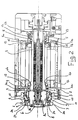
- figure 1 shows the chuck according to the invention in longitudinal section, in the position where the toothed joining means are disengaged and the rotatable part is free to rotate;
- figure 2 shows the mechanism of figure 1, in the position in which the toothed joining means are engaged with the connecting means and the rotatable part is locked and
- connected firmly to the stationary part;
- figure 3 is a detail of figure 1, in enlarged view;
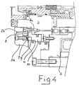
- figure 4 is a detail of figure 2 in enlarged view;
- figure 5 shows, in enlarged view, the mechanism for recovering the clearances in the position where the rotatable part is free to rotate about its axis;
- figure 6 shows in enlarged view, the mechanism of figure 5 in the position in which the rotatable part is locked to the fixed part.
- With reference to the aforementioned figures, a chuck of the type which is directly driven by an electric motor incorporated onboard the chuck itself, is indicated in its whole with 1.
- The stationary part of the chuck is indicated with 2; it is intended for being connected, for example, to a conventional, not illustrated slide, of a tool machine, in particular a lathe.
- The rotatable part of the chuck, instead, is indicated with 3; it is connected to the
stationary part 2 through a first group ofbearings 4 and a second group ofbearings 5, of the rolling-contact type, such as ball bearing. - The respective
outer shell stationary part 2 of the chuck, respectively, whereas the respectiveinner shell rotatable part 3, respectively. - This is equipped with a device, indicated in its whole with 6, for clamping and retaining a not illustrated tool, that, as it will be seen hereinbelow, can be a fixed tool for turning or a rotating tool, for example a drill tip or a milling cutter.
- The chuck comprises a mechanism for locking the
rotatable part 3 to thestationary part 2, according to the operation to be carried out and thus according to the type of tool to be fit into thedevice 6 of the rotatable part. Such a mechanism is comprised of a first toothed crown, of the Hirth type, indicated with 7, firmly connected to thestationary part 2, arranged in correspondence of thefront part 2a thereof, of a secondtoothed crown 8, also of the Hirth type, firmly connected to therotatable part 3, and of a thirdtoothed crown 9 carried by anannular member 10 housed within an annular hollow space formed between thestationary part 2 and therotatable part 3. - The
toothed crowns toothed crown 9 forms the connecting means suitable for engaging and disengaging the joining means. - The
toothed crown 8, firmly connected to therotatable part 3, is connected thereto through a plurality ofscrews 8a and is arranged concentrically with respect to thetoothed crown 7, firmly connected to the stationary part, axially aligned with ashoulder 2b of thestationary part 2. - The
annular member 10, with thetoothed crown 9 is axially movable towards thetoothed crowns rotatable part 3 of the chuck to thestationary part 2, thus preventing it from rotating. - With a reverse axial displacement, the
annular member 10 is moved away from thetoothed crowns rotatable part 3 which thus can be again driven in rotation by the conventional onboard electric motor, schematically represented by itselectric winding 12. - The
annular member 10 behaves therefore as a conventional hydraulic piston inside thehollow space 11 which form its cylinder through the interposition of conventional sealing means. - It should be noted that, as illustrated in detail in figure 4, when the
rotatable part 3 is locked to thestationary part 2, the thrust exerted by theannular element 10 on thetoothed crown 8 pushes against theshoulder 2b of thestationary part 2. - Moreover, the
same shoulder 2b determines a fixed abutment plane against which therotatable part 3 abuts when it is locked, with the full advantage of precision of working of the tool connected to said part. - In accordance with the invention, therefore, the groups of
bearings part 3 is locked in thestationary part 2, are only stressed for the size of the clearance which is necessary to axially move therotatable part 3 towards theshoulder 2b of the stationary part in that the further thrust exerted by thetoothed crown 9 on thetoothed crowns shoulder 2b. - Still in accordance with the invention, the chuck is equipped with a mechanism which, when the
rotatable part 3 is unlocked from thestationary part 2, through the disengagement of theconnection crown 9 from thecrowns bearings rotatable part 3 is completely free to rotate and in particular not engaged with theshoulder 2b as illustrated in greater detail in figure 3. - Such a mechanism comprises a
ring 13 placed between the group ofbearings 5 and thestationary part 2. With such aring 13, more precisely, theouter shell 5a of the bearings engages. It can be axially displaced within ahollow space 14 formed between therotatable part 3 and thestationary part 2 under the thrust of a plurality ofelastic elements 15, for example coil springs, which react against thebase 16 of respective houses 17 formed in thefixed part 2. - Such elastic elements are preloaded so as to exert a thrust upon the
ring 13 in the opposite direction to that according to which theannular element 10 carryingtoothings 9 acts, when it determines the locking of the Hirthtoothings - The mechanism for the recovery of the clearance also comprises a security device which operates when the
rotatable part 3 is free to rotate with respect to thefixed part 2. - The mechanism is made up of an
annular member 18 housed inside an annularhollow space 19 also formed in thefixed part 2 of the chuck. - As can be observed in greater detail in figure 5, the
annular element 18 axially faces with itsannular plane 18a, thering 13 with respect to which it is separated with a predetermined axial clearance G. - Such a clearance G is determined through the axial movement of the
member 18 which, in thehollow space 19, functionally behaves like a cylinder which is defined by thewashers - Should the
ring 13, during the operation with the rotating tool, receive an excessive axial thrust with the consequent risk of also undergoing a substantial axial displacement in the direction of lockage, the ring itself is contained by theannular plane 18a which acts as a shoulder for themember 13 after it has gone beyond the clearance G. - During the operation with fixed tools and thus with engaged
toothings annular member 18 being thrusted by thering 13. - From the above it is clear that, at the end of a working stage wherein, to allow the engagement of a fixed tool, the chuck was used with its rotatable part locked to the stationary part through the engagement of the
toothings toothing 9, one can go back to the position wherein the chuck operates with a rotatable tool, freeing thetoothings element 10. - Simultaneously to such an operation, the clearances which had formed as a consequence of the axial displacement of the
rotatable part 3 and which were derived from the thrust of theannular element 10 against thetoothing 8, are completely recovered by the action carried out by thesprings 15 against thering 13 which in turn transfers the recovery action of the axial clearance onto the groups ofbearings - Moreover, the distancing of the
toothed crown 8 from theshoulder 2b, and with this the freedom of rotation of therotatable part 3 of the chuck is assured without interfering with thestationary part 2. - The chuck according to the invention therefore allows operation with two different types of tool, fixed and rotating, with a high degree of precision of operation.
Claims (5)
- Chuck (1), in particular electro chuck in tool machines, comprising a stationary part (2), defining a hollow space (3a) extending longitudinally according to a rotational 1 axis (X-X) of the chuck (1) and firmly connected to the tool machine and a rotatable part, for the support and alternative positioning of fixed tools and rotatable tools for drilling and/or milling, driven by an electric motor, positioned inside said hollow space (3a) and supported by this through a first (4) and second (5) group of rolling-contact bearings whose outer shell (4a, 5a) is made firmly connected to said stationary part (2) whereas the internal shell (4b, 5b) is firmly connected to said rotatable part (3), said groups of bearings (4, 5) being axially spaced apart along the rotational axis (X-X) of the chuck, connecting means (9, 10) movable between a first position in which they connect to each other respective joining means (8) firmly connected to said rotatable part (3) and joining means (7) firmly connected to said stationary part (2), making the rotatable part (3) firmly connected to the stationary part (2), and a position in which such connecting means (9, 10) are axially disengaged from said joining means (7, 8), thus allowing the rotatable part (3) to be put into rotation with respect to the stationary part (2) through said electric motor (12), characterized by the fact that it comprises an annular shoulder (2b) arranged concentrically with respect to the rotatable part (3) in correspondence of the joining means (8) firmly connected thereto, said shoulder (2b) determining a bearing plane for said joining means (8) of the rotatable part (3) in the opposite direction to that of the locking exerted by said connecting means (9, 10), as well as a clearance recovery mechanism (13, 15) operative only when said rotatable part (3) is free to rotate around said stationary part (2), so to ensure the detachment of the rotatable part (3) from said shoulder (2b).
- Chuck according to claim 1, characterised in that said clearance recovery mechanism comprises a ring (13) arranged concentrically with respect to said rotatable part (3) within a first annular hollow space (14) of said stationary part (2), said ring (13) acting as support of the outer shell (5a) of the bearings (5) belonging to the group of bearings axially spaced apart from said connecting means (9, 10) and joining means (7, 8) and being free to move axially with respect to said hollow space (14), as well as an elastic member (15) arranged between said ring (13) and said stationary part (2), exerting a thrust onto the ring (13) in the opposite axial direction to that of the locking of said connecting means (9, 10) .
- Chuck according to claims 1 o 2, characterised in that said connecting means (9, 10) and said joining means (7) firmly connected to the stationary part (2) and said joining means (8) firmly connected to the rotatable part (3) are formed by annular members provided with front toothing of the Hirth type.
- Chuck according to claim 3, characterised in that said connecting means (9, 10) for connecting to each other the joining means (8) firmly connected to said rotatable part (3) and the joining means (7) firmly connected to said stationary part (2), respectively, are actuated by a respective annular hydraulic cylinder (10) arranged concentrically with respect to said rotatable part (3).
- Chuck according to any one of claims 2, 3 and 4, characterised in that it includes an annular member (18) housed within a second annular hollow space (19), acting as a hydraulic piston and cylinder in order to position the end (18a) of said member (18) at a predetermined axial distance (G) from said ring (13), said end (18a) forming an axial abutment of said ring (13), which limits its displacement in the direction of motion of said connecting means (9, 10) towards said joining means (7, 8).
Applications Claiming Priority (1)
| Application Number | Priority Date | Filing Date | Title |
|---|---|---|---|
| PCT/IT2001/000409 WO2003009963A1 (en) | 2001-07-26 | 2001-07-26 | Chuck for the support and alternative positioning of fixed and rotatable tools for drilling and/or milling, in tool machines |
Publications (3)
| Publication Number | Publication Date |
|---|---|
| EP1409197A1 EP1409197A1 (en) | 2004-04-21 |
| EP1409197B1 true EP1409197B1 (en) | 2008-01-30 |
| EP1409197B8 EP1409197B8 (en) | 2008-04-16 |
Family
ID=11133705
Family Applications (1)
| Application Number | Title | Priority Date | Filing Date |
|---|---|---|---|
| EP01963374A Expired - Lifetime EP1409197B8 (en) | 2001-07-26 | 2001-07-26 | Chuck for the support and alternative positioning of fixed and rotatable tools for drilling and/or milling, in tool machines |
Country Status (5)
| Country | Link |
|---|---|
| EP (1) | EP1409197B8 (en) |
| AT (1) | ATE385212T1 (en) |
| DE (1) | DE60132677T2 (en) |
| TW (1) | TWI226850B (en) |
| WO (1) | WO2003009963A1 (en) |
Cited By (2)
| Publication number | Priority date | Publication date | Assignee | Title |
|---|---|---|---|---|
| EP2269768A2 (en) | 2009-06-29 | 2011-01-05 | Maschinenfabrik Berthold Hermle AG | Tool spindle for a combined milling/turning machine with fixed or rotating tool |
| EP2881200A1 (en) | 2013-12-04 | 2015-06-10 | Gildemeister Drehmaschinen GmbH | Spindle unit for lathes and milling machines |
Families Citing this family (3)
| Publication number | Priority date | Publication date | Assignee | Title |
|---|---|---|---|---|
| EP2602056B1 (en) | 2011-12-07 | 2015-08-12 | Hurco Companies Inc. | tool-holding spindle with rotation locking means |
| DE102016116927A1 (en) * | 2016-09-09 | 2018-03-15 | Franz Kessler Gmbh | Release unit for a machine tool spindle |
| JP7454381B2 (en) * | 2020-01-09 | 2024-03-22 | オークマ株式会社 | Tool spindle position correction device for machine tools |
Family Cites Families (4)
| Publication number | Priority date | Publication date | Assignee | Title |
|---|---|---|---|---|
| US4570313A (en) * | 1984-12-31 | 1986-02-18 | G. A. Gray Division, The Warner & Swasey Company | Spindle lock-up device |
| EP0259517B1 (en) * | 1986-09-10 | 1989-08-16 | Schiess Aktiengesellschaft Geschäftsbereich Schiess-Froriep | Spindle for a machine tool quill provided with a socket for holding a turning or a milling tool |
| DE3928985A1 (en) * | 1989-09-01 | 1991-03-14 | Index Werke Kg Hahn & Tessky | WORKPIECE SPINDLE ARRANGEMENT FOR A LATHE |
| JP3167644B2 (en) * | 1997-06-20 | 2001-05-21 | 株式会社森精機製作所 | Tool spindle fixing device for compound machine tools |
-
2001
- 2001-07-26 DE DE60132677T patent/DE60132677T2/en not_active Expired - Lifetime
- 2001-07-26 EP EP01963374A patent/EP1409197B8/en not_active Expired - Lifetime
- 2001-07-26 WO PCT/IT2001/000409 patent/WO2003009963A1/en not_active Ceased
- 2001-07-26 AT AT01963374T patent/ATE385212T1/en not_active IP Right Cessation
-
2002
- 2002-04-30 TW TW091108919A patent/TWI226850B/en not_active IP Right Cessation
Cited By (3)
| Publication number | Priority date | Publication date | Assignee | Title |
|---|---|---|---|---|
| EP2269768A2 (en) | 2009-06-29 | 2011-01-05 | Maschinenfabrik Berthold Hermle AG | Tool spindle for a combined milling/turning machine with fixed or rotating tool |
| DE102009031027A1 (en) | 2009-06-29 | 2011-01-05 | Maschinenfabrik Berthold Hermle Ag | Tool spindle for a combined milling / lathe with stationary and rotating tool |
| EP2881200A1 (en) | 2013-12-04 | 2015-06-10 | Gildemeister Drehmaschinen GmbH | Spindle unit for lathes and milling machines |
Also Published As
| Publication number | Publication date |
|---|---|
| DE60132677T2 (en) | 2009-01-22 |
| WO2003009963A1 (en) | 2003-02-06 |
| ATE385212T1 (en) | 2008-02-15 |
| EP1409197A1 (en) | 2004-04-21 |
| DE60132677D1 (en) | 2008-03-20 |
| TWI226850B (en) | 2005-01-21 |
| EP1409197B8 (en) | 2008-04-16 |
Similar Documents
| Publication | Publication Date | Title |
|---|---|---|
| US5455993A (en) | Tool turret for a machine tool, in particular a lathe | |
| US6704983B2 (en) | Turret type tool post | |
| US4677719A (en) | Tool holding device for lathes | |
| US4596502A (en) | Device for positioning and locking turning, milling or other tool holders on to mobile lathe-machining center slides with an internal spindle | |
| US4275892A (en) | Force-balanced lathe chuck with safety ring | |
| US4789280A (en) | Tooling assembly for automatic tool changing | |
| US5007151A (en) | Machine tool turret | |
| US7287940B2 (en) | Device for fixing a tool on a shaft and machine spindle comprising same | |
| EP1383629B1 (en) | Positioning multifunctional mechanism for supporting tool-holding devices | |
| US4692074A (en) | Tool coupling arrangement for a tooling assembly | |
| US5027682A (en) | Attachment mounting mechanism in a machine tool | |
| US4704926A (en) | Turret for an automatic lathe | |
| EP1409197B8 (en) | Chuck for the support and alternative positioning of fixed and rotatable tools for drilling and/or milling, in tool machines | |
| US4026191A (en) | Machine tool | |
| US6640404B2 (en) | Three piece coupling arrangement for a turret indexing mechanism for a machine tool assembly and an air bearing assembly for the same | |
| US4856153A (en) | Spindle mechanism | |
| US6615466B1 (en) | Tool head with spindle bearing arrangement | |
| US4777714A (en) | Quick-change mount for chucks | |
| US4715102A (en) | Machine tool | |
| EP2620252B1 (en) | Turntable for supporting parts and/or tool holder units for machine tools | |
| US3311024A (en) | Rotary actuator power drawbolt for machine tool spindles | |
| EP2602056B1 (en) | tool-holding spindle with rotation locking means | |
| JP3597220B2 (en) | Workpiece mounting jig | |
| US5271134A (en) | Tool turret with axial reactive force | |
| JP7737412B2 (en) | Motor shaft |
Legal Events
| Date | Code | Title | Description |
|---|---|---|---|
| PUAI | Public reference made under article 153(3) epc to a published international application that has entered the european phase |
Free format text: ORIGINAL CODE: 0009012 |
|
| 17P | Request for examination filed |
Effective date: 20040116 |
|
| AK | Designated contracting states |
Kind code of ref document: A1 Designated state(s): AT BE CH CY DE DK ES FI FR GB GR IE IT LI LU MC NL PT SE TR |
|
| AX | Request for extension of the european patent |
Extension state: AL LT LV MK RO SI |
|
| GRAP | Despatch of communication of intention to grant a patent |
Free format text: ORIGINAL CODE: EPIDOSNIGR1 |
|
| GRAS | Grant fee paid |
Free format text: ORIGINAL CODE: EPIDOSNIGR3 |
|
| GRAA | (expected) grant |
Free format text: ORIGINAL CODE: 0009210 |
|
| AK | Designated contracting states |
Kind code of ref document: B1 Designated state(s): AT BE CH CY DE DK ES FI FR GB GR IE IT LI LU MC NL PT SE TR |
|
| REG | Reference to a national code |
Ref country code: GB Ref legal event code: FG4D |
|
| REG | Reference to a national code |
Ref country code: CH Ref legal event code: EP |
|
| REG | Reference to a national code |
Ref country code: IE Ref legal event code: FG4D |
|
| RAP2 | Party data changed (patent owner data changed or rights of a patent transferred) |
Owner name: DUPLOMATIC OLEODINAMICA S.P.A. |
|
| REF | Corresponds to: |
Ref document number: 60132677 Country of ref document: DE Date of ref document: 20080320 Kind code of ref document: P |
|
| RAP2 | Party data changed (patent owner data changed or rights of a patent transferred) |
Owner name: DUPLOMATIC AUTOMAZIONE S.P.A. |
|
| NLT2 | Nl: modifications (of names), taken from the european patent patent bulletin |
Owner name: DUPLOMATIC OLEODINAMICA S.P.A. Effective date: 20080312 |
|
| NLT2 | Nl: modifications (of names), taken from the european patent patent bulletin |
Owner name: DUPLOMATIC AUTOMAZIONE S.P.A. Effective date: 20080326 |
|
| PG25 | Lapsed in a contracting state [announced via postgrant information from national office to epo] |
Ref country code: ES Free format text: LAPSE BECAUSE OF FAILURE TO SUBMIT A TRANSLATION OF THE DESCRIPTION OR TO PAY THE FEE WITHIN THE PRESCRIBED TIME-LIMIT Effective date: 20080511 Ref country code: CH Free format text: LAPSE BECAUSE OF FAILURE TO SUBMIT A TRANSLATION OF THE DESCRIPTION OR TO PAY THE FEE WITHIN THE PRESCRIBED TIME-LIMIT Effective date: 20080130 Ref country code: LI Free format text: LAPSE BECAUSE OF FAILURE TO SUBMIT A TRANSLATION OF THE DESCRIPTION OR TO PAY THE FEE WITHIN THE PRESCRIBED TIME-LIMIT Effective date: 20080130 Ref country code: FI Free format text: LAPSE BECAUSE OF FAILURE TO SUBMIT A TRANSLATION OF THE DESCRIPTION OR TO PAY THE FEE WITHIN THE PRESCRIBED TIME-LIMIT Effective date: 20080130 |
|
| NLV1 | Nl: lapsed or annulled due to failure to fulfill the requirements of art. 29p and 29m of the patents act | ||
| REG | Reference to a national code |
Ref country code: CH Ref legal event code: PL |
|
| PG25 | Lapsed in a contracting state [announced via postgrant information from national office to epo] |
Ref country code: AT Free format text: LAPSE BECAUSE OF FAILURE TO SUBMIT A TRANSLATION OF THE DESCRIPTION OR TO PAY THE FEE WITHIN THE PRESCRIBED TIME-LIMIT Effective date: 20080130 |
|
| PG25 | Lapsed in a contracting state [announced via postgrant information from national office to epo] |
Ref country code: PT Free format text: LAPSE BECAUSE OF FAILURE TO SUBMIT A TRANSLATION OF THE DESCRIPTION OR TO PAY THE FEE WITHIN THE PRESCRIBED TIME-LIMIT Effective date: 20080630 Ref country code: BE Free format text: LAPSE BECAUSE OF FAILURE TO SUBMIT A TRANSLATION OF THE DESCRIPTION OR TO PAY THE FEE WITHIN THE PRESCRIBED TIME-LIMIT Effective date: 20080130 |
|
| PG25 | Lapsed in a contracting state [announced via postgrant information from national office to epo] |
Ref country code: NL Free format text: LAPSE BECAUSE OF FAILURE TO SUBMIT A TRANSLATION OF THE DESCRIPTION OR TO PAY THE FEE WITHIN THE PRESCRIBED TIME-LIMIT Effective date: 20080130 Ref country code: SE Free format text: LAPSE BECAUSE OF FAILURE TO SUBMIT A TRANSLATION OF THE DESCRIPTION OR TO PAY THE FEE WITHIN THE PRESCRIBED TIME-LIMIT Effective date: 20080430 Ref country code: DK Free format text: LAPSE BECAUSE OF FAILURE TO SUBMIT A TRANSLATION OF THE DESCRIPTION OR TO PAY THE FEE WITHIN THE PRESCRIBED TIME-LIMIT Effective date: 20080130 |
|
| EN | Fr: translation not filed | ||
| PLBE | No opposition filed within time limit |
Free format text: ORIGINAL CODE: 0009261 |
|
| STAA | Information on the status of an ep patent application or granted ep patent |
Free format text: STATUS: NO OPPOSITION FILED WITHIN TIME LIMIT |
|
| 26N | No opposition filed |
Effective date: 20081031 |
|
| GBPC | Gb: european patent ceased through non-payment of renewal fee |
Effective date: 20080726 |
|
| PG25 | Lapsed in a contracting state [announced via postgrant information from national office to epo] |
Ref country code: MC Free format text: LAPSE BECAUSE OF NON-PAYMENT OF DUE FEES Effective date: 20080731 |
|
| PG25 | Lapsed in a contracting state [announced via postgrant information from national office to epo] |
Ref country code: FR Free format text: LAPSE BECAUSE OF FAILURE TO SUBMIT A TRANSLATION OF THE DESCRIPTION OR TO PAY THE FEE WITHIN THE PRESCRIBED TIME-LIMIT Effective date: 20081121 |
|
| PG25 | Lapsed in a contracting state [announced via postgrant information from national office to epo] |
Ref country code: GB Free format text: LAPSE BECAUSE OF NON-PAYMENT OF DUE FEES Effective date: 20080726 |
|
| PG25 | Lapsed in a contracting state [announced via postgrant information from national office to epo] |
Ref country code: IE Free format text: LAPSE BECAUSE OF NON-PAYMENT OF DUE FEES Effective date: 20080728 Ref country code: CY Free format text: LAPSE BECAUSE OF FAILURE TO SUBMIT A TRANSLATION OF THE DESCRIPTION OR TO PAY THE FEE WITHIN THE PRESCRIBED TIME-LIMIT Effective date: 20080130 |
|
| PG25 | Lapsed in a contracting state [announced via postgrant information from national office to epo] |
Ref country code: LU Free format text: LAPSE BECAUSE OF NON-PAYMENT OF DUE FEES Effective date: 20080726 |
|
| PG25 | Lapsed in a contracting state [announced via postgrant information from national office to epo] |
Ref country code: TR Free format text: LAPSE BECAUSE OF FAILURE TO SUBMIT A TRANSLATION OF THE DESCRIPTION OR TO PAY THE FEE WITHIN THE PRESCRIBED TIME-LIMIT Effective date: 20080130 |
|
| PG25 | Lapsed in a contracting state [announced via postgrant information from national office to epo] |
Ref country code: GR Free format text: LAPSE BECAUSE OF FAILURE TO SUBMIT A TRANSLATION OF THE DESCRIPTION OR TO PAY THE FEE WITHIN THE PRESCRIBED TIME-LIMIT Effective date: 20080501 |
|
| PGFP | Annual fee paid to national office [announced via postgrant information from national office to epo] |
Ref country code: DE Payment date: 20190719 Year of fee payment: 19 Ref country code: IT Payment date: 20190731 Year of fee payment: 19 |
|
| REG | Reference to a national code |
Ref country code: DE Ref legal event code: R119 Ref document number: 60132677 Country of ref document: DE |
|
| PG25 | Lapsed in a contracting state [announced via postgrant information from national office to epo] |
Ref country code: DE Free format text: LAPSE BECAUSE OF NON-PAYMENT OF DUE FEES Effective date: 20210202 |
|
| PG25 | Lapsed in a contracting state [announced via postgrant information from national office to epo] |
Ref country code: IT Free format text: LAPSE BECAUSE OF NON-PAYMENT OF DUE FEES Effective date: 20200726 |