EP1410969A2 - Umschalt-Einrichtung für Anhängerbremsventil - Google Patents
Umschalt-Einrichtung für Anhängerbremsventil Download PDFInfo
- Publication number
- EP1410969A2 EP1410969A2 EP03017153A EP03017153A EP1410969A2 EP 1410969 A2 EP1410969 A2 EP 1410969A2 EP 03017153 A EP03017153 A EP 03017153A EP 03017153 A EP03017153 A EP 03017153A EP 1410969 A2 EP1410969 A2 EP 1410969A2
- Authority
- EP
- European Patent Office
- Prior art keywords
- valve
- switching
- port
- trailer brake
- pneumatic
- Prior art date
- Legal status (The legal status is an assumption and is not a legal conclusion. Google has not performed a legal analysis and makes no representation as to the accuracy of the status listed.)
- Granted
Links
Images


Classifications
-
- F—MECHANICAL ENGINEERING; LIGHTING; HEATING; WEAPONS; BLASTING
- F15—FLUID-PRESSURE ACTUATORS; HYDRAULICS OR PNEUMATICS IN GENERAL
- F15C—FLUID-CIRCUIT ELEMENTS PREDOMINANTLY USED FOR COMPUTING OR CONTROL PURPOSES
- F15C3/00—Circuit elements having moving parts
- F15C3/005—Circuit elements having moving parts using loose plates or foils
-
- B—PERFORMING OPERATIONS; TRANSPORTING
- B60—VEHICLES IN GENERAL
- B60T—VEHICLE BRAKE CONTROL SYSTEMS OR PARTS THEREOF; BRAKE CONTROL SYSTEMS OR PARTS THEREOF, IN GENERAL; ARRANGEMENT OF BRAKING ELEMENTS ON VEHICLES IN GENERAL; PORTABLE DEVICES FOR PREVENTING UNWANTED MOVEMENT OF VEHICLES; VEHICLE MODIFICATIONS TO FACILITATE COOLING OF BRAKES
- B60T11/00—Transmitting braking action from initiating means to ultimate brake actuator without power assistance or drive or where such assistance or drive is irrelevant
- B60T11/10—Transmitting braking action from initiating means to ultimate brake actuator without power assistance or drive or where such assistance or drive is irrelevant transmitting by fluid means, e.g. hydraulic
- B60T11/28—Valves specially adapted therefor
- B60T11/32—Automatic cut-off valves for defective pipes
- B60T11/326—Automatic cut-off valves for defective pipes in pneumatic systems
Definitions
- the invention relates to a switching device for a trailer brake valve provided in a trailer.
- A1 is a trailer brake valve for a Trailer with electronic brake control (trailer EBS control) known; on the D1 here is full content Referenced. Due to use in trailers with EBS regulation there is no need for a Air quantity gain through a relay valve, and so on is the trailer brake valve after the D1 as a slide valve built up.
- This trailer brake valve [there (8)] has two positions on, a valve basic position [there Fig. 2a, Fig. 3], in which the supply pressure hose of the towing vehicle [there (30)] to the red coupling head of the trailer [there (48)] is connected, and one Valve tear-off position [there Fig. 2b, Fig. 4], in the no connection of supply pressure hose to red Coupling head exists.
- Fig. 4 is as Switching device for changing between the valve basic position and the valve breakaway a pilot valve [there (60)] provided there in Fig. 5a, Fig. 5b is structurally explained.
- This pilot valve consists of a spring-loaded conical valve switching element [there (62), Fig. 5b], which in the case that at the supply terminal [There (1)] is no pressure -d. H. in the demolition on a first valve seat [there (63)] is applied. If the pressure at the supply connection increases, then forms according to the effective diameter [there (65)] of the first valve seat on a compressive force the valve switching element off. The rising pressure reached the shift pressure threshold when the pressure force the same by the return spring [there (61)] on the Valve switch is applied counterforce, and at Exceeding the switching pressure threshold raises the valve switching element from the first valve seat. The built up Air pressure then acts on the now larger area of the Valve switching element, so that the valve switching member at the second valve seat [there (64)] comes to rest, which has a larger effective diameter [there (66), Fig. 5a].
- the compressor in the towing vehicle is responsible for the capacity and thus for the pressure gradient in the pressure increase; here it is assumed that the delivery rate in the "worst case" case is 100 Ndm 3 / min [standard liters per minute].
- the minimum delivery rate at the supply input of the trailer brake valve 50 is Ndm 3 / min; this value represents the minimum trailer supply.
- D2 From DE 101 39 757 A1 [hereinafter referred to as D2] is a trailer brake valve known, too for a trailer with electronic brake control is provided.
- D2 to which also here completely contents reference is a separate parking terminal for the Connection of a parking valve as part of a conventional double-release valve intended.
- the D2 will as additional security with the trailer off, d. H. when the trailer brake valve in its tear position located in the driving position of the parking valve via the trailer brake valve parking connection Bypassing the usual check valve, reservoir pressure fed into the spring-loaded dissolving chambers, as usual in the tear position, the spring-loaded service brake chambers over the brake pressure connection are acted upon with reservoir pressure.
- the D2 is an explained switching device of the D1 equal constructed switching device as a pilot valve to switch between the basic and Abrißwolfen the trailer brake valve provided.
- the invention is therefore based on the object, a switching device in particular for a trailer brake valve to change between the valve home position and to indicate the valve breakaway position, which is a safe Valve switching even at a fixed, comparatively low trailer capacity guaranteed.
- the invention has the advantage that the switching device not just for changing positions Trailer brake valve, but also as an independent Valve device can be used for completely different applications is.
- the property is the Switching device as position-stable shuttle valve
- a stable switching pressure threshold with only a very small required switching airflow guaranteed.
- a housing (29) arranged pneumatic switching valve device (12) from a loaded with a switching valve spring (35) Valve switching element, as the rotationally symmetrical H-shaped valve switch body (17) formed is and along a housing-fixed circular cylindrical Guide surface (22) slidably and in a valve switch actuation direction, namely against the direction of action the shift valve spring (35), displaceable is stored, wherein the direction of the circular cylinder axis against the action of the switching valve spring (35) the Valve switch actuating direction represents.
- the switching valve device (12) For the switching valve device (12) are a pneumatic input (13), a pneumatic switching outlet (32) and a pneumatic vent outlet (14) provided; there are still a first (15) and second [(16), FIG. 2] valve seat provided, wherein at unpressurized inlet (13) of the valve switching body (17) by the force of the switching valve spring (35) on the first Valve seat (15) is applied; this is the starting position the valve device (12).
- the H-shaped valve switching body (17) is shown in Fig. 3a shown; it consists of a centrally arranged Closing body (41) in the form of a circular disk with a first (18) and a second (19) elastomeric sealing element and one with the closing body (41) preferably integrally connected guide body (42) in Shape of a rotationally symmetrical hollow body.
- Fig. 3a are dashed imaginary Dividing lines (43) between the closing body (41) and the guide body (42) drawn.
- the Guide body (42) is formed with a barrel-shaped, convex curved outer surface.
- a support surface (39) is provided, the center between the respective valve seats (15, 16) facing outer surfaces of the elastomer sealing elements (18) and (19) is arranged so that the lateral force component the switching valve spring (35) in the median plane of the Valve switching element (17) engages and thus the influence the lateral force on both elastomer sealing elements (18, 19) takes place on average with the lowest tilting effect, relative to the central axis of the valve switching body (17).
- This will be for the below explained, especially critical switching to the valve switching position 2, that the valve body (17) lifts parallel from the first valve seat (15).
- Fig. 1 is on the circular cylindrical guide surface (22) a circumferential one at least one place annular formation (23) provided on the housing (29), which narrows the diameter.
- dashed line a section (1b) drawn, which is shown enlarged in Fig. 1b.
- a Narrow throttle ring gap (24) with fixed width educated.
- FIG. 1a of the dashed lines Section (1a) of FIG. 1 shows the embodiment the first valve seat (15).
- the structure This valve seat also corresponds to the structure of the second valve seat (16) according to Fig. 2a after the Section (2a) in the explained below Fig. 2, the This will also be explained.
- Both valve seats (15, 16) have the basic shape of a Circular ring, which through an outer circle with larger Diameter and an inner circle with smaller Diameter is determined.
- the area between the outer and the inner circle designed as a conical section surface, whereby a circular sealing edge is formed when the support on the corresponding elastomeric sealing element this slightly deformed and the sealing seat closes [the sealing edge as a circular "cutting edge" on the inner circle acts according to Fig. 1a on the first elastomeric sealing element (18) on; in the case of Fig. 2a of the acts second valve seat (16) on the outer circle on the second Elastomer sealing element (19) a].
- the angle of the conical surface of the valve seats (15, 16) opposite the axis is z. B. 85 °; for the protection of Elastomer sealing elements are the "cutting edges" of the sealing edges slightly rounded, z. B. with a radius of 0.5 mm.
- the effective diameter of a valve seat is through the diameter of the area determined over the air with their pressure on the valve body (17) act can; this is considering the elastomer indentation free area on the respective elastomer sealing element in the state of each closed Sealing seat.
- the elastomer indentation comparatively is low, is the effective diameter a valve seat practically only by the diameter the circular sealing edge determined.
- first valve seat (15) is the above-mentioned "free area" by the diameter (36) determined, which neglecting the elastomer indentation equal to the diameter of the circular Sealing edge is, and this is in turn by the inner Circle of the circular ring basic shape of the first valve seat (15).
- FIG. 1c Corresponding to the section line (1c) shown in FIG. is a section through the switching valve device in Fig. 1c (12).
- the illustration shows three air channels (30), which in the circumferential direction around each 120 degrees offset against each other. It is at least an air duct (30) is provided, wherein more be used as the illustrated three air ducts can.
- the cross section and the number of air channels (30) is determined by the required airflow in the valve switching state of FIG. 2, see below.
- the above-described throttle ring gap (24) is now dimensioned so that at that specified for the switching valve device (12) minimum flow rate at the pneumatic inlet (13) the throttle effect of the throttle ring gap (24) is sufficiently large for the over the "tilted" first sealing seat (15, 17) in the pressure chamber (40) inflowing air quantity not fast over the Air ducts (30) to the pneumatic vent outlet (14) is derived, but that also in this low flow rate a back pressure in the pressure chamber (40) can build up. If this back pressure then so big has become that the biasing force of the switching valve spring (35) is safely exceeded, then raises the Valve switch body (17) completely from the first valve seat (15) from and is the second force on the pressure Valve seat (16) pushed according to FIG. 2, the to be closed.
- valve switching member displaceable in a normal longitudinal guide arranged so that the switching element at each position remains in the same orientation.
- the axis of the guide tube is the axis of movement and coincides the axis of the valve switching element together. This is the valve switching element forced, and the only one Degree of freedom is the axis of motion.
- valve switching member (17) a further degree of freedom, because this around the center of rotation of the crown is pivotally and thereby the second elastomeric sealing element (19) virtually powerless on the second Valve seat (16) can align and the required Force to fully shoot the sealing line with it is comparatively much reduced.
- the effective sealing surface of the first valve seat (15), determined by the diameter (36), smaller than the effective sealing area of the second valve seat (16), by the diameter (37) is determined according to Fig. 2a.
- the guide body extends (42), starting from the circular disk-shaped Closing body (41) with the first (18) and the second (19) Elastomer sealing element, which in this case in corresponding recesses of the closing body (41) z. B. are vulcanized, spatially in the direction of the first Valve seat [cf. Fig. 4], whereby a valve switching body is formed with ⁇ -shaped cross-section.
- the support surface is (39) for the switching valve spring (35) [see. Fig.
- FIG. 4 shows the ⁇ -shaped valve switching body (38) According to Fig. 3b, inserted into the housing (29) for a Switching valve device (12) according to FIG. 1 in the valve starting position.
- valve switching body (17) in Fig. 2 For the representation of the switching valve device (12) with the ⁇ -shaped valve switching body (38) in the valve switching position Reference is made to FIG. 2; in the same Way, as shown in FIG. 4 by replacing the valve switching body (17) through the valve switching body (38) is formed, the valve switching body (17) in Fig. 2 by the valve switching body (38) of FIG. 3b be replaced; the valve switching operations are identical to the operations described under Fig. 2.
- FIG. 5 and Fig. 7 shows a switching valve device with a ⁇ -shaped valve switching element (38) in the valve switching position shown; in these illustrations, the switching valve device as a pilot valve in a trailer brake valve integrated.
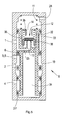
- the switching valve means (12) is after Fig. 4 in the valve spool (10) of a described in D1 Trailer brake valve (8) [D1: Trailer brake valve there Fig. 4, (8)] integrated such that this replaces the pilot valve [there (60)], wherein the supply connection (1) of the Trailer brake valve (8) via the pneumatic channel (25) in the valve spool (10) with the input (13) of the switching valve device (12) is connected; the unpressurized Input (13) of the switching valve device (12) corresponds to the unpressurized valve breakaway position of the Trailer brake valve.
- Fig. 5 is in the valve-home position the switching valve device (12) the piston chamber (34) for the valve spool (10) via one in the valve spool (10) arranged pressure channel (33), the switching output (32) and the pneumatic vent outlet (14) the switching valve device (12), and finally the trailer brake valve vent (28) vented, and so by the action of the return spring (11) in 5 present valve breakaway position of Trailer brake valve (8) of the valve slide (10) to the second stop (27) applied [a first stop (26) will be explained in connection with Fig. 6].
- FIG. 6 indicates a pressure at the supply connection (1)
- FIG. the pressure threshold of the valve switching device (12) exceeds; in the above explained Way lifts the valve body (17) from the first valve seat (15) and lies against the second valve seat (16).
- the voltage applied to the supply connection (1) becomes now via the pneumatic input (13) and the switching output (32) of the switching valve means (12) in the Pressure channel (33) and in the piston chamber (34) transferred, and according to the effective piston area of the valve spool (10), a compressive force is formed on the valve spool (10) showing the force of the prestressed Return spring (11) overcomes and the valve spool (10) pushes against the first stop (26) where he comes to the plant.
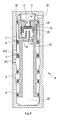
- the D2 is therefore in the housing of the trailer brake valve (9) as a further connection a parking connection (21) provided in the valve starting position of the Switching valve device (12) and thus in the tear-off position of the trailer brake valve (9) of FIG. 7 via the pneumatic channel (31) directly to the container port (3) is connected.
- Fig. 8 is located at the supply input (1) of the trailer brake valve (9) the pressure threshold of the switching valve device (12) exceeding pressure, so that in the manner explained above, the valve switching body (17) abuts the second valve seat (16), and accordingly the also explained effect of the switching valve device (12) as pilot valve of Valve slide (20) against the biasing force of the return spring (11) to the first stop (26) driven is, whereby the trailer brake valve (9) its basic position occupies.
- connection of the parking connection (21) of FIG. 7 is the above-mentioned additional security at one parked without sunken spring brakes Trailer [non-actuated spring-loaded release valve] guaranteed by at each pressure level of Pressure Reservoir Tank in Trailer A Residual Braking Effect is present for the trailer, either from comes from the service or parking brakes.
- valve switching body (17) according to Fig. 3a with the complementary shown in Fig. 1 Means for a defined switching to others Valve constructions is applicable, are shown in Fig. 9 and Fig. 10 Applications of this valve technology on a shuttle valve (45) and a check valve (46) shown; Moreover, in these representations, the H-shaped Valve switching member (17) also by a ⁇ -shaped Valve switch (38) are replaced.
- shuttle valve (45) of FIG. 9 also known as Double check valve is called and its pneumatic Circuit symbol is shown in Fig. 9a, the larger one will be at the two input terminals (13) and (14) applied pressure at the output (32) output; this corresponds to the "select-high" function.
- valve seats (15, 16) have a identical effective diameter on [the Do not express directly, but compared "weighted” it is also possible, both valve seats equip with different effective diameters].
- the construction is characterized by an exact defined switching point and a very low switching airflow out.
- valve switching body (17) adjoins the valve seat (15) to the completed one Switching state [Applying the valve body (17) to the Support body (44)] apply here as well the advantages explained an exact switching pressure and a minimum Valve switching air flow.
Landscapes
- Engineering & Computer Science (AREA)
- Mechanical Engineering (AREA)
- Transportation (AREA)
- General Engineering & Computer Science (AREA)
- Theoretical Computer Science (AREA)
- Physics & Mathematics (AREA)
- Fluid Mechanics (AREA)
- Multiple-Way Valves (AREA)
- Valves And Accessory Devices For Braking Systems (AREA)
- Braking Systems And Boosters (AREA)
Abstract
Description
- Fig. 1
- Die Umschalt-Ventileinrichtung in ihrer Ventil-Ausgangsstellung bei drucklosem Pneumatikeingang;
- Fig. 2
- die Umschalt-Ventileinrichtung in ihrer Ventil-Schaltstellung bei Druckbeaufschlagung des Pneumatikeingangs;
- Fig. 3a
- den Ventilschaltkörper für die Umschalt-Ventileinrichtung in H-Form
- Fig. 3b
- den Ventilschaltkörper für die Umschalt-Ventileinrichtung in Π-Form;
- Fig. 4
- die Umschalt-Ventileinrichtung nach Fig. 1 bei Verwendung eines Ventilschaltkörpers nach Fig. 3b;
- Fig. 5
- ein Anhängerbremsventil, das von einem Anhängerbremsventil nach der D1 ausgeht, in dessen Ventilschieber die Umschalt-Ventileinrichtung integriert ist, und zwar in ihrer Ventil-Ausgangsstellung entsprechend Fig. 4, bei der sich das Anhängerbremsventil in seiner Ventil-Abrißstellung befindet;
- Fig. 6
- das Anhängerbremsventil nach Fig. 5, bei dem sich die Umschalt-Ventileinrichtung entsprechend Fig. 2 in der Ventil-Schaltstellung befindet, und bei der das Anhängerbremsventil in seine Ventil-Grundstellung versetzt ist;
- Fig. 7
- ein Anhängerbremsventil, das von einen Anhängerbremsventil nach der D2 ausgeht, in dessen Ventilschieber die Umschalt-Ventileinrichtung integriert ist, und zwar in ihrer Ventil-Ausgangsstellung entsprechend Fig. 4, bei der sich das Anhängerbremsventil in seiner Ventil-Abrißstellung befindet;
- Fig. 8
- das Anhängerbremsventil nach Fig. 7, bei dem sich die Umschalt-Ventileinrichtung entsprechend Fig. 2 in der Ventil-Schaltstellung befindet, und bei der das Anhängerbremsventil in seine Ventil-Grundstellung versetzt ist;
- Fig. 9
- die Konstruktion eines Wechselventils unter Nutzung der Technik des erfindungsgemäßen Ventilschaltkörpers nach Fig. 3a;
- Fig. 10
- die Konstruktion eines Rückschlagventils unter Nutzung der Technik des erfindungsgemäßen Ventilschaltkörpers nach Fig. 3a.
- ein Versorgungsanschluß (1), der im Anhänger mit dem roten Kupplungskopf für den Vorrats-Druckschlauch verbunden ist;
- ein Bremsvorgabeanschluß (4), der im Anhänger mit dem gelben Kupplungskopf für den Brems-Druckschlauch verbunden ist;
- ein Behälteranschluß (3), der im Anhänger mit dem Druckluft-Vorratsbehälter verbunden ist;
- ein Bremsdruckanschluß (2) zur Ausgabe des Bremsdruckes an die Bremseinrichtung des Anhängers;
- ein Löseanschluß (5) zum Anschluß eines Löseventils für das Lösen der Feststellbremsen eines abgestellten Anhängers;
- eine Anhängerbremsventil-Entlüftung (28) zur Atmosphäre.
- Der am Versorgungsanschluß (1) anliegende Druckraum ist zwar über den geschlossenen ersten Ventilsitz (15) der Umschalt-Ventileinrichtung (12)pneumatisch abgeschlosssen, jedoch ist über das Rückschlagventil (6) eine pneumatische Verbindung zum Behälteranschluß (3) hergestellt;
- der Bremsdruckanschluß (2) ist mit dem Behälteranschluß (3) verbunden.
- Der Versorgungsanschluß (1) ist über das Rückschlagventil (6) mit dem Behälteranschluß (3) verbunden;
- der Bremsdruckanschluß (2) ist mit dem Bremsvorgabeanschluß (4) verbunden.
- In der Ventil-Ausgangsstellung der Umschalt-Ventileinrichtung (12) nach Fig. 7 ist der Parkanschluß (21) direkt mit dem Behälteranschluß (3) verbunden;
- in der Ventil-Schaltstellung der Umschalt-Ventileinrichtung (12) nach Fig. 8 ist der Parkanschluß (21) über das weitere Rückschlagventil (7) mit dem Behälteranschluß (3) verbunden.
Claims (12)
- Pneumatische Umschalt-Ventileinrichtung (12) mit einem pneumatischen Eingang (13), einem pneumatischen Entlüftungs-Ausgang (14) und einem federbelasteten Ventilschaltglied, welches bei drucklosem Eingang, der Ventil-Ausgangsstellung, an einen ersten Ventilsitz (15), und im Fall, daß ein am Eingang anliegender Druck eine festgelegte Druckschwelle überschreitet, der Ventil-Schaltstellung, in Richtung der Ventilschaltglied-Betätigungsrichtung verschoben und an einen zweiten Ventilsitz (16) angelegt ist, wobei der erste Ventilsitz (15) einen kleineren wirksamen Durchmesser als der zweite Ventilsitz (16) aufweist, mit folgenden Merkmalen:a) Das Ventilschaltglied ist als rotationssymmetrischer Ventilschaltkörper (17) ausgebildet;b) der Ventilschaltkörper (17) ist in einer kreiszylindrischen Führungsfläche (22) im Ventilgehäuse (29) gleitend und verschieblich gelagert, wobei die Kreiszylinderachse die Ventilschaltglied-Betätigungsrichtung darstellt;c) der Ventilschaltkörper (17) besteht aus einem senkrecht zur Kreiszylinderachse ausgerichteten kreisrunden Schließkörper (41) und einem hermetisch dicht mit diesem verbundenen, als rotationssymmetrischer Hohlkörper ausgebildeten Führungskörper (42), dessen Achse die Kreiszylinderachse darstellt;d) der hohlkörperförmige Führungskörper (42) erstreckt sich räumlich, ausgehend von dem Schließkörper (41), mindestens in Richtung des ersten Ventilsitzes (15);e) zur Anlage an den ersten (15) bzw. zweiten (16) Ventilsitz ist am Schließkörper (41) ein erstes (18) und ein zweites (19) Elastomer-Dichtelement befestigt.
- Umschalt-Ventileinrichtung nach Anspruch 1, dadurch gekennzeichnet, daß sich der hohlkörperförmige Führungskörper (42) räumlich, ausgehend von dem Schließkörper (41), in Richtung des ersten Ventilsitzes (15) erstreckt, wodurch ein Ventilschaltkörper (38) mit einem II-förmigen Querschnitt gebildet ist.
- Umschalt-Ventileinrichtung nach Anspruch 1, dadurch gekennzeichnet, daß sich der hohlkörperförmige Führungskörper (42) räumlich, ausgehend von dem Schließkörper (41), sowohl in Richtung des ersten Ventilsitzes (15), als auch in Richtung des zweiten Ventilsitzes (16) erstreckt, wodurch ein Ventilschaltkörper (17) mit einem H-förmigen Querschnitt gebildet ist.
- Umschalt-Ventileinrichtung nach Anspruch 1, dadurch gekennzeichnet, daß der hohlkörperförmige Führungskörper (42) in Richtung zu der kreiszylindrischen Führungsfläche (22) im Ventilgehäuse (29) mit einer tonneförmig geformten, konvex gewölbten Außenfläche ausgestattet ist, welche bei der Verschiebung des Führungskörpers entlang der kreiszylindrischen Führungsfläche (22) diese jeweils längs einer Umfangs-Kreislinie berührt.
- Umschalt-Ventileinrichtung nach Anspruch 1, gekennzeichnet durch die folgenden Merkmale:a) Die kreiszylindrische Führungsfläche (22) im Ventilgehäuse (29) ist an mindestens einer Stelle mit einer umlaufenden ringförmigen, den Durchmesser verengenden Ausformung (29) versehen;b) in der Ventil-Ausgangsstellung der Umschalt-Ventileinrichtung ist an der Stelle der Ausformung (23) zwischen dem Ventilschaltkörper (17, 38) und der Ausformung (29) ein schmaler Leckage-Ringspalt (24) festgelegter Breite gebildet.
- Umschalt-Ventileinrichtung nach Anspruch 1, dadurch gekennzeichnet, daß im Ventilgehäuse (29), als Ausnehmung in der kreiszylindrischen Führungsfläche (22) mindestens ein, den Ventilschaltkörper pneumatisch überbrückender Luftkanal (30) vorgesehen ist.
- Umschalt-Ventileinrichtung nach Anspruch 1, gekennzeichnet durch die folgenden Merkmale:a) Ein Ventilsitz (15, 16) weist die Grundform eines Kreisringes auf, der durch einen äußeren Kreis mit größerem Durchmesser und einen inneren Kreis mit kleinerem Durchmesser bestimmt ist;b) durch Ausbildung der Fläche zwischen dem äußeren und dem inneren Kreis als Kegelabschnittsfläche ist eine kreisförmige Dichtkante gebildet, die im wesentlichen entweder durch den äußeren oder den inneren Kreis der Kreisring-Grundform festgelegt ist;c) der wirksame Durchmesser des Ventilsitzes (36, 37) ist durch den Durchmesser der kreisförmigen Dichtkante bestimmt.
- Umschalt-Ventileinrichtung nach Anspruch 7, gekennzeichnet durch die folgenden Merkmale:a) Für den ersten Ventilsitz (15) ist die kreisförmige Dichtkante durch den inneren Kreis der Kreisring-Grundform des ersten Ventilsitzes festgelegt;b) für den zweiten Ventilsitz ist die kreisförmige Dichtkante durch den äußeren Kreis der Kreisring-Grundform des zweiten Ventilsitzes festgelegt.
- Ventileinrichtung nach mindestens einem der vorstehenden Ansprüche, gekennzeichnet durch die folgenden Merkmale:a) Die Umschalt-Ventileinrichtung (12) ist in den Ventilschieber (10) eines als Schieberventil aufgebauten Anhängerbremsventils (8) mit einer Ventil-Abrißstellung und einer Ventil-Grundstellung integriert, das mindestens über die pneumatischen Anschlüsse eines Versorgungsanschlusses (1), eines Bremsvorgabeanschlusses (4), eines Behälteranschlusses (3), eines Löseanschlusses (5) und über einen Anschluß (28) für die Ventilentlüftung verfügt, wobei der Behälteranschluß (3) und der Löseanschluß (5) als ein gemeinsamer Anschluß ausgeführt sein können;b) der pneumatische Eingang (13) der Umschalt-Ventileinrichtung (12) ist mit dem Versorgungsanschluß (1) und der pneumatische Entlüftungs-Ausgang (14) der Umschalt-Ventileinrichtung (12) ist mit dem Ventilentlüftungs-Anschluß (28) verbunden;c) die Ventil-Abrißstellung des Anhängerbremsventils (8) ist in der Ventil-Ausgangsstellung der Umschalt-Ventileinrichtung (12) und die Ventil-Grundstellung des Anhängerbremsventils (8) ist in der Ventil-Schaltstellung der Umschalt-Ventileinrichtung (12) eingenommen.
- Anhängerbremsventil nach Anspruch 9, dadurch gekennzeichnet, daß als weiterer pneumatischer Anschluß ein Parkanschluß (21) vorgesehen ist.
- Anhängerbremsventil nach Anspruch 9, gekennzeichnet durch die folgenden Merkmale:a) über pneumatische Kanäle im Ventilschieber (10) des Anhängerbremsventils (8) sind in der Ventil-Ausgangsstellung der Umschalt-Ventileinrichtung erstens der Versorgungsanschluß pneumatisch abgeschlosssen und zweitens der Bremsdruckanschluß (2) mit dem Behälteranschluß (3) verbunden;b) über pneumatische Kanäle im Ventilschieber (10) des Anhängerbremsventils (8) sind in der Ventil-Schaltstellung der Umschalt-Ventileinrichtung erstens der Versorgungsanschluß (1) mit dem Behälteranschluß (3) und zweitens der Bremsdruckanschluß (2) mit dem Bremsvorgabeanschluß (4) verbunden.
- Anhängerbremsventil nach Anspruch 10, gekennzeichnet durch die folgenden Merkmale:a) In der Ventil-Ausgangsstellung der Umschalt-Ventileinrichtung (12) ist der Parkanschluß (21) direkt mit dem Behälteranschluß (3) verbunden;b) in der Ventil-Schaltstellung der Umschalt-Ventileinrichtung (12) ist der Parkanschluß (21) über ein Rückschlagventil (7) mit dem Behälteranschluß (3) verbunden.
Applications Claiming Priority (2)
| Application Number | Priority Date | Filing Date | Title |
|---|---|---|---|
| DE10248184 | 2002-10-16 | ||
| DE2002148184 DE10248184A1 (de) | 2002-10-16 | 2002-10-16 | Umschalt-Einrichtung für Anhängerbremsventil |
Publications (3)
| Publication Number | Publication Date |
|---|---|
| EP1410969A2 true EP1410969A2 (de) | 2004-04-21 |
| EP1410969A3 EP1410969A3 (de) | 2004-11-24 |
| EP1410969B1 EP1410969B1 (de) | 2006-08-02 |
Family
ID=32038720
Family Applications (1)
| Application Number | Title | Priority Date | Filing Date |
|---|---|---|---|
| EP20030017153 Expired - Lifetime EP1410969B1 (de) | 2002-10-16 | 2003-07-29 | Umschalt-Einrichtung für Anhängerbremsventil |
Country Status (2)
| Country | Link |
|---|---|
| EP (1) | EP1410969B1 (de) |
| DE (2) | DE10248184A1 (de) |
Cited By (2)
| Publication number | Priority date | Publication date | Assignee | Title |
|---|---|---|---|---|
| WO2011003486A1 (de) * | 2009-07-09 | 2011-01-13 | Wabco Gmbh & Co. Ohg | Anhängersteuerventil für eine druckluftbremsanlage |
| EP3459804A1 (de) * | 2017-09-26 | 2019-03-27 | WABCO GmbH | Ventil und pneumatische bremsanlage |
Families Citing this family (1)
| Publication number | Priority date | Publication date | Assignee | Title |
|---|---|---|---|---|
| DE102009025502B4 (de) * | 2009-06-19 | 2014-06-05 | Knorr-Bremse Systeme für Nutzfahrzeuge GmbH | Pneumatische Ventileinrichtung mit schwebend gelagertem Ventilkörper |
Family Cites Families (4)
| Publication number | Priority date | Publication date | Assignee | Title |
|---|---|---|---|---|
| GB649429A (en) * | 1947-11-05 | 1951-01-24 | Westinghouse Brake & Signal | Improvements relating to fluid pressure braking systems for tractor-trailer vehicles |
| DE4206554C2 (de) * | 1992-03-02 | 1995-01-26 | Kemal Dizdar | Fluidbeaufschlagtes Schaltventil, insbesondere Pneumatikventil |
| DE10139757A1 (de) * | 2000-09-14 | 2002-05-29 | Wabco Gmbh & Co Ohg | Anhängerbremsventil für Anhängefahrzeuge mit elektronischer Bremsregelung und erweiterter Sicherheit des geparkten Anhängers |
| DE10139748A1 (de) * | 2000-09-14 | 2002-05-02 | Wabco Gmbh & Co Ohg | Anhängerbremsventil für einen Anhänger mit elektronischer Bremsregelung |
-
2002
- 2002-10-16 DE DE2002148184 patent/DE10248184A1/de not_active Withdrawn
-
2003
- 2003-07-29 EP EP20030017153 patent/EP1410969B1/de not_active Expired - Lifetime
- 2003-07-29 DE DE50304445T patent/DE50304445D1/de not_active Expired - Lifetime
Cited By (6)
| Publication number | Priority date | Publication date | Assignee | Title |
|---|---|---|---|---|
| WO2011003486A1 (de) * | 2009-07-09 | 2011-01-13 | Wabco Gmbh & Co. Ohg | Anhängersteuerventil für eine druckluftbremsanlage |
| KR20120037003A (ko) * | 2009-07-09 | 2012-04-18 | 바브코 게엠베하 | 압축 공기 제동 시스템용 트레일러 제어 밸브 |
| JP2012532059A (ja) * | 2009-07-09 | 2012-12-13 | ヴアブコ・ゲゼルシヤフト・ミツト・ベシユレンクテル・ハフツング | 圧縮空気制動システム用トレーラ制御弁 |
| EP3459804A1 (de) * | 2017-09-26 | 2019-03-27 | WABCO GmbH | Ventil und pneumatische bremsanlage |
| CN109552302A (zh) * | 2017-09-26 | 2019-04-02 | 威伯科有限公司 | 阀和气动制动设备 |
| CN109552302B (zh) * | 2017-09-26 | 2022-07-26 | 威伯科有限公司 | 阀和气动制动设备 |
Also Published As
| Publication number | Publication date |
|---|---|
| EP1410969A3 (de) | 2004-11-24 |
| DE50304445D1 (de) | 2006-09-14 |
| DE10248184A1 (de) | 2004-04-29 |
| EP1410969B1 (de) | 2006-08-02 |
Similar Documents
| Publication | Publication Date | Title |
|---|---|---|
| DE69424914T2 (de) | Isolierungssystem einer federkammer für eine druckmittel betriebene bremsbetätigungsvorrichtung | |
| EP2058193B1 (de) | Manuell betätigbares Ventil für eine Bremsanlage eines Anhängers | |
| DE60223341T2 (de) | Direkt angetriebenes Pneumatikventil mit luftunterstütztem Rückhub | |
| EP1344949B1 (de) | Ventileinrichtung für Stellzylinder | |
| DE102017213736B3 (de) | Pneumatisches Ventil | |
| WO2008080945A1 (de) | Drucksteuervorrichtung für ein fahrzeug | |
| EP3402705B1 (de) | Steuerventileinrichtung für eine elektrische parkbremsvorrichtung und elektrische parkbremsvorrichtung | |
| DE102015109474A1 (de) | Umschaltventil und Pleuel mit einem Umschaltventil | |
| DE2926499A1 (de) | Bremsdrucksteuereinheit fuer fahrzeugbremsanlagen | |
| DE19842023A1 (de) | Hydraulische Steuerventileinrichtung | |
| DE19610834C1 (de) | Hauptzylinder | |
| EP1511954B1 (de) | Einschraubventil | |
| DE2814414A1 (de) | Bremskraftregler fuer zweikreisbremsanlagen | |
| EP1410969B1 (de) | Umschalt-Einrichtung für Anhängerbremsventil | |
| DE3311816C1 (de) | Druckbegrenzungsventil fuer Druckluftbremsanlagen von Kraftfahrzeugen | |
| EP2113698A2 (de) | Sitzventil | |
| DE2527775A1 (de) | Mehrkreisschutzventil fuer pneumatische bremsanlagen an kraftfahrzeugen | |
| DE19626323B4 (de) | Sicherheitsventileinrichtung | |
| EP2619056A1 (de) | Pneumatisches steuerventil zur geregelten druckluftbeaufschlagung eines bremszylinders | |
| EP0600178B1 (de) | Anhänger-Steuerventil | |
| EP3724048B1 (de) | Sicher schliessendes beschleunigungsventil für selbsttätige druckluftbremsen von schienenfahrzeugen | |
| EP3085921A1 (de) | Umschaltventil und pleuel mit einem umschaltventil | |
| EP0790910B1 (de) | Ventilbaugruppe | |
| DE19944808C1 (de) | Druckbegrenzungs- und Drucksicherungsventil für Druckluftbremsanlagen von Kraftfahrzeugen | |
| EP0717201A2 (de) | Schutzsystem für eine Druckmittelanlage |
Legal Events
| Date | Code | Title | Description |
|---|---|---|---|
| PUAI | Public reference made under article 153(3) epc to a published international application that has entered the european phase |
Free format text: ORIGINAL CODE: 0009012 |
|
| AK | Designated contracting states |
Kind code of ref document: A2 Designated state(s): AT BE BG CH CY CZ DE DK EE ES FI FR GB GR HU IE IT LI LU MC NL PT RO SE SI SK TR |
|
| AX | Request for extension of the european patent |
Extension state: AL LT LV MK |
|
| PUAL | Search report despatched |
Free format text: ORIGINAL CODE: 0009013 |
|
| AK | Designated contracting states |
Kind code of ref document: A3 Designated state(s): AT BE BG CH CY CZ DE DK EE ES FI FR GB GR HU IE IT LI LU MC NL PT RO SE SI SK TR |
|
| AX | Request for extension of the european patent |
Extension state: AL LT LV MK |
|
| 17P | Request for examination filed |
Effective date: 20050524 |
|
| AKX | Designation fees paid |
Designated state(s): DE FR GB IT |
|
| GRAP | Despatch of communication of intention to grant a patent |
Free format text: ORIGINAL CODE: EPIDOSNIGR1 |
|
| GRAS | Grant fee paid |
Free format text: ORIGINAL CODE: EPIDOSNIGR3 |
|
| GRAA | (expected) grant |
Free format text: ORIGINAL CODE: 0009210 |
|
| AK | Designated contracting states |
Kind code of ref document: B1 Designated state(s): DE FR GB IT |
|
| PG25 | Lapsed in a contracting state [announced via postgrant information from national office to epo] |
Ref country code: IT Free format text: LAPSE BECAUSE OF FAILURE TO SUBMIT A TRANSLATION OF THE DESCRIPTION OR TO PAY THE FEE WITHIN THE PRESCRIBED TIME-LIMIT;WARNING: LAPSES OF ITALIAN PATENTS WITH EFFECTIVE DATE BEFORE 2007 MAY HAVE OCCURRED AT ANY TIME BEFORE 2007. THE CORRECT EFFECTIVE DATE MAY BE DIFFERENT FROM THE ONE RECORDED. Effective date: 20060802 |
|
| REG | Reference to a national code |
Ref country code: GB Ref legal event code: FG4D Free format text: NOT ENGLISH |
|
| REF | Corresponds to: |
Ref document number: 50304445 Country of ref document: DE Date of ref document: 20060914 Kind code of ref document: P |
|
| GBT | Gb: translation of ep patent filed (gb section 77(6)(a)/1977) |
Effective date: 20061025 |
|
| RAP2 | Party data changed (patent owner data changed or rights of a patent transferred) |
Owner name: WABCO GMBH |
|
| ET | Fr: translation filed | ||
| PLBE | No opposition filed within time limit |
Free format text: ORIGINAL CODE: 0009261 |
|
| STAA | Information on the status of an ep patent application or granted ep patent |
Free format text: STATUS: NO OPPOSITION FILED WITHIN TIME LIMIT |
|
| 26N | No opposition filed |
Effective date: 20070503 |
|
| REG | Reference to a national code |
Ref country code: FR Ref legal event code: PLFP Year of fee payment: 14 |
|
| REG | Reference to a national code |
Ref country code: FR Ref legal event code: PLFP Year of fee payment: 15 |
|
| REG | Reference to a national code |
Ref country code: FR Ref legal event code: PLFP Year of fee payment: 16 |
|
| REG | Reference to a national code |
Ref country code: DE Ref legal event code: R081 Ref document number: 50304445 Country of ref document: DE Owner name: ZF CV SYSTEMS HANNOVER GMBH, DE Free format text: FORMER OWNER: WABCO GMBH, 30453 HANNOVER, DE |
|
| PGFP | Annual fee paid to national office [announced via postgrant information from national office to epo] |
Ref country code: IT Payment date: 20220729 Year of fee payment: 20 Ref country code: GB Payment date: 20220725 Year of fee payment: 20 Ref country code: DE Payment date: 20220731 Year of fee payment: 20 |
|
| PGFP | Annual fee paid to national office [announced via postgrant information from national office to epo] |
Ref country code: FR Payment date: 20220725 Year of fee payment: 20 |
|
| REG | Reference to a national code |
Ref country code: DE Ref legal event code: R071 Ref document number: 50304445 Country of ref document: DE |
|
| REG | Reference to a national code |
Ref country code: GB Ref legal event code: PE20 Expiry date: 20230728 |
|
| PG25 | Lapsed in a contracting state [announced via postgrant information from national office to epo] |
Ref country code: GB Free format text: LAPSE BECAUSE OF EXPIRATION OF PROTECTION Effective date: 20230728 |