EP1412806B1 - Progressive addition lenses with prism power added to improve wearer comfort - Google Patents
Progressive addition lenses with prism power added to improve wearer comfort Download PDFInfo
- Publication number
- EP1412806B1 EP1412806B1 EP02734073A EP02734073A EP1412806B1 EP 1412806 B1 EP1412806 B1 EP 1412806B1 EP 02734073 A EP02734073 A EP 02734073A EP 02734073 A EP02734073 A EP 02734073A EP 1412806 B1 EP1412806 B1 EP 1412806B1
- Authority
- EP
- European Patent Office
- Prior art keywords
- lens
- prism
- progressive addition
- power
- zone
- Prior art date
- Legal status (The legal status is an assumption and is not a legal conclusion. Google has not performed a legal analysis and makes no representation as to the accuracy of the status listed.)
- Expired - Lifetime
Links
- 230000000750 progressive effect Effects 0.000 title claims abstract description 40
- 208000001491 myopia Diseases 0.000 claims description 32
- 238000000034 method Methods 0.000 claims description 14
- 230000003287 optical effect Effects 0.000 claims description 10
- 238000004519 manufacturing process Methods 0.000 claims description 8
- 230000004438 eyesight Effects 0.000 description 12
- 239000000463 material Substances 0.000 description 10
- 238000005266 casting Methods 0.000 description 7
- 230000008859 change Effects 0.000 description 4
- 125000003903 2-propenyl group Chemical group [H]C([*])([H])C([H])=C([H])[H] 0.000 description 3
- 201000009310 astigmatism Diseases 0.000 description 3
- MTHSVFCYNBDYFN-UHFFFAOYSA-N diethylene glycol Chemical compound OCCOCCO MTHSVFCYNBDYFN-UHFFFAOYSA-N 0.000 description 3
- 230000000694 effects Effects 0.000 description 3
- 230000004304 visual acuity Effects 0.000 description 3
- MYRTYDVEIRVNKP-UHFFFAOYSA-N 1,2-Divinylbenzene Chemical compound C=CC1=CC=CC=C1C=C MYRTYDVEIRVNKP-UHFFFAOYSA-N 0.000 description 2
- HCLJOFJIQIJXHS-UHFFFAOYSA-N 2-[2-[2-(2-prop-2-enoyloxyethoxy)ethoxy]ethoxy]ethyl prop-2-enoate Chemical compound C=CC(=O)OCCOCCOCCOCCOC(=O)C=C HCLJOFJIQIJXHS-UHFFFAOYSA-N 0.000 description 2
- KUDUQBURMYMBIJ-UHFFFAOYSA-N 2-prop-2-enoyloxyethyl prop-2-enoate Chemical compound C=CC(=O)OCCOC(=O)C=C KUDUQBURMYMBIJ-UHFFFAOYSA-N 0.000 description 2
- SOGAXMICEFXMKE-UHFFFAOYSA-N Butylmethacrylate Chemical compound CCCCOC(=O)C(C)=C SOGAXMICEFXMKE-UHFFFAOYSA-N 0.000 description 2
- PPBRXRYQALVLMV-UHFFFAOYSA-N Styrene Chemical compound C=CC1=CC=CC=C1 PPBRXRYQALVLMV-UHFFFAOYSA-N 0.000 description 2
- IISBACLAFKSPIT-UHFFFAOYSA-N bisphenol A Chemical compound C=1C=C(O)C=CC=1C(C)(C)C1=CC=C(O)C=C1 IISBACLAFKSPIT-UHFFFAOYSA-N 0.000 description 2
- 238000006073 displacement reaction Methods 0.000 description 2
- 150000002734 metacrylic acid derivatives Chemical class 0.000 description 2
- 239000000178 monomer Substances 0.000 description 2
- 230000008569 process Effects 0.000 description 2
- ZDQNWDNMNKSMHI-UHFFFAOYSA-N 1-[2-(2-prop-2-enoyloxypropoxy)propoxy]propan-2-yl prop-2-enoate Chemical compound C=CC(=O)OC(C)COC(C)COCC(C)OC(=O)C=C ZDQNWDNMNKSMHI-UHFFFAOYSA-N 0.000 description 1
- UAJRSHJHFRVGMG-UHFFFAOYSA-N 1-ethenyl-4-methoxybenzene Chemical compound COC1=CC=C(C=C)C=C1 UAJRSHJHFRVGMG-UHFFFAOYSA-N 0.000 description 1
- SMZOUWXMTYCWNB-UHFFFAOYSA-N 2-(2-methoxy-5-methylphenyl)ethanamine Chemical compound COC1=CC=C(C)C=C1CCN SMZOUWXMTYCWNB-UHFFFAOYSA-N 0.000 description 1
- DIOZVWSHACHNRT-UHFFFAOYSA-N 2-(2-prop-2-enoxyethoxy)ethanol Chemical compound OCCOCCOCC=C DIOZVWSHACHNRT-UHFFFAOYSA-N 0.000 description 1
- NIXOWILDQLNWCW-UHFFFAOYSA-N 2-Propenoic acid Natural products OC(=O)C=C NIXOWILDQLNWCW-UHFFFAOYSA-N 0.000 description 1
- BVKZGUZCCUSVTD-UHFFFAOYSA-L Carbonate Chemical compound [O-]C([O-])=O BVKZGUZCCUSVTD-UHFFFAOYSA-L 0.000 description 1
- VVQNEPGJFQJSBK-UHFFFAOYSA-N Methyl methacrylate Chemical compound COC(=O)C(C)=C VVQNEPGJFQJSBK-UHFFFAOYSA-N 0.000 description 1
- CZDZMHVFCAQERK-MRCUOEKSSA-N OC(=O)C=C.OC(=O)C=C.OC(=O)C=C.OC(=O)C=C.OC[C@H](O)[C@H](O)CO.OC[C@H](O)[C@H](O)CO.OC[C@H](O)[C@H](O)CO.OC[C@H](O)[C@H](O)CO.OC[C@H](O)[C@H](O)CO Chemical compound OC(=O)C=C.OC(=O)C=C.OC(=O)C=C.OC(=O)C=C.OC[C@H](O)[C@H](O)CO.OC[C@H](O)[C@H](O)CO.OC[C@H](O)[C@H](O)CO.OC[C@H](O)[C@H](O)CO.OC[C@H](O)[C@H](O)CO CZDZMHVFCAQERK-MRCUOEKSSA-N 0.000 description 1
- 208000029091 Refraction disease Diseases 0.000 description 1
- LCXXNKZQVOXMEH-UHFFFAOYSA-N Tetrahydrofurfuryl methacrylate Chemical compound CC(=C)C(=O)OCC1CCCO1 LCXXNKZQVOXMEH-UHFFFAOYSA-N 0.000 description 1
- DAKWPKUUDNSNPN-UHFFFAOYSA-N Trimethylolpropane triacrylate Chemical compound C=CC(=O)OCC(CC)(COC(=O)C=C)COC(=O)C=C DAKWPKUUDNSNPN-UHFFFAOYSA-N 0.000 description 1
- 206010047571 Visual impairment Diseases 0.000 description 1
- 150000001252 acrylic acid derivatives Chemical class 0.000 description 1
- 230000009471 action Effects 0.000 description 1
- 230000002411 adverse Effects 0.000 description 1
- 230000004430 ametropia Effects 0.000 description 1
- -1 and the like Chemical compound 0.000 description 1
- JKJWYKGYGWOAHT-UHFFFAOYSA-N bis(prop-2-enyl) carbonate Chemical compound C=CCOC(=O)OCC=C JKJWYKGYGWOAHT-UHFFFAOYSA-N 0.000 description 1
- 230000000903 blocking effect Effects 0.000 description 1
- 150000004649 carbonic acid derivatives Chemical class 0.000 description 1
- 230000001419 dependent effect Effects 0.000 description 1
- 150000002148 esters Chemical class 0.000 description 1
- UHESRSKEBRADOO-UHFFFAOYSA-N ethyl carbamate;prop-2-enoic acid Chemical class OC(=O)C=C.CCOC(N)=O UHESRSKEBRADOO-UHFFFAOYSA-N 0.000 description 1
- 239000011521 glass Substances 0.000 description 1
- 210000003128 head Anatomy 0.000 description 1
- LVHBHZANLOWSRM-UHFFFAOYSA-N itaconic acid Chemical class OC(=O)CC(=C)C(O)=O LVHBHZANLOWSRM-UHFFFAOYSA-N 0.000 description 1
- 238000010030 laminating Methods 0.000 description 1
- 125000005395 methacrylic acid group Chemical group 0.000 description 1
- 238000000465 moulding Methods 0.000 description 1
- 229920000515 polycarbonate Polymers 0.000 description 1
- 239000004417 polycarbonate Substances 0.000 description 1
- 229920000193 polymethacrylate Polymers 0.000 description 1
- 201000010041 presbyopia Diseases 0.000 description 1
- ARJOQCYCJMAIFR-UHFFFAOYSA-N prop-2-enoyl prop-2-enoate Chemical class C=CC(=O)OC(=O)C=C ARJOQCYCJMAIFR-UHFFFAOYSA-N 0.000 description 1
- NHARPDSAXCBDDR-UHFFFAOYSA-N propyl 2-methylprop-2-enoate Chemical compound CCCOC(=O)C(C)=C NHARPDSAXCBDDR-UHFFFAOYSA-N 0.000 description 1
- 230000005855 radiation Effects 0.000 description 1
- 230000009467 reduction Effects 0.000 description 1
- 208000014733 refractive error Diseases 0.000 description 1
- 239000011347 resin Substances 0.000 description 1
- 229920005989 resin Polymers 0.000 description 1
- 230000007480 spreading Effects 0.000 description 1
- 238000003892 spreading Methods 0.000 description 1
- 150000003440 styrenes Chemical class 0.000 description 1
- MUTNCGKQJGXKEM-UHFFFAOYSA-N tamibarotene Chemical compound C=1C=C2C(C)(C)CCC(C)(C)C2=CC=1NC(=O)C1=CC=C(C(O)=O)C=C1 MUTNCGKQJGXKEM-UHFFFAOYSA-N 0.000 description 1
- 238000003856 thermoforming Methods 0.000 description 1
Images

Classifications
-
- G—PHYSICS
- G02—OPTICS
- G02C—SPECTACLES; SUNGLASSES OR GOGGLES INSOFAR AS THEY HAVE THE SAME FEATURES AS SPECTACLES; CONTACT LENSES
- G02C7/00—Optical parts
- G02C7/02—Lenses; Lens systems ; Methods of designing lenses
- G02C7/06—Lenses; Lens systems ; Methods of designing lenses bifocal; multifocal ; progressive
- G02C7/061—Spectacle lenses with progressively varying focal power
- G02C7/068—Special properties achieved by the combination of the front and back surfaces
-
- G—PHYSICS
- G02—OPTICS
- G02C—SPECTACLES; SUNGLASSES OR GOGGLES INSOFAR AS THEY HAVE THE SAME FEATURES AS SPECTACLES; CONTACT LENSES
- G02C7/00—Optical parts
- G02C7/02—Lenses; Lens systems ; Methods of designing lenses
- G02C7/06—Lenses; Lens systems ; Methods of designing lenses bifocal; multifocal ; progressive
- G02C7/061—Spectacle lenses with progressively varying focal power
Definitions
- the present invention relates to multifocal ophthalmic lenses.
- the invention is directed to progressive addition lenses in which prism power is added resulting in improved image quality.
- ophthalmic lenses for the correction of ametropia
- multifocal lenses such as progressive addition lenses (“PALs")
- PALs progressive addition lenses
- a PAL provides distance, intermediate, and near vision zones in a gradual, continuous progression of increasing dioptric power.
- PALs are appealing to the wearer because the lenses are free of the visible ledges between the zones of differing optical power that are found in other types of multifocal lenses, such as bifocals and trifocals.
- US 6,019 470 discloses such a PAL.
- the present invention provides lenses, as well as methods for their design and production, in which prism power is introduced into the lens. This added prism power overcomes, in whole or in part, the adverse image quality effect of the lens' unprescribed prism power.
- the invention provides a progressive addition lens comprising, consisting essentially of, and consisting of an add power, a near vision zone vertical prism having a power and a base, and a vertical prism having a power and a base added to substantially the whole lens, wherein the added vertical prism base is opposite in direction to the near vision zone vertical prism base and the added vertical prism power is equal to about 0.25 percent of the add power.
- progressive addition lens is meant a lens having at least one progressive addition surface.
- a “progressive addition surface” is a continuous, aspheric surface having distance and near viewing or vision zones, and a zone of increasing dioptric power connecting the distance and near zones.
- add power is meant the amount of dioptric power difference between the near and distance vision zones of the progressive addition lens.
- the invention provides a pair of progressive addition lens, comprising, consisting essentially of, and consisting of: a.) a first lens comprising, consisting essentially of, and consisting of a first add power, a first near vision zone vertical prism having a power and a base, and a first vertical prism having a power and a base added to substantially the whole lens; b.) a second lens comprising, consisting essentially of, and consisting of a second add power, a second near vision zone vertical prism having a power and a base, and a second vertical prism having a power and a base added to substantially the whole lens; wherein the first and second added prism base each are opposite in direction to the near vision zone vertical prism base to which it is added, the added vertical prisms each is equal to about 0.25 percent of the add power of the lens to which it is added, and there is a difference between the vertical prism at any point on the first lens and a corresponding point on the second lens equal to or less than about
- a the continuous change in power of the progressive addition lens from the distance to the near vision zone introduces vertical prism into the lens, the introduced prism varying in power corresponding to the power change from the lens' fitting point to the near vision zone.
- the power and direction of this vertical prism is dependent on the distance and near vision zone spherical powers of the lens.
- the prism will be either base up or base down.
- base up is meant that the base of the prism lies in the direction of 90 degrees relative to the lens surface.
- base down is meant that the base of the prism lies in the direction of 270 degrees relative to the lens surface.
- the vertical prism will be a base up prism and for a negative spherical power, the prism will be a base down prism.
- the effect of the base up prism is to curve and elongate the image being viewed by the lens wearer.
- Base down prism results in a curving of the image and a shifting upwardly of the image.
- the unprescribed prism inherent in a progressive addition lens near vision zone results in a reduced image quality for the lens wearer.
- the image quality of a progressive addition lens may be improved by addition of vertical prism to substantially the entire lens.
- the added prism is of a base direction that is opposite to that of the unprescribed vertical prism inherent in the near vision zone of the lens. Because vertical prism is added to substantially the entire lens, the added prism power must be limited to that amount that the lens wearer can tolerate without a substantial reduction of visual acuity in the distance viewing zone. Typically, more than one line loss of visual acuity, as measured using a visual acuity chart, is not well tolerated by the lens wearer. Therefore, preferably the amount of added vertical prism power is equal to about 0.25 percent of the lens' add power.
- the amount of added prism power is about equal in both lenses worn by the lens wearer.
- the amount of prism added to a pair of lenses is such that the vertical prism at any point on the right eye lens is different from that of corresponding point on the left eye lens by an amount equal to or less than about 0.5 diopters.
- the lenses of the invention may be fabricated by any convenient means and constructed of any known material suitable for production of ophthalmic lenses. Suitable materials include, without limitation, polycarbonate, allyl diglycol, polymethacrylate, and the like. Such materials are either commercially available or methods for their production are known. Further, the lenses may be produced by any conventional lens fabrication technique including, without limitation grinding, whole lens casting, molding, thermoforming, laminating, surface casting, or combinations thereof. Casting may be carried out by any means, but preferably is performed by surface casting including, without limitation, as disclosed in United States Patent Nos.
- Addition of vertical prism power into a lens may be accomplished using a variety of methods. The particular method used will depend upon the method desired to be used in manufacturing the lens. For example, for lenses in which surfacing is used to produce one or more of the lens surfaces, the added vertical prism power may be incorporated into the lens through the surfacing process, for instance and without limitation by using offset blocking techniques. As an alternative method, in lenses in which one or more of the surfaces, or the entire lens is cast, the molds used to cast the lens or surface may be tilted so as to add the vertical prism power. The power of the vertical prism added intro the lens by such tilting will be approximately equal to the tilt of the mold surface to the preform surface. For example, one degree of tilt will equal about 1 diopter of added prism power. The direction of the tilt will determine whether the prism is base up or base down.
- Fig.1 is shown progressive addition lens 10 of the prior art having the lens add power on the convex surface.
- the solid lines 11 and 12 indicate the ray traces for the distance and near vision lines of sight, respectively, and show how the objects viewed through the lens appear shifted due to the unprescribed vertical prism in the near vision zone arising from the higher surface curvature.
- the dotted line 13 indicates the shape of a lens with zero add power (single vision lens) and the dotted line 14 shows the difference in the ray trace between the progressive and single vision lens.
- Fig. 2 shows a lens 20 that is a progressive addition lens with the add power on the convex surface.
- Dotted line 23 depicts the shape of the lens absent any added prism.
- Solid lines 21 and 22 depict lens 20 with the convex surface of the lens tilted to produce base down prism.
- the resultant shape of the lens and the ray traces 25 and 26 show how the objects viewed through the lens appear largely unshifted due to the lower unprescribed prism in the near vision zone.
- an optical preform is used and onto at least one preform's surfaces is cast one or more layers.
- optical preform is meant a shaped, optically transparent article capable of refracting light and possessing a convex and a concave surface, which article is suitable for use in producing a spectacle lens.
- Each of the optical preform and cast layer refractive powers may be a portion or all of the distance vision, near vision, intermediate vision, or cylinder refractive power, of the finished lens to be formed, or combinations thereof.
- at least one surface of the optical preform is a progressive addition surface and the cast layer forms an additional progressive surface, most preferably formed on the preform's front surface.
- Positioning of a mold and a preform so as to add the desired vertical prism power may be accomplished by use of any convenient positioning means such as a gimbal holder, a gripper, a vacuum gripper, or the like and combinations thereof.
- positioning is accomplished by placing the mold, using positioning means such as suction, in a fixture capable of gimbaling action.
- the required mold displacement and tilt may be accomplished by any conventional displacement means, including, without limitation, servo motors.
- material for forming the cast layer is dispensed into the mold and cured to form the cast layer.
- Suitable materials for use in the process include, without limitation, those disclosed in United States Patent No. 5,470,592 , incorporated in its entirety herein by reference.
- Additional suitable monomers include, without limitation, allyl and bis(allyl) carbonates, such as diethylene glycol bis(allyl) carbonate, bisphenol A diallyl carbonate, and the like, acrylic acid, multi-finctional acrylates and methacrylates, such as ethylene glycol diacrylate, tetraethylene glycol diacrylate, tripropylene glycol diacrylate, trimethylolpropane triacrylate, tetrahydrofurfuryl methacrylate, tetrahydrofurfuryl acrylate, hexanediolmethacrylate, methyl methacrylate, butyl methacrylate, propyl methacrylate, penterythritol tetraacrylate, urethane acrylates and methacrylates, styrene and styrene derivatives such as divinyl benzene, 4-vinyl anisole, various esters or maleic and itaconic acids, methacrylic and acrylic an
- Curing of the dispensed material may take place by any conventional means including, without limitation, thermal cure, radiation cure, visible light cure, and combinations thereof.
- thermal cure radiation cure
- visible light cure and combinations thereof.
- ultra-violet cure is used, more preferably a two-stage UV cure in which the mold is exposed to low intensity and then high intensity ultraviolet light.
- the prism is introduced at the interface of two layers of a lens, each layer preferably being of a different refractive index.
- the amount of the prism may be one of constant over the entire lens area, have a constant value above the x-axis, have a different constant value below the x-axis, have a blended discontinuity across the x-axis, gradually change in a smooth, monotonic manner from the fitting point to the near vision zone of the lens, or combinations thereof.
- the magnitude, or amount, of the added prism changes from the fitting point to the near vision zone, the change must be gradual so as to avoid introduction of unwanted astigmatism into the progressive addition channel.
- the magnitude of the added prism must take into account the refractive index difference between the two layers according to standard optical principles. Placing the prism at an internal interface is advantageous in that it permits independent control of the amount of prism in the distance and near viewing zones and simplifies the lens' manufacture.
- a progressive addition lens 30 having a portion of the total lens add power on the convex surface 35 and another portion on the concave surface 36.
- the lens of this example was formed by casting a progressive addition surface onto the convex surface of an optical preform.
- a lens having a total add power of 2.25 diopters was produced with the concave surface having an add power of 0.75 diopters and the convex surface an add power of 1.50 diopters.
- a lens with a total add power of 1.50 diopters was produced with the concave surface having an add power of 0.75 diopters and the convex surface an add power of 0.75 diopters.
- the solid lines 31 and 32 are the ray traces of the distance and near line of sight, respectively.
- Dotted line 33 depicts the shape of the lens in the case that the lens is a single vision lens and dotted line 34 shift in the ray trace for the single vision lens.
- Table 1 shows the horizontal and vertical prism powers of lenses such as lens 30 without added prism.
- the unprescribed vertical prism in the near zone ranges between 0.65 and 1.12 base up prism diopters.
- the unprescribed vertical prism in the near zone ranges between 0.49 and 0.59 base up prism diopters.
- Table 1 Add Power; Left or Right Near Vision Zone Unprescribed Horizontal Prism; Direction Near Vision Zone Unprescribed Vertical Prism; Direction Distance Vision Zone Unprescribed Horizontal Prism; Direction Distance Vision Zone Unprescribed Vertical Prism; Direction 2.25 diopters 0.05 D 1.12D 0.12 D 092D Right out up in down 2.25 diopters 0.06 D 0.65 D 0.12 D 0.92 D Left in up in down 2.25 diopters 0.10D 1.06 D 0.14 D 0.57 D Right in up out down 2.25 diopters 0.03 D 0.78 D 0.04 D 0.59 D Left in up out down 1.50 diopters 0.18 D 0.49 D 0.16D 0.35 D Right in up out down 1.50 diopters 0.14D 0.50 D 0.04 D 0.59 D Left in up out down 1.50 diopters 0.05 D 0.59 D 0.45 D 0.37 D Right in up in down 1.50 diopters 0.15 D 0.57 D 0.32 D 0.45 D Left in up out down down
- Solid lines 41 and 42 show the ray trace of the distance and near vision liens of sight, respectively, through the lens.
- Dotted line 44 depicts the ray trace absent addition of the prism.
- Table 2 is shown the lenses of Table 1 into which vertical prism power was added. As can be seen by a comparison of the tables, the near vision zone vertical prism power is reduced by the added prism power.
- Table 2 Add Power; Left or Right Near Vision Zone Unprescribed Horizontal Prism; Direction Near Vision Zone Vertical Prism; Direction Distance Vision Zone Unprescribed Horizontal Prism; Direction Distance Vision Zone Vertical Prism; Direction 2.25 diopters 0.05 D 0.01 D 0.12 D 2.04 D Right out down in down 2.25 diopters 0.06 D 0.47 D 0.12 D 2.04 D Left in down in down 2.25 diopters 0.10 D 0.06 D 0.14 D 1.69 D Right in down out down 2.25 diopters 0.03 D 0.34 D 0.04 D 1.71 D Left in down out down 1.50 diopters 0.18 D 0.26 D 0.16 D 1.10 D Right in down out down 1.50 diopters 0.14 D 0.25 D 0.04 D 1.34 D Left in down out down 1.50 diopters 0.05 D 0.16 D 0.45 D 1.12 D Right in down in down 1.50 di
- a lens 50 in which there is introduction of a uniform magnitude of base down prism at an interface of two surfaces 54 and 55 of the lens, one surface being made from a material of a refractive index of 1.60 and the other of 1.50.
- the convex surface 54 of the lens has a distance zone curvature of 6.00 diopters and near zone curvature of 7.00 diopters.
- the concave surface 55 distance zone has a curvature of 6.00 diopters and a near zone curvature of 5.00 diopters.
- the lens' distance power is 0.00 diopters and the add power is 2.00 diopters.
- Solid lines 51 and 52 show the ray traces for the distance and near lines of sight, respectively through the lens and dotted line 53 depicts the ray trace absent the added prism.
- Fig. 6 is illustrated a lens 60 into which there is introduction of a gradually increasing magnitude of base down prism at the interface between two surfaces 64 and 65 of the lens, the surface being made from materials of 1.60 and 1.50 refractive indices.
- the convex surface 64 of the lens has a distance zone curvature of 6.00 diopters and a near zone curvature of 7.00 diopters.
- the concave surface 65 distance zone curvature is 6.00 diopters and it has a near zone curvature of 5.00 diopters.
- the lens' distance power is 0.00 diopters and the add power is 2.00 diopters.
- the curvature of the interface 66 in the distance zone from the fitting point and above is 6.00 diopters and is parallel to the convex surface in the zone. This introduces no prism at the fitting point.
- the interface curvature between the fitting point and the top of the near zone is smoothly blended to the curvature above and below these coordinates in such a manner as to minimize visual disturbances.
- Solid lines 61 and 62 show the ray traces for the distance and near lines of sight, respectively through the lens and dotted line 63 depicts the ray trace absent the added prism.
Landscapes
- Health & Medical Sciences (AREA)
- Ophthalmology & Optometry (AREA)
- Physics & Mathematics (AREA)
- General Health & Medical Sciences (AREA)
- General Physics & Mathematics (AREA)
- Optics & Photonics (AREA)
- Eyeglasses (AREA)
- Aiming, Guidance, Guns With A Light Source, Armor, Camouflage, And Targets (AREA)
- Optical Elements Other Than Lenses (AREA)
Abstract
Description
- The present invention relates to multifocal ophthalmic lenses. In particular, the invention is directed to progressive addition lenses in which prism power is added resulting in improved image quality.
- The use of ophthalmic lenses for the correction of ametropia is well known. For example, multifocal lenses, such as progressive addition lenses ("PALs"), are used for the treatment of presbyopia. Typically, a PAL provides distance, intermediate, and near vision zones in a gradual, continuous progression of increasing dioptric power. PALs are appealing to the wearer because the lenses are free of the visible ledges between the zones of differing optical power that are found in other types of multifocal lenses, such as bifocals and trifocals.
US 6,019 470 discloses such a PAL. - However, inherent in PALs are changes in image location, magnification, and blur upon movement of the wearer's head and eyes. These problems with image quality and movement make it difficult for the PAL wearer to adapt to and use the lenses. Known methods to reduce these image problems include spreading the unwanted astigmatism, or astigmatism introduced by the lens, into the periphery of the lens, lengthening of the channel to provide a more gradual increase in power, and using more than one progressive surface to form the lens. These methods are disadvantageous in that they do not offset the effect on image quality of unprescribed prism power, or prism power introduced or caused by one or more of the lens surfaces, resulting in image blurring, distorting, and shifting for the lens wearer. Thus, a need exists for a PAL that overcomes this disadvantage.
-
-
FIG. 1 is a magnified, cross-sectional view of a prior art progressive addition lens. -
FIG. 2 is a magnified, cross-sectional view of the progressive addition lens ofFig. 1 into which prism power was added. -
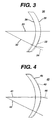
FIG. 3 is a magnified, cross-sectional view of a prior art progressive addition lens of Example 1. -
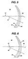
FIG. 4 is a magnified, cross-sectional view of the progressive addition lens ofFig. 3 of Example 1 into which prism power was added. -
Fig. 5 is a magnified, cross-sectional view of a progressive addition lens into which a uniform prism power was added at the interface. -
Fig. 6 is a progressive addition lens into which a graduated prism power was added at the interface. - The present invention provides lenses, as well as methods for their design and production, in which prism power is introduced into the lens. This added prism power overcomes, in whole or in part, the adverse image quality effect of the lens' unprescribed prism power.
- In one embodiment, the invention provides a progressive addition lens comprising, consisting essentially of, and consisting of an add power, a near vision zone vertical prism having a power and a base, and a vertical prism having a power and a base added to substantially the whole lens, wherein the added vertical prism base is opposite in direction to the near vision zone vertical prism base and the added vertical prism power is equal to about 0.25 percent of the add power.
- By "progressive addition lens " is meant a lens having at least one progressive addition surface. A "progressive addition surface" is a continuous, aspheric surface having distance and near viewing or vision zones, and a zone of increasing dioptric power connecting the distance and near zones. By "add power" is meant the amount of dioptric power difference between the near and distance vision zones of the progressive addition lens.
- In another embodiment, the invention provides a pair of progressive addition lens, comprising, consisting essentially of, and consisting of: a.) a first lens comprising, consisting essentially of, and consisting of a first add power, a first near vision zone vertical prism having a power and a base, and a first vertical prism having a power and a base added to substantially the whole lens; b.) a second lens comprising, consisting essentially of, and consisting of a second add power, a second near vision zone vertical prism having a power and a base, and a second vertical prism having a power and a base added to substantially the whole lens; wherein the first and second added prism base each are opposite in direction to the near vision zone vertical prism base to which it is added, the added vertical prisms each is equal to about 0.25 percent of the add power of the lens to which it is added, and there is a difference between the vertical prism at any point on the first lens and a corresponding point on the second lens equal to or less than about 0.5 diopters.
- It is a discovery of the invention that a the continuous change in power of the progressive addition lens from the distance to the near vision zone introduces vertical prism into the lens, the introduced prism varying in power corresponding to the power change from the lens' fitting point to the near vision zone. The power and direction of this vertical prism is dependent on the distance and near vision zone spherical powers of the lens.
- Typically, the prism will be either base up or base down. By "base up" is meant that the base of the prism lies in the direction of 90 degrees relative to the lens surface. By "base down" is meant that the base of the prism lies in the direction of 270 degrees relative to the lens surface. For positive spherical powers in the near vision zone, the vertical prism will be a base up prism and for a negative spherical power, the prism will be a base down prism. The effect of the base up prism is to curve and elongate the image being viewed by the lens wearer. Base down prism results in a curving of the image and a shifting upwardly of the image. Thus, the unprescribed prism inherent in a progressive addition lens near vision zone results in a reduced image quality for the lens wearer.
- It is another discovery of the image that the image quality of a progressive addition lens may be improved by addition of vertical prism to substantially the entire lens. The added prism is of a base direction that is opposite to that of the unprescribed vertical prism inherent in the near vision zone of the lens. Because vertical prism is added to substantially the entire lens, the added prism power must be limited to that amount that the lens wearer can tolerate without a substantial reduction of visual acuity in the distance viewing zone. Typically, more than one line loss of visual acuity, as measured using a visual acuity chart, is not well tolerated by the lens wearer. Therefore, preferably the amount of added vertical prism power is equal to about 0.25 percent of the lens' add power. More preferably, in a pair of lenses to be worn, the amount of added prism power is about equal in both lenses worn by the lens wearer. Most preferably, the amount of prism added to a pair of lenses is such that the vertical prism at any point on the right eye lens is different from that of corresponding point on the left eye lens by an amount equal to or less than about 0.5 diopters.
- The lenses of the invention may be fabricated by any convenient means and constructed of any known material suitable for production of ophthalmic lenses. Suitable materials include, without limitation, polycarbonate, allyl diglycol, polymethacrylate, and the like. Such materials are either commercially available or methods for their production are known. Further, the lenses may be produced by any conventional lens fabrication technique including, without limitation grinding, whole lens casting, molding, thermoforming, laminating, surface casting, or combinations thereof. Casting may be carried out by any means, but preferably is performed by surface casting including, without limitation, as disclosed in United States Patent Nos.
5,147,585 ,5,178,800 ,5,219,497 ,5,316,702 ,5,358,672 ,5,480,600 ,5,512,371 ,5,531,940 ,5,702,819 , and5,793,465 . - Addition of vertical prism power into a lens may be accomplished using a variety of methods. The particular method used will depend upon the method desired to be used in manufacturing the lens. For example, for lenses in which surfacing is used to produce one or more of the lens surfaces, the added vertical prism power may be incorporated into the lens through the surfacing process, for instance and without limitation by using offset blocking techniques. As an alternative method, in lenses in which one or more of the surfaces, or the entire lens is cast, the molds used to cast the lens or surface may be tilted so as to add the vertical prism power. The power of the vertical prism added intro the lens by such tilting will be approximately equal to the tilt of the mold surface to the preform surface. For example, one degree of tilt will equal about 1 diopter of added prism power. The direction of the tilt will determine whether the prism is base up or base down.
- In
Fig.1 is shownprogressive addition lens 10 of the prior art having the lens add power on the convex surface. Thesolid lines dotted line 13 indicates the shape of a lens with zero add power (single vision lens) and thedotted line 14 shows the difference in the ray trace between the progressive and single vision lens.Fig. 2 shows alens 20 that is a progressive addition lens with the add power on the convex surface. Dottedline 23 depicts the shape of the lens absent any added prism.Solid lines lens 20 with the convex surface of the lens tilted to produce base down prism. The resultant shape of the lens and the ray traces 25 and 26 show how the objects viewed through the lens appear largely unshifted due to the lower unprescribed prism in the near vision zone. - In a preferred embodiment, an optical preform is used and onto at least one preform's surfaces is cast one or more layers. By "optical preform" is meant a shaped, optically transparent article capable of refracting light and possessing a convex and a concave surface, which article is suitable for use in producing a spectacle lens. Each of the optical preform and cast layer refractive powers may be a portion or all of the distance vision, near vision, intermediate vision, or cylinder refractive power, of the finished lens to be formed, or combinations thereof. Preferably, at least one surface of the optical preform is a progressive addition surface and the cast layer forms an additional progressive surface, most preferably formed on the preform's front surface.
- Positioning of a mold and a preform so as to add the desired vertical prism power may be accomplished by use of any convenient positioning means such as a gimbal holder, a gripper, a vacuum gripper, or the like and combinations thereof. Preferably, positioning is accomplished by placing the mold, using positioning means such as suction, in a fixture capable of gimbaling action. The required mold displacement and tilt may be accomplished by any conventional displacement means, including, without limitation, servo motors.
- Once the desired mold-preform orientation is achieved material for forming the cast layer is dispensed into the mold and cured to form the cast layer. Suitable materials for use in the process include, without limitation, those disclosed in United States Patent No.
5,470,592 , incorporated in its entirety herein by reference. Additional suitable monomers include, without limitation, allyl and bis(allyl) carbonates, such as diethylene glycol bis(allyl) carbonate, bisphenol A diallyl carbonate, and the like, acrylic acid, multi-finctional acrylates and methacrylates, such as ethylene glycol diacrylate, tetraethylene glycol diacrylate, tripropylene glycol diacrylate, trimethylolpropane triacrylate, tetrahydrofurfuryl methacrylate, tetrahydrofurfuryl acrylate, hexanediolmethacrylate, methyl methacrylate, butyl methacrylate, propyl methacrylate, penterythritol tetraacrylate, urethane acrylates and methacrylates, styrene and styrene derivatives such as divinyl benzene, 4-vinyl anisole, various esters or maleic and itaconic acids, methacrylic and acrylic
anhydrides and the like, and combinations thereof. Such monomers are commercially available or methods for their production are known. Materials
suitable for use for the preform are those above-listed for use as spectacle lens material. - Curing of the dispensed material may take place by any conventional means including, without limitation, thermal cure, radiation cure, visible light cure, and combinations thereof. Preferably, ultra-violet cure is used, more preferably a two-stage UV cure in which the mold is exposed to low intensity and then high intensity ultraviolet light.
- In another embodiment, the prism is introduced at the interface of two layers of a lens, each layer preferably being of a different refractive index. The amount of the prism may be one of constant over the entire lens area, have a constant value above the x-axis, have a different constant value below the x-axis, have a blended discontinuity across the x-axis, gradually change in a smooth, monotonic manner from the fitting point to the near vision zone of the lens, or combinations thereof. In embodiments in which the magnitude, or amount, of the added prism changes from the fitting point to the near vision zone, the change must be gradual so as to avoid
introduction of unwanted astigmatism into the progressive addition channel. The magnitude of the added prism must take into account the refractive index difference between the two layers according to standard optical principles. Placing the prism at an internal interface is advantageous in that it permits independent control of the amount of prism in the distance and near viewing zones and simplifies the lens' manufacture. - The invention will be clarified further by a consideration of the following, nonlimiting examples.
- In
Fig. 3 is shown aprogressive addition lens 30 having a portion of the total lens add power on theconvex surface 35 and another portion on theconcave surface 36. The lens of this example was formed by casting a progressive addition surface onto the convex surface of an optical preform. A lens having a total add power of 2.25 diopters was produced with the concave surface having an add power of 0.75 diopters and the convex surface an add power of 1.50 diopters. A lens with a total add power of 1.50 diopters was produced with the concave surface having an add power of 0.75 diopters and the convex surface an add power of 0.75 diopters. Thesolid lines Dotted line 33 depicts the shape of the lens in the case that the lens is a single vision lens and dottedline 34 shift in the ray trace for the single vision lens. Table 1 shows the horizontal and vertical prism powers of lenses such aslens 30 without added prism. For the 2.25 diopter add power lenses the unprescribed vertical prism in the near zone ranges between 0.65 and 1.12 base up prism diopters.
For the 1.50 diopter add power lenses the unprescribed vertical prism in the near zone ranges between 0.49 and 0.59 base up prism diopters.Table 1 Add Power; Left or Right Near Vision Zone Unprescribed Horizontal Prism; Direction Near Vision Zone Unprescribed Vertical Prism; Direction Distance Vision Zone Unprescribed Horizontal Prism; Direction Distance Vision Zone Unprescribed Vertical Prism; Direction 2.25 diopters 0.05 D 1.12D 0.12 D 092D Right out up in down 2.25 diopters 0.06 D 0.65 D 0.12 D 0.92 D Left in up in down 2.25 diopters 0.10D 1.06 D 0.14 D 0.57 D Right in up out down 2.25 diopters 0.03 D 0.78 D 0.04 D 0.59 D Left in up out down 1.50 diopters 0.18 D 0.49 D 0.16D 0.35 D Right in up out down 1.50 diopters 0.14D 0.50 D 0.04 D 0.59 D Left in up out down 1.50 diopters 0.05 D 0.59 D 0.45 D 0.37 D Right in up in down 1.50 diopters 0.15 D 0.57 D 0.32 D 0.45 D Left in up out down -
Fig. 4 showsprogressive addition lenses 40 produced withconvex surface 45 tilted to produce base down prism. These lenses were formed by casting a progressive addition surface onto an optical preform. Vertical prism was added to the lenses by tilting the glass mold used to cast the progressive addition surface B degrees in relation to the preform about the preform's x axis, given by the formula: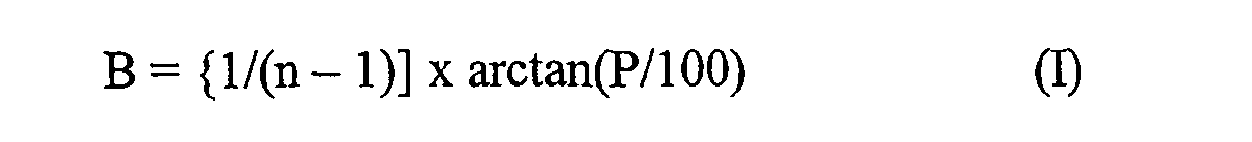
where n is the refractive index of the cast layer and P is the introduced prism.
A suitable casting resin was then added and the cured to form the lenses shown. The amount of vertical prism added was equal to half of the add power. For the 2.25 diopter add power lenses, approximately 1.12 diopters of base down prism were added. For the 1.50 diopter add power lenses, approximately 0.75 of base down prism was added.Solid lines Dotted line 44 depicts the ray trace absent addition of the prism. - In Table 2 is shown the lenses of Table 1 into which vertical prism power was added. As can be seen by a comparison of the tables, the near vision zone vertical prism power is reduced by the added prism power.
Table 2 Add Power; Left or Right Near Vision Zone Unprescribed Horizontal Prism; Direction Near Vision Zone Vertical Prism; Direction Distance Vision Zone Unprescribed Horizontal Prism; Direction Distance Vision Zone Vertical Prism; Direction 2.25 diopters 0.05 D 0.01 D 0.12 D 2.04 D Right out down in down 2.25 diopters 0.06 D 0.47 D 0.12 D 2.04 D Left in down in down 2.25 diopters 0.10 D 0.06 D 0.14 D 1.69 D Right in down out down 2.25 diopters 0.03 D 0.34 D 0.04 D 1.71 D Left in down out down 1.50 diopters 0.18 D 0.26 D 0.16 D 1.10 D Right in down out down 1.50 diopters 0.14 D 0.25 D 0.04 D 1.34 D Left in down out down 1.50 diopters 0.05 D 0.16 D 0.45 D 1.12 D Right in down in down 1.50 diopters 0.15D 0.18 D 0.32 D 1.20 D Left in down out down - In
Fig. 5 is depicted alens 50 in which there is introduction of a uniform magnitude of base down prism at an interface of twosurfaces 54 and 55 of the lens, one surface being made from a material of a refractive index of 1.60 and the other of 1.50. The convex surface 54 of the lens has a distance zone curvature of 6.00 diopters and near zone curvature of 7.00 diopters. Theconcave surface 55 distance zone has a curvature of 6.00 diopters and a near zone curvature of 5.00 diopters. The lens' distance power is 0.00 diopters and the add power is 2.00 diopters. The curvature of theinterface 56 is 6.00 diopters and is tilted, relative to the convex surface by 6 degrees (D) to produce base down prism (P) over the whole lens of:
Solid lines line 53 depicts the ray trace absent the added prism. - In
Fig. 6 is illustrated alens 60 into which there is introduction of a gradually increasing magnitude of base down prism at the interface between twosurfaces convex surface 64 of the lens has a distance zone curvature of 6.00 diopters and a near zone curvature of 7.00 diopters. Theconcave surface 65 distance zone curvature is 6.00 diopters and it has a near zone curvature of 5.00 diopters. The lens' distance power is 0.00 diopters and the add power is 2.00 diopters. The curvature of theinterface 66 in the distance zone from the fitting point and above (y > 0 mm) is 6.00 diopters and is parallel to the convex surface in the zone. This introduces no prism at the fitting point. The curvature below the top of the near zone (y < -15 mm) is 6.00 diopters and tilted, relative to the convex surface, by 6 degrees introducing base down prism in the near zone of :
The interface curvature between the fitting point and the top of the near zone (o > y > - 15 mm) is smoothly blended to the curvature above and below these coordinates in such a manner as to minimize visual disturbances.Solid lines line 63 depicts the ray trace absent the added prism.
Claims (6)
- A progressive addition lens comprising at least one progressive addition surface, with distance and near vision zone and a zone of increasing dioptric power connecting the distance and near vision zones, an unprescribed vertical prism in the progressive addition lens near vision zone characterised in that a vertical prism added to the entire lens which base direction is opposite to that of the unprescribed vertical prism in the near vision zone of the lens.
- The lens of claim 1, wherein the lens further comprises an optical preform comprising a progressive addition surface.
- The lens of claim 2, further comprising a progressive addition surface cast onto the optical preform.
- A 2,25 diopters lens according to claim 1 with 1,12 diopters of base down prism addition.
- A 1,50 diopter lens according to claim 1 with 0,75 diopter of base down prism addition.
- A method for manufacturing a progressive addition lens comprising at least one progressive addition surface, with distance and near vision, zone and a zone of increasing dioptric power connecting the distance and near vision zones, an unprescribed vertical prism in the progressive addition lens near vision zone and a vertical prism added to the entire lens which base direction is opposite to that of the unprescribed vertical prism in the near vision zone of the lens where at least one surface is cast musing molds, and said molds are tilted so as to add the vertical prism power.
Applications Claiming Priority (3)
| Application Number | Priority Date | Filing Date | Title |
|---|---|---|---|
| US844910 | 1986-03-26 | ||
| US09/844,910 US6505934B1 (en) | 2001-04-27 | 2001-04-27 | Progressive addition lenses with prism power added to improve wearer comfort |
| PCT/US2002/013421 WO2002088832A2 (en) | 2001-04-27 | 2002-04-26 | Progressive addition lenses with prism power added to improve wearer comfort |
Publications (2)
| Publication Number | Publication Date |
|---|---|
| EP1412806A2 EP1412806A2 (en) | 2004-04-28 |
| EP1412806B1 true EP1412806B1 (en) | 2008-10-08 |
Family
ID=25293942
Family Applications (1)
| Application Number | Title | Priority Date | Filing Date |
|---|---|---|---|
| EP02734073A Expired - Lifetime EP1412806B1 (en) | 2001-04-27 | 2002-04-26 | Progressive addition lenses with prism power added to improve wearer comfort |
Country Status (16)
| Country | Link |
|---|---|
| US (1) | US6505934B1 (en) |
| EP (1) | EP1412806B1 (en) |
| JP (1) | JP4277977B2 (en) |
| KR (1) | KR100978799B1 (en) |
| CN (2) | CN1585909A (en) |
| AT (1) | ATE410714T1 (en) |
| AU (1) | AU2002305263B2 (en) |
| BR (1) | BR0209260A (en) |
| CA (1) | CA2445879C (en) |
| DE (1) | DE60229258D1 (en) |
| IL (2) | IL158603A0 (en) |
| MX (1) | MXPA03009852A (en) |
| MY (1) | MY122872A (en) |
| RU (1) | RU2282225C2 (en) |
| TW (1) | TW594099B (en) |
| WO (1) | WO2002088832A2 (en) |
Cited By (1)
| Publication number | Priority date | Publication date | Assignee | Title |
|---|---|---|---|---|
| DE102010007267A1 (en) | 2010-02-08 | 2011-08-11 | Carl Zeiss Vision GmbH, 73430 | Lens element with improved prismatic effect |
Families Citing this family (28)
| Publication number | Priority date | Publication date | Assignee | Title |
|---|---|---|---|---|
| JP4164550B2 (en) * | 2001-10-12 | 2008-10-15 | セイコーオプティカルプロダクツ株式会社 | Progressive power spectacle lens |
| FR2850763B1 (en) * | 2003-02-03 | 2005-07-01 | Essilor Int | APHTHALMIC LENS WITH PROGRESSIVE ADDITION OF POWER AND PRISM |
| JP3882764B2 (en) * | 2003-02-19 | 2007-02-21 | セイコーエプソン株式会社 | Progressive power lens |
| JP3582527B1 (en) * | 2003-04-10 | 2004-10-27 | セイコーエプソン株式会社 | Progressive power lens and manufacturing method |
| US7104647B2 (en) * | 2005-02-03 | 2006-09-12 | Krall Jeffrey P | Multi-focal ophthalmic lens with base in prism |
| US7258437B2 (en) * | 2005-09-07 | 2007-08-21 | Transitions Optical, Inc. | Photochromic multifocal optical article |
| ES2483171T3 (en) * | 2007-01-25 | 2014-08-05 | Rodenstock Gmbh | Reference points for ortho position |
| US7883206B2 (en) | 2007-03-07 | 2011-02-08 | Pixeloptics, Inc. | Multifocal lens having a progressive optical power region and a discontinuity |
| US20080273169A1 (en) * | 2007-03-29 | 2008-11-06 | Blum Ronald D | Multifocal Lens Having a Progressive Optical Power Region and a Discontinuity |
| EP2202561A1 (en) * | 2008-12-24 | 2010-06-30 | Essilor International (Compagnie Générale D'Optique) | A lens customizing method |
| AU2013202323A1 (en) * | 2012-02-21 | 2013-09-05 | Queensland University Of Technology | Slowing myopia progression and/or the treatment or prevention of myopia or a disease or condition associated with myopia |
| EP2772793B1 (en) * | 2013-03-01 | 2015-09-16 | ESSILOR INTERNATIONAL (Compagnie Générale d'Optique) | Method for optimizing the postural prism of an ophthalmic lens |
| US9618774B2 (en) * | 2014-02-10 | 2017-04-11 | Shamir Optical Industry Ltd. | Quasi progressive lenses for eyewear |
| US10048511B2 (en) | 2016-10-08 | 2018-08-14 | eyeBrain, Medical, Inc. | Eye-strain reducing lens |
| US10048512B2 (en) | 2016-10-08 | 2018-08-14 | eyeBrain, Medical, Inc. | Low-convergence spectacles |
| US10338409B2 (en) | 2016-10-09 | 2019-07-02 | eyeBrain Medical, Inc. | Lens with off-axis curvature center |
| US20180196281A1 (en) | 2017-01-06 | 2018-07-12 | eyeBrain Medical, Inc. | Prismatic contact lens |
| US11589745B2 (en) | 2017-09-05 | 2023-02-28 | Neurolens, Inc. | Method and system for measuring binocular alignment |
| US12569135B2 (en) | 2017-09-05 | 2026-03-10 | Newton, Inc. | Headset-based system for measuring binocular alignment |
| US10420467B2 (en) | 2017-09-05 | 2019-09-24 | eyeBrain Medical, Inc. | Method and system for measuring binocular alignment |
| US12114930B2 (en) | 2017-09-05 | 2024-10-15 | Neurolens, Inc. | System for measuring binocular alignment with adjustable displays and eye trackers |
| US10921614B2 (en) | 2017-12-31 | 2021-02-16 | Neurolens, Inc. | Low-convergence negative power spectacles |
| US11360329B2 (en) | 2017-12-31 | 2022-06-14 | Neurolens, Inc. | Negative power eye-strain reducing lens |
| US10908434B2 (en) | 2018-01-01 | 2021-02-02 | Neurolens, Inc. | Negative power lens with off-axis curvature center |
| KR101879359B1 (en) * | 2018-01-05 | 2018-07-17 | 한미스위스광학 주식회사 | Multi-focussing lens and Manufacturing Method |
| US20200073146A1 (en) * | 2018-09-05 | 2020-03-05 | Jan Hoogland | Generic Reading Glasses with Convergence Assistance |
| CA3183684A1 (en) | 2020-06-01 | 2021-12-08 | Icares Medicus, Inc. | Double-sided aspheric diffractive multifocal lens, manufacture, and uses thereof |
| WO2022118991A1 (en) * | 2020-12-01 | 2022-06-09 | 한미스위스광학 주식회사 | Customized bi-aspherical lens and manufacturing method therefor |
Citations (1)
| Publication number | Priority date | Publication date | Assignee | Title |
|---|---|---|---|---|
| US6019470A (en) * | 1995-11-24 | 2000-02-01 | Seiko Epson Corporation | Progressive multifocal lens and manufacturing method of eyeglass lens and progressive multifocal lens |
Family Cites Families (15)
| Publication number | Priority date | Publication date | Assignee | Title |
|---|---|---|---|---|
| US1393853A (en) | 1919-06-24 | 1921-10-18 | American Optical Corp | Lens |
| GB186641A (en) * | 1921-03-31 | 1922-10-02 | Edgar Derry Tillyer | Improvements in lenses |
| SU5936A1 (en) * | 1926-09-10 | 1928-07-31 | Карл Цейсс | Eye lens system |
| US2442849A (en) | 1944-07-11 | 1948-06-08 | Harry Langsam | Ophthalmic lens |
| US3507565A (en) * | 1967-02-21 | 1970-04-21 | Optical Res & Dev Corp | Variable-power lens and system |
| DE2814916C3 (en) | 1978-04-06 | 1982-01-07 | Optische Werke G. Rodenstock, 8000 München | Spectacle lens with a progression area located between the far part and the near part |
| US4606626A (en) | 1982-12-13 | 1986-08-19 | Seiko Epson Corporation | Progressive multifocal ophthalmic lenses with prism for correcting chromatic aberration |
| US4981342A (en) * | 1987-09-24 | 1991-01-01 | Allergan Inc. | Multifocal birefringent lens system |
| US5219497A (en) * | 1987-10-30 | 1993-06-15 | Innotech, Inc. | Method for manufacturing lenses using thin coatings |
| JP3273783B2 (en) * | 1989-07-17 | 2002-04-15 | オプティッシェ.ウエルケ.ゲー.ローデンストック | Progressive lenses for spectacles with positive remote visual power |
| WO1992012452A1 (en) * | 1990-12-27 | 1992-07-23 | Seiko Epson Corporation | Progressive lens |
| US5689324A (en) | 1992-08-18 | 1997-11-18 | Q2100, Inc. | Progressive lens |
| US5480600A (en) * | 1993-03-24 | 1996-01-02 | Innotech, Inc. | Method for manufacturing thin progressive addition lenses |
| US6086203A (en) * | 1998-09-03 | 2000-07-11 | Johnson & Johnson Vision Care, Inc. | Progressive addition lenses |
| IL132466A (en) * | 1999-05-20 | 2002-09-12 | Johnson & Johnson Vision Care | Methods for producing progressive addition lenses |
-
2001
- 2001-04-27 US US09/844,910 patent/US6505934B1/en not_active Expired - Lifetime
-
2002
- 2002-04-26 AU AU2002305263A patent/AU2002305263B2/en not_active Ceased
- 2002-04-26 IL IL15860302A patent/IL158603A0/en unknown
- 2002-04-26 RU RU2003134370/28A patent/RU2282225C2/en active
- 2002-04-26 DE DE60229258T patent/DE60229258D1/en not_active Expired - Lifetime
- 2002-04-26 BR BR0209260-3A patent/BR0209260A/en not_active Application Discontinuation
- 2002-04-26 CN CNA028129261A patent/CN1585909A/en active Pending
- 2002-04-26 EP EP02734073A patent/EP1412806B1/en not_active Expired - Lifetime
- 2002-04-26 JP JP2002586072A patent/JP4277977B2/en not_active Expired - Fee Related
- 2002-04-26 AT AT02734073T patent/ATE410714T1/en not_active IP Right Cessation
- 2002-04-26 CA CA2445879A patent/CA2445879C/en not_active Expired - Fee Related
- 2002-04-26 MY MYPI20021537A patent/MY122872A/en unknown
- 2002-04-26 CN CN2007101013348A patent/CN101082705B/en not_active Expired - Lifetime
- 2002-04-26 MX MXPA03009852A patent/MXPA03009852A/en active IP Right Grant
- 2002-04-26 WO PCT/US2002/013421 patent/WO2002088832A2/en not_active Ceased
- 2002-04-26 TW TW091108612A patent/TW594099B/en not_active IP Right Cessation
- 2002-04-26 KR KR1020037014085A patent/KR100978799B1/en not_active Expired - Fee Related
-
2003
- 2003-10-26 IL IL158603A patent/IL158603A/en not_active IP Right Cessation
Patent Citations (1)
| Publication number | Priority date | Publication date | Assignee | Title |
|---|---|---|---|---|
| US6019470A (en) * | 1995-11-24 | 2000-02-01 | Seiko Epson Corporation | Progressive multifocal lens and manufacturing method of eyeglass lens and progressive multifocal lens |
Cited By (3)
| Publication number | Priority date | Publication date | Assignee | Title |
|---|---|---|---|---|
| DE102010007267A1 (en) | 2010-02-08 | 2011-08-11 | Carl Zeiss Vision GmbH, 73430 | Lens element with improved prismatic effect |
| EP2363743A1 (en) | 2010-02-08 | 2011-09-07 | Carl Zeiss Vision GmbH | Lens element with improved prismatic effect |
| US8425034B2 (en) | 2010-02-08 | 2013-04-23 | Carl Zeiss Vision International Gmbh | Lens element with improved prismatic power |
Also Published As
| Publication number | Publication date |
|---|---|
| CN101082705A (en) | 2007-12-05 |
| WO2002088832A2 (en) | 2002-11-07 |
| KR20040030602A (en) | 2004-04-09 |
| MXPA03009852A (en) | 2004-12-06 |
| MY122872A (en) | 2006-05-31 |
| EP1412806A2 (en) | 2004-04-28 |
| BR0209260A (en) | 2005-02-01 |
| KR100978799B1 (en) | 2010-08-30 |
| TW594099B (en) | 2004-06-21 |
| CA2445879C (en) | 2010-09-21 |
| CN1585909A (en) | 2005-02-23 |
| ATE410714T1 (en) | 2008-10-15 |
| JP2005503576A (en) | 2005-02-03 |
| US6505934B1 (en) | 2003-01-14 |
| CN101082705B (en) | 2010-06-30 |
| WO2002088832A3 (en) | 2004-02-26 |
| IL158603A0 (en) | 2004-05-12 |
| DE60229258D1 (en) | 2008-11-20 |
| RU2282225C2 (en) | 2006-08-20 |
| RU2003134370A (en) | 2005-02-27 |
| CA2445879A1 (en) | 2002-11-07 |
| JP4277977B2 (en) | 2009-06-10 |
| AU2002305263B2 (en) | 2006-11-23 |
| IL158603A (en) | 2010-04-29 |
Similar Documents
| Publication | Publication Date | Title |
|---|---|---|
| EP1412806B1 (en) | Progressive addition lenses with prism power added to improve wearer comfort | |
| AU2002305263A1 (en) | Progressive addition lenses with prism power added to improve wearer comfort | |
| KR100629406B1 (en) | Progressive addition lenses and a process for preparing the same | |
| AU763372B2 (en) | Progressive addition lenses having regressive surfaces | |
| CN100399107C (en) | Improved Visual Simple Lens | |
| JP4223290B2 (en) | Progressive focus lens | |
| CN1146743C (en) | Progressive addition lenses with varing power profiles | |
| AU732021B2 (en) | Improved ophthalmic lens | |
| CA2375162C (en) | Progressive lens | |
| US6886938B1 (en) | Progressive addition lenses with an additional zone | |
| JP4674346B2 (en) | Progressive Addition Lens | |
| EP1019779A4 (en) | IMPROVED PROGRESSIVE GLASS | |
| US6155681A (en) | Progressive lens | |
| AU720997B2 (en) | Progressive lens | |
| MXPA98008839A (en) | Progress lens | |
| HK1019092B (en) | Improved single vision lenses | |
| HK1026743A (en) | Progressive addition lenses having regressive surfaces |
Legal Events
| Date | Code | Title | Description |
|---|---|---|---|
| PUAI | Public reference made under article 153(3) epc to a published international application that has entered the european phase |
Free format text: ORIGINAL CODE: 0009012 |
|
| 17P | Request for examination filed |
Effective date: 20031126 |
|
| AK | Designated contracting states |
Kind code of ref document: A2 Designated state(s): AT BE CH CY DE DK ES FI FR GB GR IE IT LI LU MC NL PT SE TR |
|
| AX | Request for extension of the european patent |
Extension state: AL LT LV MK RO SI |
|
| REG | Reference to a national code |
Ref country code: HK Ref legal event code: DE Ref document number: 1065116 Country of ref document: HK |
|
| 17Q | First examination report despatched |
Effective date: 20050228 |
|
| RAP1 | Party data changed (applicant data changed or rights of an application transferred) |
Owner name: ESSILOR INTERNATIONAL(COMPAGNIE GENERALE D'OPTIQUE |
|
| GRAP | Despatch of communication of intention to grant a patent |
Free format text: ORIGINAL CODE: EPIDOSNIGR1 |
|
| GRAS | Grant fee paid |
Free format text: ORIGINAL CODE: EPIDOSNIGR3 |
|
| GRAA | (expected) grant |
Free format text: ORIGINAL CODE: 0009210 |
|
| AK | Designated contracting states |
Kind code of ref document: B1 Designated state(s): AT BE CH CY DE DK ES FI FR GB GR IE IT LI LU MC NL PT SE TR |
|
| REG | Reference to a national code |
Ref country code: GB Ref legal event code: FG4D |
|
| REG | Reference to a national code |
Ref country code: CH Ref legal event code: EP |
|
| REG | Reference to a national code |
Ref country code: IE Ref legal event code: FG4D |
|
| REF | Corresponds to: |
Ref document number: 60229258 Country of ref document: DE Date of ref document: 20081120 Kind code of ref document: P |
|
| PG25 | Lapsed in a contracting state [announced via postgrant information from national office to epo] |
Ref country code: AT Free format text: LAPSE BECAUSE OF FAILURE TO SUBMIT A TRANSLATION OF THE DESCRIPTION OR TO PAY THE FEE WITHIN THE PRESCRIBED TIME-LIMIT Effective date: 20081008 Ref country code: ES Free format text: LAPSE BECAUSE OF FAILURE TO SUBMIT A TRANSLATION OF THE DESCRIPTION OR TO PAY THE FEE WITHIN THE PRESCRIBED TIME-LIMIT Effective date: 20090119 |
|
| PG25 | Lapsed in a contracting state [announced via postgrant information from national office to epo] |
Ref country code: PT Free format text: LAPSE BECAUSE OF FAILURE TO SUBMIT A TRANSLATION OF THE DESCRIPTION OR TO PAY THE FEE WITHIN THE PRESCRIBED TIME-LIMIT Effective date: 20090218 Ref country code: FI Free format text: LAPSE BECAUSE OF FAILURE TO SUBMIT A TRANSLATION OF THE DESCRIPTION OR TO PAY THE FEE WITHIN THE PRESCRIBED TIME-LIMIT Effective date: 20081008 |
|
| PG25 | Lapsed in a contracting state [announced via postgrant information from national office to epo] |
Ref country code: DK Free format text: LAPSE BECAUSE OF FAILURE TO SUBMIT A TRANSLATION OF THE DESCRIPTION OR TO PAY THE FEE WITHIN THE PRESCRIBED TIME-LIMIT Effective date: 20081008 Ref country code: BE Free format text: LAPSE BECAUSE OF FAILURE TO SUBMIT A TRANSLATION OF THE DESCRIPTION OR TO PAY THE FEE WITHIN THE PRESCRIBED TIME-LIMIT Effective date: 20081008 |
|
| PLBE | No opposition filed within time limit |
Free format text: ORIGINAL CODE: 0009261 |
|
| STAA | Information on the status of an ep patent application or granted ep patent |
Free format text: STATUS: NO OPPOSITION FILED WITHIN TIME LIMIT |
|
| PG25 | Lapsed in a contracting state [announced via postgrant information from national office to epo] |
Ref country code: SE Free format text: LAPSE BECAUSE OF FAILURE TO SUBMIT A TRANSLATION OF THE DESCRIPTION OR TO PAY THE FEE WITHIN THE PRESCRIBED TIME-LIMIT Effective date: 20090108 Ref country code: IT Free format text: LAPSE BECAUSE OF FAILURE TO SUBMIT A TRANSLATION OF THE DESCRIPTION OR TO PAY THE FEE WITHIN THE PRESCRIBED TIME-LIMIT Effective date: 20081008 |
|
| 26N | No opposition filed |
Effective date: 20090709 |
|
| REG | Reference to a national code |
Ref country code: CH Ref legal event code: PL |
|
| PG25 | Lapsed in a contracting state [announced via postgrant information from national office to epo] |
Ref country code: LI Free format text: LAPSE BECAUSE OF NON-PAYMENT OF DUE FEES Effective date: 20090430 Ref country code: CH Free format text: LAPSE BECAUSE OF NON-PAYMENT OF DUE FEES Effective date: 20090430 |
|
| PG25 | Lapsed in a contracting state [announced via postgrant information from national office to epo] |
Ref country code: IE Free format text: LAPSE BECAUSE OF NON-PAYMENT OF DUE FEES Effective date: 20090426 Ref country code: MC Free format text: LAPSE BECAUSE OF NON-PAYMENT OF DUE FEES Effective date: 20090430 |
|
| PG25 | Lapsed in a contracting state [announced via postgrant information from national office to epo] |
Ref country code: GR Free format text: LAPSE BECAUSE OF FAILURE TO SUBMIT A TRANSLATION OF THE DESCRIPTION OR TO PAY THE FEE WITHIN THE PRESCRIBED TIME-LIMIT Effective date: 20090109 |
|
| REG | Reference to a national code |
Ref country code: HK Ref legal event code: WD Ref document number: 1065116 Country of ref document: HK |
|
| PG25 | Lapsed in a contracting state [announced via postgrant information from national office to epo] |
Ref country code: LU Free format text: LAPSE BECAUSE OF NON-PAYMENT OF DUE FEES Effective date: 20090426 |
|
| PG25 | Lapsed in a contracting state [announced via postgrant information from national office to epo] |
Ref country code: TR Free format text: LAPSE BECAUSE OF FAILURE TO SUBMIT A TRANSLATION OF THE DESCRIPTION OR TO PAY THE FEE WITHIN THE PRESCRIBED TIME-LIMIT Effective date: 20081008 |
|
| PG25 | Lapsed in a contracting state [announced via postgrant information from national office to epo] |
Ref country code: CY Free format text: LAPSE BECAUSE OF FAILURE TO SUBMIT A TRANSLATION OF THE DESCRIPTION OR TO PAY THE FEE WITHIN THE PRESCRIBED TIME-LIMIT Effective date: 20081008 |
|
| PGFP | Annual fee paid to national office [announced via postgrant information from national office to epo] |
Ref country code: NL Payment date: 20140426 Year of fee payment: 13 |
|
| REG | Reference to a national code |
Ref country code: FR Ref legal event code: PLFP Year of fee payment: 14 |
|
| REG | Reference to a national code |
Ref country code: NL Ref legal event code: MM Effective date: 20150501 |
|
| PG25 | Lapsed in a contracting state [announced via postgrant information from national office to epo] |
Ref country code: NL Free format text: LAPSE BECAUSE OF NON-PAYMENT OF DUE FEES Effective date: 20150501 |
|
| REG | Reference to a national code |
Ref country code: FR Ref legal event code: PLFP Year of fee payment: 15 |
|
| REG | Reference to a national code |
Ref country code: FR Ref legal event code: PLFP Year of fee payment: 16 |
|
| REG | Reference to a national code |
Ref country code: DE Ref legal event code: R082 Ref document number: 60229258 Country of ref document: DE Representative=s name: ETL WABLAT & KOLLEGEN PATENT- UND RECHTSANWALT, DE Ref country code: DE Ref legal event code: R082 Ref document number: 60229258 Country of ref document: DE Representative=s name: ETL IP PATENT- UND RECHTSANWALTSGESELLSCHAFT M, DE Ref country code: DE Ref legal event code: R082 Ref document number: 60229258 Country of ref document: DE Representative=s name: WABLAT LANGE KARTHAUS ANWALTSSOZIETAET, DE Ref country code: DE Ref legal event code: R081 Ref document number: 60229258 Country of ref document: DE Owner name: ESSILOR INTERNATIONAL, FR Free format text: FORMER OWNER: ESSILOR INTERNATIONAL (COMPAGNIE GENERALE D'OPTIQUE), CHARENTON-LE-PONT, FR |
|
| REG | Reference to a national code |
Ref country code: FR Ref legal event code: PLFP Year of fee payment: 17 |
|
| REG | Reference to a national code |
Ref country code: GB Ref legal event code: 732E Free format text: REGISTERED BETWEEN 20180517 AND 20180523 |
|
| REG | Reference to a national code |
Ref country code: FR Ref legal event code: TP Owner name: ESSILOR INTERNATIONAL, FR Effective date: 20180601 |
|
| REG | Reference to a national code |
Ref country code: DE Ref legal event code: R082 Ref document number: 60229258 Country of ref document: DE Representative=s name: ETL WABLAT & KOLLEGEN PATENT- UND RECHTSANWALT, DE Ref country code: DE Ref legal event code: R082 Ref document number: 60229258 Country of ref document: DE Representative=s name: ETL IP PATENT- UND RECHTSANWALTSGESELLSCHAFT M, DE |
|
| REG | Reference to a national code |
Ref country code: DE Ref legal event code: R082 Ref document number: 60229258 Country of ref document: DE Representative=s name: ETL IP PATENT- UND RECHTSANWALTSGESELLSCHAFT M, DE |
|
| PGFP | Annual fee paid to national office [announced via postgrant information from national office to epo] |
Ref country code: FR Payment date: 20210426 Year of fee payment: 20 Ref country code: DE Payment date: 20210428 Year of fee payment: 20 |
|
| PGFP | Annual fee paid to national office [announced via postgrant information from national office to epo] |
Ref country code: GB Payment date: 20210427 Year of fee payment: 20 |
|
| REG | Reference to a national code |
Ref country code: DE Ref legal event code: R071 Ref document number: 60229258 Country of ref document: DE |
|
| REG | Reference to a national code |
Ref country code: GB Ref legal event code: PE20 Expiry date: 20220425 |
|
| PG25 | Lapsed in a contracting state [announced via postgrant information from national office to epo] |
Ref country code: GB Free format text: LAPSE BECAUSE OF EXPIRATION OF PROTECTION Effective date: 20220425 |