EP1415527A1 - Verstelleinrichtung für ein bewegliches Element eines Erntevorsatzes - Google Patents
Verstelleinrichtung für ein bewegliches Element eines Erntevorsatzes Download PDFInfo
- Publication number
- EP1415527A1 EP1415527A1 EP03103547A EP03103547A EP1415527A1 EP 1415527 A1 EP1415527 A1 EP 1415527A1 EP 03103547 A EP03103547 A EP 03103547A EP 03103547 A EP03103547 A EP 03103547A EP 1415527 A1 EP1415527 A1 EP 1415527A1
- Authority
- EP
- European Patent Office
- Prior art keywords
- spring
- adjusting device
- transport
- forces
- header
- Prior art date
- Legal status (The legal status is an assumption and is not a legal conclusion. Google has not performed a legal analysis and makes no representation as to the accuracy of the status listed.)
- Granted
Links
Images


Classifications
-
- A—HUMAN NECESSITIES
- A01—AGRICULTURE; FORESTRY; ANIMAL HUSBANDRY; HUNTING; TRAPPING; FISHING
- A01D—HARVESTING; MOWING
- A01D41/00—Combines, i.e. harvesters or mowers combined with threshing devices
- A01D41/12—Details of combines
- A01D41/14—Mowing tables
- A01D41/144—Foldable headers
Definitions
- the invention relates to an adjusting device for a movable Element of a header, with an adjustment drive, which is set up, the element between a first position and a second position in which it is opposite the first position is raised.
- FIG. 1a Such a pivoting process is shown in the three parts of FIG. 1 shown.
- the one is rigid or swingable middle part 12, a on the left in the forward direction on the middle part 12 a horizontal and forward swivel axis 18 hinged left side part 14 and one on the right Side of the middle part 12 by a horizontal and in Forward pivot axis 18 hinged right Side part 16 assembled header 10 in its operating position shown in which the parts 12-16 horizontally are oriented to harvest plants from a field.
- Figure 1b are the side parts 14, 16 by about 115 ° Swivel axes 18 in an intermediate position inwards and upwards pivoted, while in Figure 1c by 180 ° inwards are pivoted and save space in their transport position lie above the middle part 12.
- the necessary for pivoting the side parts 14, 16 Swiveling forces are usually generated by hydraulic cylinders applied.
- the forces to be applied by the adjustment drive increase starting from the operating position, go through a maximum and then decrease.
- the one shown in Figure 1b Intermediate or equilibrium position is approximately one Equilibrium reached, d. H. the adjustment drive needs almost none Apply force to hold the side panels 14, 16.
- the adjustment drive In the further Swiveling act opposite forces, since now the No longer lift the side parts 14, 16, but only has to support. If the side parts 14, 16
- the adjustment drive must be brought back into the operating position Forces with equal amounts, but opposite Apply direction.
- the adjustment drives are sufficiently large dimension so that they also the force maxima shortly after Can record the beginning of the swivel movement.
- the object on which the invention is based is seen in an improved adjustment device for a header provide.
- the header comprises a movable element and one Actuator that is suitable between a first Position and a second position to move.
- the adjustment drive must therefore perform apply it against gravity from the first to the to spend second position. It is suggested the item by means of a spring in the direction of the second position biasing. As a result, the one to be applied by the adjustment drive Performance or power reduced.
- the adjustment drive can do that Swivel the element between the first and second position and / or move. It would also be conceivable instead to use a weight of the spring. Because of the lower mass the spring is usually more advantageous, although it is also quite Use cases where the use of a Weight makes sense.
- the adjustment drive can be smaller and cheaper be dimensioned and work faster than conventional ones Adjustment.
- the element is 90 ° behind can be swiveled into a transport position at the top.
- Cutting units that are made up of two halves.
- the invention can be advantageously used for such headers use as the for pivoting the elements (e.g. cutting unit halves) from the first position, the operating position, to up in the second position, the transport position, forces to be applied are reduced. Lowering against the The spring can be biased by gravity and / or by the adjustment drive acting in the opposite direction respectively.
- the element is the first Position moved over the second position into a third position, in which his focus is also below the location of the Center of gravity is in the second position.
- the adjustment drive must therefore also have an output in order to to move the element from the third to the second position.
- a spring provide the element from the third position towards biased towards the second position, in this case too to reduce the power to be provided by the adjustment drive.
- at the spring can be the same spring as that Element biased from the first to the second position (i.e. around a spring that is both compressible and expandable is) or a separate spring.
- Header in which the element is between an operating position (first position) via an intermediate position (second position) in the transport position (third position) can be moved.
- Examples are corn headers or corn headers with upwards and inside foldable side panels. If the swivel angle of the Element is greater than 90 ° when moving from Operating position in the transport position initially a force to Lifting the element against gravity. To Passing through the intermediate position lowers the center of gravity of the Elements again. When moving from the transport position to the In the operating position, the element must also be raised first. The spring supports or supports the two movements Springs lifting. They also catch part of the Lowering the element from the adjustment drive forces from.
- the spring or springs is or are preferred Embodiment protected inside the housing of the rotary drive, which is usually a hydraulic cylinder acts, arranged. But it is also possible to use them outside the Attach housing to conventional rotary actuators to be able to fall back on.
- An actuator can be an element or move several elements.
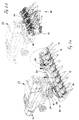
- the header 10 is shown in more detail in FIG. at the header 10 is a corn picker that on Feeder of a combine 22 is attached.
- the Middle part 12 and side parts 14, 16 each have four or two known feed and picking devices with around Vertical axis rotating feed elements on which the Pull plants through a picking gap.
- the fruit stands (Corn cobs) of the plants are fed to the combine harvester 22.
- the two force maxima set the conventional harvesting headers Sizing and working speed of the hydraulic cylinders 24 firm.
- a first spiral spring 34 is between the piston rod end of the housing 32 of the Hydraulic cylinder 24 and the piston 38 are provided and a second, also spiral spring 36 between the piston 38 and the bottom 40 of the housing 32 of the hydraulic cylinder 24.
- Die Springs 34, 36 exert forces on the piston 38 that are striving for are to bring him about his middle position, the approximately with the equilibrium shown in Figure 1b or The intermediate position of the side parts 14, 16 coincides.
- the forces exerted by the springs 34, 36 on the piston 38 are in of Figure 3 marked with line 40.
- the line 42 indicates the resulting total force curve.
- the springs 34, 36 cause the piston 38 forces to be applied are significantly lower than without Springs 34, 36. This allows the hydraulic cylinder 24 to be smaller be dimensioned and are larger swivel speeds reachable.
- the piston 38 is in position A, that of FIG. 1a corresponds, the spring 34 tensions, as in FIGS. 3 and 4 can be seen, the piston 38 in the direction of position B, which the Figure 1b corresponds to.
- the spring 36 is then ineffective.
- the spring 36 biases the piston 38 in the direction of the Position B if it is in position C.
- the spring 34 has no effect.
- the piston 38 to apply Forces are significantly reduced.
- the springs 34, 36 can be dimensioned such that they too exert forces on the piston 38 in the equilibrium position, but they balance each other out.
- One advantage is the possible steeper increase in force. It should be noted that in the Operating position and the transport position initially occurring, total forces opposing the further course of the force a different dimensioning of the springs 34, 36 and / or suitable Actuation of the hydraulic cylinder 24 can be countered.
- the springs 34, 36 could also outside of the housing 32 of the Hydraulic cylinder 24 are arranged. It would also be conceivable use only a single spring that can be subjected to tension and compression, their rest position at least approximately with the equilibrium position ( Figure 1b) coincides.
Landscapes
- Life Sciences & Earth Sciences (AREA)
- Environmental Sciences (AREA)
- Harvester Elements (AREA)
- Agricultural Machines (AREA)
- Handcart (AREA)
Abstract
Description
- Fig. 1
- schematische Ansichten eines Erntevorsatzes von hinten, der sich in Fig. 1a in der Betriebsstellung, in Fig. 1b in einer Zwischen- oder Gleichgewichtsstellung und in Figur 1c in der Transportstellung befindet,
- Fig. 2
- perspektivische Ansichten des Erntevorsatzes, der sich in Fig. 2a in der Betriebsstellung und in Fig. 2b in der Transportstellung befindet,
- Fig. 3
- die beim Verschwenken der Seitenteile entstehenden Kraftverläufe, und
- Fig. 4
- eine Ansicht eines Hydraulikzylinders zum Verschwenken eines der Seitenteile.
Claims (10)
- Verstelleinrichtung für ein bewegliches Element eines Erntevorsatzes (10), mit einem Verstellantrieb, der eingerichtet ist, das Element zwischen einer ersten Stellung und einer zweiten Stellung zu bewegen, in der es gegenüber der ersten Stellung angehoben ist, dadurch gekennzeichnet, dass das Element insbesondere durch eine Feder (34, 36) in Richtung auf die zweite Stellung hin vorspannt ist.
- Verstelleinrichtung nach Anspruch 1, dadurch gekennzeichnet, dass die erste Stellung eine Betriebsstellung und die zweite Stellung eine Transportstellung des Elements ist.
- Verstelleinrichtung nach Anspruch 1, dadurch gekennzeichnet, dass das Element von der ersten Stellung über die zweite Stellung in eine dritte Stellung bewegbar ist, wobei das Element in der zweiten Stellung gegenüber der dritten Stellung angehoben ist, und dass die Feder oder eine weitere Feder (34, 36) das Element aus der dritten Stellung in Richtung auf die zweite Stellung hin vorspannt.
- Verstelleinrichtung nach Anspruch 3, dadurch gekennzeichnet, dass die erste Stellung eine Betriebsstellung des Elements ist, dass die zweite Stellung eine Zwischenstellung des Elements ist, und dass die dritte Stellung eine Transportstellung des Elements ist.
- Verstelleinrichtung nach Anspruch 4, dadurch gekennzeichnet, dass die Zwischenstellung eine Gleichgewichtsstellung des Elements ist.
- Verstelleinrichtung nach einem der Ansprüche 1 bis 5, dadurch gekennzeichnet, dass das Element in der ersten Stellung starr mit dem Erntevorsatz (10) verbunden ist.
- Verstelleinrichtung nach einem der vorhergehenden Ansprüche, dadurch gekennzeichnet, dass das Element verschwenkbar ist.
- Verstelleinrichtung nach einem der vorhergehenden Ansprüche, dadurch gekennzeichnet, dass das Element ein schwenkbar an einem Mittelteil (12) des Erntevorsatzes (10) angelenktes Seitenteil (14, 16) ist.
- Verstelleinrichtung nach einem der vorhergehenden Ansprüche, dadurch gekennzeichnet, dass die Feder (34, 36) innerhalb eines Gehäuses (32) des Verstellantriebs angeordnet ist.
- Erntevorsatz (10) mit einer Verstelleinrichtung nach einem der vorhergehenden Ansprüche.
Applications Claiming Priority (2)
| Application Number | Priority Date | Filing Date | Title |
|---|---|---|---|
| DE10250337A DE10250337A1 (de) | 2002-10-29 | 2002-10-29 | Verstelleinrichtung für einen Erntevorsatz |
| DE10250337 | 2002-10-29 |
Publications (2)
| Publication Number | Publication Date |
|---|---|
| EP1415527A1 true EP1415527A1 (de) | 2004-05-06 |
| EP1415527B1 EP1415527B1 (de) | 2006-04-12 |
Family
ID=32087270
Family Applications (1)
| Application Number | Title | Priority Date | Filing Date |
|---|---|---|---|
| EP03103547A Expired - Lifetime EP1415527B1 (de) | 2002-10-29 | 2003-09-25 | Verstelleinrichtung für ein bewegliches Element eines Erntevorsatzes |
Country Status (7)
| Country | Link |
|---|---|
| US (1) | US20040123575A1 (de) |
| EP (1) | EP1415527B1 (de) |
| AR (1) | AR041828A1 (de) |
| AT (1) | ATE322811T1 (de) |
| BR (1) | BR0304587A (de) |
| DE (2) | DE10250337A1 (de) |
| ES (1) | ES2258699T3 (de) |
Cited By (2)
| Publication number | Priority date | Publication date | Assignee | Title |
|---|---|---|---|---|
| EP2870846A1 (de) * | 2013-11-12 | 2015-05-13 | Deere & Company | Landwirtschaftliches Arbeitsgerät |
| US20210392815A1 (en) * | 2020-06-17 | 2021-12-23 | Deere & Company | Corn head adjustment system with force relief |
Families Citing this family (22)
| Publication number | Priority date | Publication date | Assignee | Title |
|---|---|---|---|---|
| DE102005006216B4 (de) * | 2005-01-27 | 2007-06-21 | Maschinenfabrik Bernard Krone Gmbh | Selbstfahrende landwirtschaftliche Erntemaschine |
| DE102005004004A1 (de) * | 2005-01-27 | 2006-08-17 | Maschinenfabrik Bernard Krone Gmbh | Selbstfahrende landwirtschaftliche Erntemaschine |
| US8635842B2 (en) * | 2009-08-05 | 2014-01-28 | Kevin Markt | Flexible row crop header for an agricultural harvester |
| US7992372B1 (en) * | 2010-09-16 | 2011-08-09 | Deere & Company | Draper platform with breakaway joint |
| FR2977758B1 (fr) * | 2011-07-13 | 2014-06-06 | Kuhn Sa | Dispositif de ramassage articule et machine agricole equipee d'un tel dispositif |
| ITPD20120242A1 (it) * | 2012-08-06 | 2014-02-07 | Cressoni S P A Flli | Testata ripiegabile per macchina spannocchiatrice e/o mietitrebbia e metodo di ripiegatura di una testata di macchina spannocchiatrice e/o mietitrebbia |
| US9198355B2 (en) * | 2012-09-20 | 2015-12-01 | Deere & Company | Hinged row crop auger conveyor |
| ITPD20120346A1 (it) * | 2012-11-13 | 2014-05-14 | Marangon Srl | Macchina trinciatrice/falciatrice, condizionatrice, andanatrice |
| US9198349B2 (en) * | 2013-07-12 | 2015-12-01 | Deere & Company | Articulated harvesting head ground force control circuit |
| US9918430B2 (en) * | 2014-02-03 | 2018-03-20 | Cnh Industrial Canada, Ltd. | Foldable triple front disk mower for self-propelled windrowers |
| PL2992751T3 (pl) * | 2014-09-05 | 2018-01-31 | Exel Ind | Układ zbierający do zebranych plonów i odpowiednia maszyna zbierająca |
| BE1022461B1 (nl) * | 2014-09-10 | 2016-04-07 | Cnh Industrial Belgium Nv | Maaibordbalkgeheel en werkwijze voor het gebruik ervan |
| BR102016005189B1 (pt) * | 2015-03-13 | 2020-11-17 | Cnh Industrial Belgium Nv | Colheitadeira agricola |
| EP3270681B1 (de) * | 2015-03-17 | 2018-12-19 | Marangon Srl | Mähbalken für mähwerk, konditionierer, schwader mit oszilierender schnecke in drei oder mehr teilen |
| DE102015116892A1 (de) * | 2015-10-05 | 2017-04-06 | Carl Geringhoff Gmbh & Co. Kg | Schneidwerk mit verstellbarer Seitenrahmenentlastung |
| US10820509B2 (en) * | 2017-08-08 | 2020-11-03 | Cnh Industrial America Llc | Foldable corn head |
| US10433483B2 (en) * | 2017-08-21 | 2019-10-08 | Cnh Industrial America Llc | Agricultural header with one or more movable wing sections |
| US10426088B2 (en) | 2017-10-11 | 2019-10-01 | Deere & Company | Center feed assembly for a draper |
| US10537063B2 (en) * | 2017-10-11 | 2020-01-21 | Deere & Company | Folding agricultural head |
| US10433486B2 (en) | 2017-10-16 | 2019-10-08 | Deere & Company | System and method for wing float on a combine draper header |
| US10568266B2 (en) | 2017-10-17 | 2020-02-25 | Deere & Company | Self-contained combine draper wing leveler |
| US11785890B2 (en) * | 2020-06-17 | 2023-10-17 | Deere & Company | Corn head adjustment system with integrated actuation |
Citations (4)
| Publication number | Priority date | Publication date | Assignee | Title |
|---|---|---|---|---|
| US1693475A (en) * | 1921-11-07 | 1928-11-27 | Toro Mfg Company | Lawn mower |
| US2682740A (en) * | 1951-05-18 | 1954-07-06 | Toro Mfg Corp | Multirotor mower |
| US3683601A (en) * | 1969-03-05 | 1972-08-15 | Lely Nv C Van Der | Mowing mechanisms |
| US4179870A (en) * | 1977-07-13 | 1979-12-25 | Rowse Hydraulic Rakes Company, Inc. | Trailing tandem mower |
Family Cites Families (16)
| Publication number | Priority date | Publication date | Assignee | Title |
|---|---|---|---|---|
| US2970496A (en) * | 1959-02-13 | 1961-02-07 | Square D Co | Actuator |
| US3064737A (en) * | 1959-10-05 | 1962-11-20 | Continental Oil Co | Instrument anchoring device |
| US3151459A (en) * | 1963-04-10 | 1964-10-06 | Clark Equipment Co | Master cylinder |
| US3616626A (en) * | 1968-02-14 | 1971-11-02 | Hahn Inc | Mower |
| US3584777A (en) * | 1968-12-11 | 1971-06-15 | Caterpillar Tractor Co | Tailstock and feed means therefor |
| US3552398A (en) * | 1969-01-24 | 1971-01-05 | Fmc Corp | Harvester with torque responsive snapping rolls |
| GB1543324A (en) * | 1975-05-02 | 1979-04-04 | Clayson Nv | Resilient mounting of attachment for agricultural machinery |
| DE2728199A1 (de) * | 1977-06-23 | 1979-01-04 | Schumacher | Vorrichtung zum schwenken einer maschinenbaugruppe |
| US4336846A (en) * | 1981-03-05 | 1982-06-29 | International Harvester Co. | Agricultural folding tool bar |
| US4409780A (en) * | 1982-03-11 | 1983-10-18 | Kansas State University Research Foundation | Folding header assembly |
| US4546601A (en) * | 1983-02-11 | 1985-10-15 | Skovhoj Jens B | Lawn and garden maintenance apparatus |
| IT1256795B (it) * | 1992-01-31 | 1995-12-15 | Capello R & F Flli | Testata ripiegabile per la raccolata del mais, perfezionata. |
| FR2729817B1 (fr) * | 1995-01-27 | 1997-04-11 | Kuhn Sa | Machine de coupe avec dispositif de commande de l'action d'un ressort d'allegement du mecanisme de coupe |
| US5673543A (en) * | 1996-01-04 | 1997-10-07 | Byron Enterprises, Inc | Foldable corn head with unobstructed auger |
| DE29817666U1 (de) * | 1998-10-05 | 1998-12-10 | Maschinenfabrik Kemper GmbH & Co. KG, 48703 Stadtlohn | Maschine zum Mähen von Mais u.dgl. stengelartigem Erntegut |
| US6220008B1 (en) * | 1999-04-02 | 2001-04-24 | Dan D. Rowse | Wheel rake spring assembly |
-
2002
- 2002-10-29 DE DE10250337A patent/DE10250337A1/de not_active Withdrawn
-
2003
- 2003-09-25 ES ES03103547T patent/ES2258699T3/es not_active Expired - Lifetime
- 2003-09-25 DE DE50302945T patent/DE50302945D1/de not_active Expired - Fee Related
- 2003-09-25 EP EP03103547A patent/EP1415527B1/de not_active Expired - Lifetime
- 2003-09-25 AT AT03103547T patent/ATE322811T1/de not_active IP Right Cessation
- 2003-10-17 US US10/688,044 patent/US20040123575A1/en not_active Abandoned
- 2003-10-24 AR ARP030103899A patent/AR041828A1/es active IP Right Grant
- 2003-10-24 BR BR0304587-0A patent/BR0304587A/pt not_active IP Right Cessation
Patent Citations (4)
| Publication number | Priority date | Publication date | Assignee | Title |
|---|---|---|---|---|
| US1693475A (en) * | 1921-11-07 | 1928-11-27 | Toro Mfg Company | Lawn mower |
| US2682740A (en) * | 1951-05-18 | 1954-07-06 | Toro Mfg Corp | Multirotor mower |
| US3683601A (en) * | 1969-03-05 | 1972-08-15 | Lely Nv C Van Der | Mowing mechanisms |
| US4179870A (en) * | 1977-07-13 | 1979-12-25 | Rowse Hydraulic Rakes Company, Inc. | Trailing tandem mower |
Cited By (3)
| Publication number | Priority date | Publication date | Assignee | Title |
|---|---|---|---|---|
| EP2870846A1 (de) * | 2013-11-12 | 2015-05-13 | Deere & Company | Landwirtschaftliches Arbeitsgerät |
| US20210392815A1 (en) * | 2020-06-17 | 2021-12-23 | Deere & Company | Corn head adjustment system with force relief |
| US12114602B2 (en) * | 2020-06-17 | 2024-10-15 | Deere & Company | Corn head adjustment system with force relief |
Also Published As
| Publication number | Publication date |
|---|---|
| US20040123575A1 (en) | 2004-07-01 |
| AR041828A1 (es) | 2005-06-01 |
| BR0304587A (pt) | 2004-08-31 |
| ES2258699T3 (es) | 2006-09-01 |
| EP1415527B1 (de) | 2006-04-12 |
| ATE322811T1 (de) | 2006-04-15 |
| DE50302945D1 (de) | 2006-05-24 |
| DE10250337A1 (de) | 2004-05-19 |
Similar Documents
| Publication | Publication Date | Title |
|---|---|---|
| EP1415527A1 (de) | Verstelleinrichtung für ein bewegliches Element eines Erntevorsatzes | |
| DE2428917C3 (de) | Bodenbearbeitungsgerät | |
| DE69705807T2 (de) | Heuwerbungsmaschine | |
| DE602004009338T2 (de) | Landmaschine zum schwaden von auf dem boden liegenden produkten | |
| DE2804129A1 (de) | Portalschlepper | |
| EP1287732A1 (de) | Erntevorsatz | |
| EP1095555B1 (de) | Heuwerbungsmaschine | |
| EP1131992A1 (de) | Mähmaschine | |
| DE102008042392B4 (de) | Erntevorsatz für landwirtschaftliche Erntemaschinen | |
| EP1142467B1 (de) | Vorrichtung zum Pflücken der Fruchtstände stängeliger Erntegüter | |
| DE905434C (de) | Mehrfach-Scheibenegge fuer einen Schlepper | |
| DE2632002C2 (de) | Mähmaschine | |
| DE102015100273A1 (de) | Landwirtschaftliches Arbeitsgerät mit Zusatzfahrwerk | |
| AT13227U1 (de) | Gezogene landwirtschaftliche Maschine | |
| DE102012102084B4 (de) | Verlade- und Transportvorrichtung für landwirtschaftliche Schneidwerke | |
| DE102011111251B4 (de) | Landmaschine | |
| DE2058255A1 (de) | Mit Abweisern am Schneidwerktisch versehener Maehdrescher | |
| DE69602592T2 (de) | Langer anhänge pflug mit gegliedertem grindel | |
| DE3106660C2 (de) | Bodenbearbeitungsgerät im wesentlichen in Art einer Scheibenegge oder dergleichen | |
| EP3005853B1 (de) | Landwirtschaftliches arbeitsgerät und verfahren zum betreiben eines landwirtschaftlichen arbeitsgeräts | |
| DE202017107372U1 (de) | Landwirtschaftliche Ernte- und/oder Bodenbearbeitungsmaschine | |
| DE1058294B (de) | Schlepperanbaupflug, insbesondere Anbaubeetpflug, der zum Normal- und Grenzpfluegen verwendbar ist | |
| EP0082207B1 (de) | Drehpflug mit einer Rahmenschwenkeinrichtung | |
| EP0145027A2 (de) | Von einem Ackerschlepper nachgeschleppter Pflug | |
| DE102015206142A1 (de) | Erntevorsatz für landwirtschaftliche Erntemaschinen |
Legal Events
| Date | Code | Title | Description |
|---|---|---|---|
| PUAI | Public reference made under article 153(3) epc to a published international application that has entered the european phase |
Free format text: ORIGINAL CODE: 0009012 |
|
| AK | Designated contracting states |
Kind code of ref document: A1 Designated state(s): AT BE BG CH CY CZ DE DK EE ES FI FR GB GR HU IE IT LI LU MC NL PT RO SE SI SK TR |
|
| AX | Request for extension of the european patent |
Extension state: AL LT LV MK |
|
| 17P | Request for examination filed |
Effective date: 20041108 |
|
| AKX | Designation fees paid |
Designated state(s): AT BE BG CH CY CZ DE DK EE ES FI FR GB GR HU IE IT LI LU MC NL PT RO SE SI SK TR |
|
| 17Q | First examination report despatched |
Effective date: 20050210 |
|
| GRAP | Despatch of communication of intention to grant a patent |
Free format text: ORIGINAL CODE: EPIDOSNIGR1 |
|
| GRAS | Grant fee paid |
Free format text: ORIGINAL CODE: EPIDOSNIGR3 |
|
| GRAA | (expected) grant |
Free format text: ORIGINAL CODE: 0009210 |
|
| AK | Designated contracting states |
Kind code of ref document: B1 Designated state(s): AT BE BG CH CY CZ DE DK EE ES FI FR GB GR HU IE IT LI LU MC NL PT RO SE SI SK TR |
|
| PG25 | Lapsed in a contracting state [announced via postgrant information from national office to epo] |
Ref country code: RO Free format text: LAPSE BECAUSE OF FAILURE TO SUBMIT A TRANSLATION OF THE DESCRIPTION OR TO PAY THE FEE WITHIN THE PRESCRIBED TIME-LIMIT Effective date: 20060412 Ref country code: IE Free format text: LAPSE BECAUSE OF FAILURE TO SUBMIT A TRANSLATION OF THE DESCRIPTION OR TO PAY THE FEE WITHIN THE PRESCRIBED TIME-LIMIT Effective date: 20060412 Ref country code: FI Free format text: LAPSE BECAUSE OF FAILURE TO SUBMIT A TRANSLATION OF THE DESCRIPTION OR TO PAY THE FEE WITHIN THE PRESCRIBED TIME-LIMIT Effective date: 20060412 Ref country code: NL Free format text: LAPSE BECAUSE OF FAILURE TO SUBMIT A TRANSLATION OF THE DESCRIPTION OR TO PAY THE FEE WITHIN THE PRESCRIBED TIME-LIMIT Effective date: 20060412 Ref country code: SK Free format text: LAPSE BECAUSE OF FAILURE TO SUBMIT A TRANSLATION OF THE DESCRIPTION OR TO PAY THE FEE WITHIN THE PRESCRIBED TIME-LIMIT Effective date: 20060412 Ref country code: SI Free format text: LAPSE BECAUSE OF FAILURE TO SUBMIT A TRANSLATION OF THE DESCRIPTION OR TO PAY THE FEE WITHIN THE PRESCRIBED TIME-LIMIT Effective date: 20060412 Ref country code: GB Free format text: LAPSE BECAUSE OF FAILURE TO SUBMIT A TRANSLATION OF THE DESCRIPTION OR TO PAY THE FEE WITHIN THE PRESCRIBED TIME-LIMIT Effective date: 20060412 Ref country code: CZ Free format text: LAPSE BECAUSE OF FAILURE TO SUBMIT A TRANSLATION OF THE DESCRIPTION OR TO PAY THE FEE WITHIN THE PRESCRIBED TIME-LIMIT Effective date: 20060412 |
|
| REG | Reference to a national code |
Ref country code: GB Ref legal event code: FG4D Free format text: NOT ENGLISH |
|
| REG | Reference to a national code |
Ref country code: CH Ref legal event code: EP |
|
| REF | Corresponds to: |
Ref document number: 50302945 Country of ref document: DE Date of ref document: 20060524 Kind code of ref document: P |
|
| REG | Reference to a national code |
Ref country code: IE Ref legal event code: FG4D Free format text: LANGUAGE OF EP DOCUMENT: GERMAN |
|
| PG25 | Lapsed in a contracting state [announced via postgrant information from national office to epo] |
Ref country code: DK Free format text: LAPSE BECAUSE OF FAILURE TO SUBMIT A TRANSLATION OF THE DESCRIPTION OR TO PAY THE FEE WITHIN THE PRESCRIBED TIME-LIMIT Effective date: 20060712 Ref country code: SE Free format text: LAPSE BECAUSE OF FAILURE TO SUBMIT A TRANSLATION OF THE DESCRIPTION OR TO PAY THE FEE WITHIN THE PRESCRIBED TIME-LIMIT Effective date: 20060712 |
|
| REG | Reference to a national code |
Ref country code: ES Ref legal event code: FG2A Ref document number: 2258699 Country of ref document: ES Kind code of ref document: T3 |
|
| PG25 | Lapsed in a contracting state [announced via postgrant information from national office to epo] |
Ref country code: PT Free format text: LAPSE BECAUSE OF FAILURE TO SUBMIT A TRANSLATION OF THE DESCRIPTION OR TO PAY THE FEE WITHIN THE PRESCRIBED TIME-LIMIT Effective date: 20060912 |
|
| PG25 | Lapsed in a contracting state [announced via postgrant information from national office to epo] |
Ref country code: BE Free format text: LAPSE BECAUSE OF NON-PAYMENT OF DUE FEES Effective date: 20060930 Ref country code: MC Free format text: LAPSE BECAUSE OF NON-PAYMENT OF DUE FEES Effective date: 20060930 |
|
| NLV1 | Nl: lapsed or annulled due to failure to fulfill the requirements of art. 29p and 29m of the patents act | ||
| GBV | Gb: ep patent (uk) treated as always having been void in accordance with gb section 77(7)/1977 [no translation filed] |
Effective date: 20060412 |
|
| ET | Fr: translation filed | ||
| REG | Reference to a national code |
Ref country code: IE Ref legal event code: FD4D |
|
| PLBE | No opposition filed within time limit |
Free format text: ORIGINAL CODE: 0009261 |
|
| STAA | Information on the status of an ep patent application or granted ep patent |
Free format text: STATUS: NO OPPOSITION FILED WITHIN TIME LIMIT |
|
| 26N | No opposition filed |
Effective date: 20070115 |
|
| PG25 | Lapsed in a contracting state [announced via postgrant information from national office to epo] |
Ref country code: AT Free format text: LAPSE BECAUSE OF NON-PAYMENT OF DUE FEES Effective date: 20060925 |
|
| BERE | Be: lapsed |
Owner name: MASCHINENFABRIK KEMPER G.M.B.H. & CO. KG Effective date: 20060930 |
|
| PG25 | Lapsed in a contracting state [announced via postgrant information from national office to epo] |
Ref country code: GR Free format text: LAPSE BECAUSE OF FAILURE TO SUBMIT A TRANSLATION OF THE DESCRIPTION OR TO PAY THE FEE WITHIN THE PRESCRIBED TIME-LIMIT Effective date: 20060713 |
|
| REG | Reference to a national code |
Ref country code: CH Ref legal event code: PL |
|
| PG25 | Lapsed in a contracting state [announced via postgrant information from national office to epo] |
Ref country code: BG Free format text: LAPSE BECAUSE OF FAILURE TO SUBMIT A TRANSLATION OF THE DESCRIPTION OR TO PAY THE FEE WITHIN THE PRESCRIBED TIME-LIMIT Effective date: 20060712 Ref country code: EE Free format text: LAPSE BECAUSE OF FAILURE TO SUBMIT A TRANSLATION OF THE DESCRIPTION OR TO PAY THE FEE WITHIN THE PRESCRIBED TIME-LIMIT Effective date: 20060412 |
|
| PG25 | Lapsed in a contracting state [announced via postgrant information from national office to epo] |
Ref country code: TR Free format text: LAPSE BECAUSE OF FAILURE TO SUBMIT A TRANSLATION OF THE DESCRIPTION OR TO PAY THE FEE WITHIN THE PRESCRIBED TIME-LIMIT Effective date: 20060412 Ref country code: LU Free format text: LAPSE BECAUSE OF NON-PAYMENT OF DUE FEES Effective date: 20060925 Ref country code: LI Free format text: LAPSE BECAUSE OF NON-PAYMENT OF DUE FEES Effective date: 20070930 Ref country code: HU Free format text: LAPSE BECAUSE OF FAILURE TO SUBMIT A TRANSLATION OF THE DESCRIPTION OR TO PAY THE FEE WITHIN THE PRESCRIBED TIME-LIMIT Effective date: 20061013 Ref country code: CH Free format text: LAPSE BECAUSE OF NON-PAYMENT OF DUE FEES Effective date: 20070930 |
|
| PGFP | Annual fee paid to national office [announced via postgrant information from national office to epo] |
Ref country code: ES Payment date: 20080926 Year of fee payment: 6 |
|
| PG25 | Lapsed in a contracting state [announced via postgrant information from national office to epo] |
Ref country code: CY Free format text: LAPSE BECAUSE OF FAILURE TO SUBMIT A TRANSLATION OF THE DESCRIPTION OR TO PAY THE FEE WITHIN THE PRESCRIBED TIME-LIMIT Effective date: 20060412 |
|
| PGFP | Annual fee paid to national office [announced via postgrant information from national office to epo] |
Ref country code: FR Payment date: 20080917 Year of fee payment: 6 Ref country code: IT Payment date: 20080925 Year of fee payment: 6 |
|
| PGFP | Annual fee paid to national office [announced via postgrant information from national office to epo] |
Ref country code: DE Payment date: 20080820 Year of fee payment: 6 |
|
| REG | Reference to a national code |
Ref country code: FR Ref legal event code: ST Effective date: 20100531 |
|
| PG25 | Lapsed in a contracting state [announced via postgrant information from national office to epo] |
Ref country code: DE Free format text: LAPSE BECAUSE OF NON-PAYMENT OF DUE FEES Effective date: 20100401 Ref country code: FR Free format text: LAPSE BECAUSE OF NON-PAYMENT OF DUE FEES Effective date: 20090930 |
|
| PG25 | Lapsed in a contracting state [announced via postgrant information from national office to epo] |
Ref country code: IT Free format text: LAPSE BECAUSE OF NON-PAYMENT OF DUE FEES Effective date: 20090925 |
|
| REG | Reference to a national code |
Ref country code: ES Ref legal event code: FD2A Effective date: 20110711 |
|
| PG25 | Lapsed in a contracting state [announced via postgrant information from national office to epo] |
Ref country code: ES Free format text: LAPSE BECAUSE OF NON-PAYMENT OF DUE FEES Effective date: 20110629 |
|
| PG25 | Lapsed in a contracting state [announced via postgrant information from national office to epo] |
Ref country code: ES Free format text: LAPSE BECAUSE OF NON-PAYMENT OF DUE FEES Effective date: 20090926 |