EP1415758A1 - Bearbeitungseinheit für eine programmgesteuerte Fräs- und Bohrmaschine - Google Patents
Bearbeitungseinheit für eine programmgesteuerte Fräs- und Bohrmaschine Download PDFInfo
- Publication number
- EP1415758A1 EP1415758A1 EP03025034A EP03025034A EP1415758A1 EP 1415758 A1 EP1415758 A1 EP 1415758A1 EP 03025034 A EP03025034 A EP 03025034A EP 03025034 A EP03025034 A EP 03025034A EP 1415758 A1 EP1415758 A1 EP 1415758A1
- Authority
- EP
- European Patent Office
- Prior art keywords
- head
- spindle
- processing unit
- axis
- unit according
- Prior art date
- Legal status (The legal status is an assumption and is not a legal conclusion. Google has not performed a legal analysis and makes no representation as to the accuracy of the status listed.)
- Granted
Links
- 238000003801 milling Methods 0.000 title claims description 8
- 238000005553 drilling Methods 0.000 claims description 3
- 238000005096 rolling process Methods 0.000 claims description 3
- 238000003754 machining Methods 0.000 description 5
- 230000005540 biological transmission Effects 0.000 description 3
- 210000001520 comb Anatomy 0.000 description 2
- 239000007787 solid Substances 0.000 description 2
- 239000000969 carrier Substances 0.000 description 1
- 238000001816 cooling Methods 0.000 description 1
- 238000006073 displacement reaction Methods 0.000 description 1
- 238000005516 engineering process Methods 0.000 description 1
- 239000012530 fluid Substances 0.000 description 1
- 238000011010 flushing procedure Methods 0.000 description 1
Images


Classifications
-
- B—PERFORMING OPERATIONS; TRANSPORTING
- B23—MACHINE TOOLS; METAL-WORKING NOT OTHERWISE PROVIDED FOR
- B23Q—DETAILS, COMPONENTS, OR ACCESSORIES FOR MACHINE TOOLS, e.g. ARRANGEMENTS FOR COPYING OR CONTROLLING; MACHINE TOOLS IN GENERAL CHARACTERISED BY THE CONSTRUCTION OF PARTICULAR DETAILS OR COMPONENTS; COMBINATIONS OR ASSOCIATIONS OF METAL-WORKING MACHINES, NOT DIRECTED TO A PARTICULAR RESULT
- B23Q1/00—Members which are comprised in the general build-up of a form of machine, particularly relatively large fixed members
- B23Q1/0009—Energy-transferring means or control lines for movable machine parts; Control panels or boxes; Control parts
- B23Q1/0018—Energy-transferring means or control lines for movable machine parts; Control panels or boxes; Control parts comprising hydraulic means
- B23Q1/0027—Energy-transferring means or control lines for movable machine parts; Control panels or boxes; Control parts comprising hydraulic means between moving parts between which an uninterrupted energy-transfer connection is maintained
- B23Q1/0036—Energy-transferring means or control lines for movable machine parts; Control panels or boxes; Control parts comprising hydraulic means between moving parts between which an uninterrupted energy-transfer connection is maintained one of those parts being a tool
-
- B—PERFORMING OPERATIONS; TRANSPORTING
- B23—MACHINE TOOLS; METAL-WORKING NOT OTHERWISE PROVIDED FOR
- B23Q—DETAILS, COMPONENTS, OR ACCESSORIES FOR MACHINE TOOLS, e.g. ARRANGEMENTS FOR COPYING OR CONTROLLING; MACHINE TOOLS IN GENERAL CHARACTERISED BY THE CONSTRUCTION OF PARTICULAR DETAILS OR COMPONENTS; COMBINATIONS OR ASSOCIATIONS OF METAL-WORKING MACHINES, NOT DIRECTED TO A PARTICULAR RESULT
- B23Q1/00—Members which are comprised in the general build-up of a form of machine, particularly relatively large fixed members
- B23Q1/25—Movable or adjustable work or tool supports
- B23Q1/44—Movable or adjustable work or tool supports using particular mechanisms
- B23Q1/50—Movable or adjustable work or tool supports using particular mechanisms with rotating pairs only, the rotating pairs being the first two elements of the mechanism
- B23Q1/54—Movable or adjustable work or tool supports using particular mechanisms with rotating pairs only, the rotating pairs being the first two elements of the mechanism two rotating pairs only
-
- Y—GENERAL TAGGING OF NEW TECHNOLOGICAL DEVELOPMENTS; GENERAL TAGGING OF CROSS-SECTIONAL TECHNOLOGIES SPANNING OVER SEVERAL SECTIONS OF THE IPC; TECHNICAL SUBJECTS COVERED BY FORMER USPC CROSS-REFERENCE ART COLLECTIONS [XRACs] AND DIGESTS
- Y10—TECHNICAL SUBJECTS COVERED BY FORMER USPC
- Y10T—TECHNICAL SUBJECTS COVERED BY FORMER US CLASSIFICATION
- Y10T29/00—Metal working
- Y10T29/51—Plural diverse manufacturing apparatus including means for metal shaping or assembling
- Y10T29/5104—Type of machine
- Y10T29/5105—Drill press
- Y10T29/5107—Drilling and other
-
- Y—GENERAL TAGGING OF NEW TECHNOLOGICAL DEVELOPMENTS; GENERAL TAGGING OF CROSS-SECTIONAL TECHNOLOGIES SPANNING OVER SEVERAL SECTIONS OF THE IPC; TECHNICAL SUBJECTS COVERED BY FORMER USPC CROSS-REFERENCE ART COLLECTIONS [XRACs] AND DIGESTS
- Y10—TECHNICAL SUBJECTS COVERED BY FORMER USPC
- Y10T—TECHNICAL SUBJECTS COVERED BY FORMER US CLASSIFICATION
- Y10T408/00—Cutting by use of rotating axially moving tool
- Y10T408/91—Machine frame
- Y10T408/93—Machine frame including pivotally mounted tool-carrier
-
- Y—GENERAL TAGGING OF NEW TECHNOLOGICAL DEVELOPMENTS; GENERAL TAGGING OF CROSS-SECTIONAL TECHNOLOGIES SPANNING OVER SEVERAL SECTIONS OF THE IPC; TECHNICAL SUBJECTS COVERED BY FORMER USPC CROSS-REFERENCE ART COLLECTIONS [XRACs] AND DIGESTS
- Y10—TECHNICAL SUBJECTS COVERED BY FORMER USPC
- Y10T—TECHNICAL SUBJECTS COVERED BY FORMER US CLASSIFICATION
- Y10T409/00—Gear cutting, milling, or planing
- Y10T409/30—Milling
- Y10T409/306664—Milling including means to infeed rotary cutter toward work
- Y10T409/307672—Angularly adjustable cutter head
-
- Y—GENERAL TAGGING OF NEW TECHNOLOGICAL DEVELOPMENTS; GENERAL TAGGING OF CROSS-SECTIONAL TECHNOLOGIES SPANNING OVER SEVERAL SECTIONS OF THE IPC; TECHNICAL SUBJECTS COVERED BY FORMER USPC CROSS-REFERENCE ART COLLECTIONS [XRACs] AND DIGESTS
- Y10—TECHNICAL SUBJECTS COVERED BY FORMER USPC
- Y10T—TECHNICAL SUBJECTS COVERED BY FORMER US CLASSIFICATION
- Y10T409/00—Gear cutting, milling, or planing
- Y10T409/30—Milling
- Y10T409/30784—Milling including means to adustably position cutter
- Y10T409/308512—Compound angular adjustment
Definitions
- the invention relates to a processing unit for a program-controlled Milling and drilling machine with one in several coordinate axes movable head carrier, the one 45 ° forward-down contains pointing axis of rotation, one on the face of the head carrier the 45 ° axis of rotation rotatably arranged swivel head, a Swivel head, fixed spindle head with one work spindle, whose axis runs at an angle of 45 ° to the 45 ° axis of rotation.
- DE 44 02 084 A is a generic processing unit described that a movable on a machine stand Carrying housing, on the 45 ° inclined to the vertical, a swivel milling head facing downwards with one also inclined at 45 ° to the vertical Contact surface can be rotated about an axis perpendicular to the front wall is led.
- a swivel milling head there is one at 45 ° to the axis of rotation arranged work spindle mounted by appropriate rotation of the swivel milling head between a horizontal and a vertical processing position can be pivoted.
- Support housing for the swivel head is a controllable drive motor arranged, the shaft coaxial to the axis of rotation, the work spindle via a pair of bevel gears and a sliding gear set, optionally with two drives different speeds.
- the shaft of the spindle motor is formed as a hollow shaft and surrounds the motor housing with play and also solid shaft protruding through the swivel head for turning of the swivel head, at the inner end of a worm gear and the outer lower end of the housing of the swivel head are attached.
- An end toothing is formed at the end of the swivel head and is located in an annular recess of the head carrier a matching spur gear.
- the swivel head is prescribed in both spur gears Angular position fixed positively.
- the central solid shaft axially displaceable and over an end plate with a elastically preloaded pressure medium cylinder connected.
- the object of the invention is to provide a processing unit for a milling and Drilling machine to create that with simplified constructive Structure and increased rigidity more universal operations, for example Machining during the swiveling movements of the Milling head, enables.
- the Swivel head a hollow cylindrical one coaxial to the 45 ° axis of rotation Has housing part in which the spindle motor is fixed, and that the head carrier has a hollow cylindrical housing attachment, in which the housing part of the swivel head is rotatably mounted.
- the rotary drive of the swivel head can be rotated to the 45 ° axis coaxial electrical direct drive or a conventional electric motor be used, which over a play-free by tensioning Toothed belt drive and a spur gear with one on the motor housing attached toothed ring is kinematically connected.
- a drive train guarantees the play-free transmission of high torques as well as a highly precise positioning of the swivel head in predetermined Angular positions.
- the swivel head is stored in the housing of the head carrier expediently by means of a fastened in the hollow cylindrical housing approach Support ring, which in a on the hollow cylindrical housing part of the Swing head trained circumferential groove engages and therein by means three rolling bearings is mounted.
- a special feature consists in the provision of an outer flexible tube for protected inclusion of energy and media lines by the Head carrier leads to the housing of the work spindle.
- This flexible pipe is expedient via a rotatable elbow to the head carrier and pivotable to the via an adapter Spindle housing connected.
- the pivotability of the pipe connection can be attached to the spindle housing through special training of the adapter can be achieved with a socket crowned outer surfaces, on which a pivotable end ring in the Sliding fit.
- To prevent the lines from buckling can prevent rolling elements in the adapter, especially Rollers, freely rotatable, on which the different Create lines.
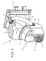
- the processing unit has an angled one Head carrier 1, which has a vertical rear plate or frame-like support structure 2, a voluminous middle part 3 and one tilted forward-down at an angle of 45 ° has hollow cylindrical housing extension 4.
- a Swivel head 5 about the central axis 27 of the hollow cylindrical housing attachment 4 rotatably mounted, on one side a spindle head 6 at a 45 ° angle to the central axis 27 of the housing attachment 4 is rigidly attached.
- Transversely in this spindle head 6 is a work spindle 7 stored.
- a flexible tube 9 can be pivoted by means of an adapter 10 connected, the upper end of a rotatable elbow 11 is connected to the middle part 3 of the head carrier 1.
- FIG. 2 shows the internal functional parts of the processing unit according to the invention shown in a schematic vertical section.
- an adjusting motor 15 is arranged, the output shaft of which Timing belt 16 drives to maintain constant tension It is part of a so-called cyclo-transmission and slightly different from each other angularly offset gears 17 runs, of which in Fig. 2nd only one is visible.
- Each gear 17 drives one in the head carrier 1 mounted shaft 18 and a pinion 19 attached to it comb with a spur-toothed ring 20.
- This gear ring 20 is on the housing 21 of a spindle motor designed as a hollow cylinder 22 attached.
- the stator 23 of this spindle motor 22 is via a provided with cooling channels sleeve 24 fixed to the motor housing 21 connected.
- the rotor 25 of the spindle motor 22 is firmly seated on one Hollow shaft 26, the longitudinal axis 27 at an angle of 45 ° to Vertical sloping downward.
- a bevel gear 28 which has a bevel gear 29 combs, which part one on a in the housing 30 of Swivel head freely rotatably mounted shaft 31 fixed tooth sleeve 32 is.
- This toothed sleeve 32 meshes with the larger part 33 Slider wheel, which is fixed on a countershaft 34 and with an end toothing 35 on the outer circumference of a work spindle 36 combs. Sits on a front section of this work spindle 36 a larger gear 37, which is caused by a displacement of the sliding wheel 33 on the countershaft 34 with its smaller spur gear 38 in Intervention.
- the housing 30 of the swivel head 5 has one to the axis of rotation 27 coaxial housing part 40, which in the hollow cylindrical housing approach 4 of the head carrier 1 engages.
- On the inner wall of this Housing attachment 4 is a stable and rigid support ring 41 attached, the in a circumferential groove formed in the housing projection 40 is guided by three roller bearings 42, which for receiving radial and axial loads are designed.
- FIG. 2 shown position after clamping a tool in the work spindle the spindle motor fixed in the housing of the swivel head 5 turned on, the motor shaft 26, the work spindle 7th drives via the bevel gear 28, 29 and the manual transmission 33, 35.
- the spindle head 6 For pivoting the spindle head 6 into an inclined position or the servomotor 15 is switched on in its vertical position, of the pre-tensioned toothed belt drive 16, 17 and the spur gear pair 19, 20, the motor housing 21 rotated about the 45 ° axis of rotation 25.
- the flex tube 9 shown in FIGS. 1, 3 and 4 is a known one Component that is characterized by a relatively high compressive strength and a is characterized by sufficient flexibility.
- the elbow 11 is by means of a conventional Pipe clamp attached.
- a rotating ring 50, a spring ring 51 and an end ring 52 mounted so that the elbow 11 around the central axis of this Rings 50, 51, 52 can be rotated.
- FIG illustrated adapter 53 At the other end of the flexible tube 9 is an axial section in FIG illustrated adapter 53 by means of a conventional pipe clamp attached.
- This adapter contains an approximately square cross section Ring body 54 in which a likewise square insert 55 is attached by means of screws, the upper and lower surfaces 56, 57 are spherical or circular arc-shaped.
- the upper part 58 and the lower part 59 are also one square end member 60 guided in the sliding fit, in which two lateral rollers 61, 62 are mounted.
- This end member 60 is - as from 1 can be seen - on the box-shaped rear part 8 of the spindle head 6 attached.
- the length of the flex tube 9 and the positions of the two Connections 10, 11 are selected so that when the Spindle head 6 about the 45 ° axis of rotation 27, the flex tube 9 its bend maintains approximately and only in the angle head 11 a twist and a pivoting takes place in the adapter 10.
- the invention is not based on those described and illustrated above Embodiments limited.
- the manual transmission 33 to 38 are omitted and the spur gear 32 with a corresponding increase in diameter directly with the toothing 35 are brought into engagement on the spindle body 36. hereby the processing unit is naturally downsized.
- toothed belt 16 and braced gear train 17, 18, 19 for the Swivel head 5 can also use an electrical direct drive are, the hollow cylindrical stator inside the head carrier 1 and its rotor in the housing part 40 and / or on the housing 21 of the spindle motor 22 are attached.
- the Swivel head 5 in the head carrier 6 can instead of the support ring shown 41 with the roller bearings 42 also another suitable bearing arrangement are used that are high in the axial and radial directions is resilient and precise smooth turning movements of the Allows swivel head around the 45 ° axis of rotation 27.
- Around the swivel head even with extremely high loads in preselected positions or Fixing positions can be an additional hydraulic and / or mechanically operated clamping device with at least one disc or sleeve-shaped clamping element (e.g. according to DE 195 22 711 C2 or DE 41 22 711 A1) between a suitable one Component of the head carrier and the swivel head may be provided.
- the flexible tube with the rotatable elbow and the pivoting movement Adapters also used in other processing units a swivel head that can be turned around a 45 ° axis of rotation with a fixed work spindle.
Landscapes
- Engineering & Computer Science (AREA)
- Mechanical Engineering (AREA)
- Machine Tool Units (AREA)
- Gear Transmission (AREA)
- General Details Of Gearings (AREA)
- Drilling And Boring (AREA)
- Milling Processes (AREA)
- Turning (AREA)
Abstract
Description
- Fig. 1
- eine Bearbeitungseinheit in perspektivischer Vorderansicht;
- Fig. 2
- eine Bearbeitungseinheit im schematischen Vertikalschnitt;
- Fig. 3
- das bei der Bearbeitungseinheit nach Fig. 1 verwendete Flexrohr mit beidseitigen Anschlüssen in perspektivischer Explosionsdarstellung;
- Fig. 4
- einen verschwenkbaren Endanschluss des Flexrohres mit dem Adapter.
Claims (9)
- Bearbeitungseinheit für eine programmgesteuerte Fräs- und Bohrmaschine mitdadurch gekennzeichnet, dasseinem in mehreren Koordinatenachsen verfahrbaren Kopfträger (1), der eine um 45° nach vorne-unten weisende Drehachse (27) enthält,einem stirnseitig am Kopfträger (1) um die 45°-Drehachse (27) motorisch verdrehbar angeordneten Schwenkkopf (5),einem am Schwenkkopf (5) fest montierten Spindelkopf (6) mit einer Arbeitsspindel (7), deren Achse unter einem Winkel von 45° zur 45°-Drehachse (27) verläuft,einem koaxial zur 45°-Drehachse (27) ausgerichteten Spindelmotor (22) undeinem im Schwenkkopf (5) angeordneten Winkelgetriebe (28, 29) für den Spindelantrieb,der Schwenkkopf (5) einen zur 45°-Drehachse (27) koaxialen hohlzylindrischen Gehäuseteil (40) aufweist, in dem der Spindelmotor (22) befestigt ist, undder Kopfträger (1) einen Gehäuseansatz (4) aufweist, in welchem der Gehäuseteil (40) des Schwenkkopfes (5) drehbar gelagert ist.
- Bearbeitungseinheit nach Anspruch 1,
dadurch gekennzeichnet, dass
der Drehantrieb (15) zum Verdrehen des Schwenkkopfes (5) im Kopfträger (1) einen spielfrei verspannten Getriebezug mit einem Zahnriementrieb (16, 17) und einem Stirnrad (19) aufweist, das mit einem auf dem Motorgehäuse (21) befestigten Zahnring (20) ständig in Eingriff steht. - Bearbeitungseinheit nach Anspruch 1 oder 2,
dadurch gekennzeichnet, dass
dem Winkelgetriebe (28, 29) ein Mehrstufengetriebe (32, 33, 35, 37, 38) nachgeschaltet ist. - Bearbeitungseinheit nach einem der vorstehenden Ansprüche,
dadurch gekennzeichnet, dass
im hohlzylindrischen Gehäuseansatz (4) des Kopfträgers (1) mindestens ein Tragring (41) befestigt ist, der in mindestens einer am hohlzylindrischen Gehäuseteil (40) des Schwenkkopfes (5) ausgebildeten Umfangsnut gelagert ist. - Bearbeitungseinheit nach einem der vorstehenden Ansprüche,
dadurch gekennzeichnet, dass
das Gehäuse (21) des Spindelmotors (22) mit seinem vorderen etwa hälftigen Teil im Gehäuseteil (40) des Schwenkkopfes (5) befestigt ist und mit seinem hinteren den Zahnring (20) tragenden Teil in den Kopfträger (1) hineinragt. - Bearbeitungseinheit nach dem Oberbegriff des Anspruchs 1,
dadurch gekennzeichnet, dass
ein äußeres Flexrohr (9) zur geschützten Aufnahme der Energieund Medienleitungen vom Kopfträger (1) zum Gehäuse des Spindelkopfes (6) führt. - Bearbeitungseinheit nach Anspruch 6,
dadurch gekennzeichnet, dass
das Flexrohr (9) über einen verdrehbaren Winkelstutzen (11) an den Kopfträger (1) und über einen Adapter (10) verschwenkbar an das Gehäuse des Spindelkopfes (6) angeschlossen ist. - Bearbeitungseinheit nach Anspruch 7,
dadurch gekennzeichnet, dass
der Adapter (11) eine Buchse (55) mit balligen Außenflächen (56, 57) enthält, an denen ein schwenkbarer Endring (60) im Gleitsitz anliegt. - Bearbeitungseinheit nach Anspruch 7 oder 8,
dadurch gekennzeichnet, dass
im Adapter (53) Wälzkörper (61, 62) gelagert sind.
Applications Claiming Priority (2)
| Application Number | Priority Date | Filing Date | Title |
|---|---|---|---|
| DE10251257A DE10251257B4 (de) | 2002-11-04 | 2002-11-04 | Bearbeitungseinheit für eine programmgesteuerte Fräs- und Bohrmaschine |
| DE10251257 | 2002-11-04 |
Publications (2)
| Publication Number | Publication Date |
|---|---|
| EP1415758A1 true EP1415758A1 (de) | 2004-05-06 |
| EP1415758B1 EP1415758B1 (de) | 2006-05-17 |
Family
ID=32087338
Family Applications (1)
| Application Number | Title | Priority Date | Filing Date |
|---|---|---|---|
| EP03025034A Expired - Lifetime EP1415758B1 (de) | 2002-11-04 | 2003-10-30 | Bearbeitungseinheit für eine programmgesteuerte Fräs- und Bohrmaschine |
Country Status (6)
| Country | Link |
|---|---|
| US (1) | US6944923B2 (de) |
| EP (1) | EP1415758B1 (de) |
| JP (1) | JP4335653B2 (de) |
| CN (1) | CN100515661C (de) |
| DE (2) | DE10251257B4 (de) |
| ES (1) | ES2263892T3 (de) |
Cited By (2)
| Publication number | Priority date | Publication date | Assignee | Title |
|---|---|---|---|---|
| WO2016079188A1 (de) * | 2014-11-20 | 2016-05-26 | Deckel Maho Pfronten Gmbh | Bearbeitungseinheit für eine werkzeugmaschine und werkzeugmaschine mit einer derartigen bearbeitungseinheit |
| EP3210718A2 (de) | 2016-02-26 | 2017-08-30 | DECKEL MAHO Pfronten GmbH | Bearbeitungseinheit für eine werkzeugmaschine und werkzeugmaschine mit einer derartigen bearbeitungseinheit |
Families Citing this family (20)
| Publication number | Priority date | Publication date | Assignee | Title |
|---|---|---|---|---|
| ITVE20000025U1 (it) * | 2000-10-17 | 2002-04-17 | Fpt Ind Spa | Testa birotativa portamandrino per macchina utensile |
| DE10300042B4 (de) * | 2003-01-03 | 2008-11-06 | Klement, Joachim, Dipl.-Ing. | Hochgeschwindigkeits-Spindeleinheit für eine Werkzeugmaschine |
| US7293340B1 (en) | 2006-12-15 | 2007-11-13 | Roundtop Machinery Industries Co., Ltd | Direct drive spindle, machining center and methods of fabricating the same |
| CN100443254C (zh) * | 2007-02-08 | 2008-12-17 | 上海交通大学 | 六杆全铰链单排驱动式双摆角铣头 |
| CN100443255C (zh) * | 2007-02-08 | 2008-12-17 | 上海交通大学 | 六杆全铰链双排驱动式双摆角铣头 |
| CN100443252C (zh) * | 2007-02-08 | 2008-12-17 | 上海交通大学 | 单螺杆驱动式双摆角铣头 |
| CN100443253C (zh) * | 2007-02-08 | 2008-12-17 | 上海交通大学 | 双螺杆驱动式双摆角铣头 |
| CN102389986A (zh) * | 2010-12-11 | 2012-03-28 | 西安合升动力科技有限公司 | 一种立卧两用交流永磁同步复合电主轴 |
| DE202011050911U1 (de) | 2011-08-05 | 2011-10-11 | Union Werkzeugmaschinen Gmbh Chemnitz | Winkelfräskopf |
| DE202011108153U1 (de) * | 2011-11-21 | 2012-02-02 | Deckel Maho Pfronten Gmbh | Vorrichtung zum Einsatz in einer Werkzeugmaschine sowie Werkzeugmaschine |
| CN102880153B (zh) * | 2012-10-15 | 2015-06-24 | 中达光电工业(吴江)有限公司 | 使用不同运动控制产品的pcb钻铣设备的运行方法及系统 |
| ITTV20130019A1 (it) * | 2013-02-19 | 2014-08-20 | Breton Spa | Testa di lavorazione per una macchina utensile e macchina utensile comprendente tale testa |
| DE102015200665A1 (de) * | 2015-01-16 | 2016-07-21 | Deckel Maho Pfronten Gmbh | Bearbeitungseinheit für eine Werkzeugmaschine und eine derartige Werkzeugmaschine |
| US10047827B2 (en) * | 2016-02-26 | 2018-08-14 | The Boeing Company | Low-profile, rotating-shaft transmission device, and associated method |
| CN105666164A (zh) * | 2016-02-28 | 2016-06-15 | 沈阳昊星科技有限公司 | 一种两轴y形交叉旋转的数控机械装备 |
| CN107971547A (zh) * | 2017-11-18 | 2018-05-01 | 北京科技大学 | 分体式立卧两用数控摆动铣头 |
| CN110744337A (zh) * | 2019-11-18 | 2020-02-04 | 珠海格力智能装备有限公司 | B轴铣头结构和加工机床 |
| CN113070694B (zh) * | 2020-01-03 | 2025-07-15 | 汇专机床有限公司 | 直驱双轴转台 |
| CN111659937B (zh) * | 2020-06-22 | 2021-07-16 | 重庆科技学院 | 一种数控偏置万向铣头 |
| CN121083343B (zh) * | 2025-11-10 | 2026-04-17 | 浙江宜顿家具有限公司 | 全自动托盘桌横管加工设备 |
Citations (3)
| Publication number | Priority date | Publication date | Assignee | Title |
|---|---|---|---|---|
| DE3932237A1 (de) * | 1988-10-03 | 1990-04-05 | Ocn Ppl Spa | Arbeitskopf fuer eine numerisch gesteuerte werkzeugmaschine |
| EP0513716A2 (de) * | 1991-05-13 | 1992-11-19 | DÖRRIES SCHARMANN GmbH | Numerisch gesteuerte Werkzeugmaschine mit Horizontal-Vertikal-Kopf |
| DE4402084A1 (de) * | 1994-01-25 | 1995-08-03 | Deckel Maho Ag I K | Universal-Fräs- und Bohrmaschine |
Family Cites Families (15)
| Publication number | Priority date | Publication date | Assignee | Title |
|---|---|---|---|---|
| FR2158077B1 (de) * | 1971-10-26 | 1974-06-21 | Peugeot & Renault | |
| DE2944983C2 (de) * | 1979-11-07 | 1982-07-22 | Maho Werkzeugmaschinenbau Babel & Co, 8962 Pfronten | Spindelstock für eine Universal-Fräs- und Bohrmaschine |
| FR2507934B1 (fr) * | 1981-06-17 | 1986-05-23 | Cef Centre Etd Fraisage | Perfectionnements aux machines-outils a tete pivotante |
| FR2507935A1 (fr) * | 1981-06-19 | 1982-12-24 | Etu Fraisage Centre | Perfectionnements aux machines-outils a grande productivite |
| AT379766B (de) * | 1983-11-30 | 1986-02-25 | Heid Ag Maschf | Werkzeugspannkopf |
| DE3411647A1 (de) * | 1984-03-29 | 1985-10-03 | Scharmann GmbH & Co, 4050 Mönchengladbach | Horizontal- bohr- und fraeswerk |
| SE460525B (sv) * | 1984-09-18 | 1989-10-23 | Heller Geb Gmbh Maschf | Bearbetningsenhet med svaengbart huvud |
| IT1204248B (it) * | 1986-01-27 | 1989-03-01 | Novar Spa | Testa universale birotativa per macchine utensili |
| US5127779A (en) * | 1989-07-11 | 1992-07-07 | Yang Tai Her | Milling devices |
| JP2573657Y2 (ja) * | 1990-07-10 | 1998-06-04 | 日本精工株式会社 | 回転軸のクランプ装置 |
| US5391026A (en) * | 1993-09-16 | 1995-02-21 | Industrial Technology Research Institute | Spindle for vertical-horizontal machine tools |
| US5413439A (en) * | 1994-03-18 | 1995-05-09 | Industrial Technology Research Institute | Universal spindle head for machine tool |
| DE19522711C2 (de) * | 1995-06-22 | 1997-07-10 | Gildemeister Ag | Festhaltevorrichtung für die Werkstückspindel einer Drehmaschine |
| US5813283A (en) * | 1996-06-20 | 1998-09-29 | Industrial Technology Research Institute | Vertical/horizontal spindle head for machine tools |
| DE10104669C5 (de) * | 2001-02-02 | 2005-12-15 | Klement, Klaus-Dieter | Antriebskopf für NC-gesteuerte Stellbewegungen einer Werkzeugspindel oder eines Werkstücktisches um mindestens eine Drehachse |
-
2002
- 2002-11-04 DE DE10251257A patent/DE10251257B4/de not_active Expired - Fee Related
-
2003
- 2003-10-30 ES ES03025034T patent/ES2263892T3/es not_active Expired - Lifetime
- 2003-10-30 DE DE50303352T patent/DE50303352D1/de not_active Expired - Lifetime
- 2003-10-30 EP EP03025034A patent/EP1415758B1/de not_active Expired - Lifetime
- 2003-10-31 JP JP2003408153A patent/JP4335653B2/ja not_active Expired - Fee Related
- 2003-11-03 US US10/700,801 patent/US6944923B2/en not_active Expired - Fee Related
- 2003-11-04 CN CN200310120363.0A patent/CN100515661C/zh not_active Expired - Fee Related
Patent Citations (3)
| Publication number | Priority date | Publication date | Assignee | Title |
|---|---|---|---|---|
| DE3932237A1 (de) * | 1988-10-03 | 1990-04-05 | Ocn Ppl Spa | Arbeitskopf fuer eine numerisch gesteuerte werkzeugmaschine |
| EP0513716A2 (de) * | 1991-05-13 | 1992-11-19 | DÖRRIES SCHARMANN GmbH | Numerisch gesteuerte Werkzeugmaschine mit Horizontal-Vertikal-Kopf |
| DE4402084A1 (de) * | 1994-01-25 | 1995-08-03 | Deckel Maho Ag I K | Universal-Fräs- und Bohrmaschine |
Cited By (4)
| Publication number | Priority date | Publication date | Assignee | Title |
|---|---|---|---|---|
| WO2016079188A1 (de) * | 2014-11-20 | 2016-05-26 | Deckel Maho Pfronten Gmbh | Bearbeitungseinheit für eine werkzeugmaschine und werkzeugmaschine mit einer derartigen bearbeitungseinheit |
| US10500688B2 (en) | 2014-11-20 | 2019-12-10 | Deckel Maho Pfronten Gmbh | Machining unit for a machine tool and machine tool with such a machining unit |
| EP3210718A2 (de) | 2016-02-26 | 2017-08-30 | DECKEL MAHO Pfronten GmbH | Bearbeitungseinheit für eine werkzeugmaschine und werkzeugmaschine mit einer derartigen bearbeitungseinheit |
| DE102016203116A1 (de) | 2016-02-26 | 2017-08-31 | Deckel Maho Pfronten Gmbh | Bearbeitungseinheit für eine Werkzeugmaschine und Werkzeugmaschine mit einer derartigen Bearbeitungseinheit |
Also Published As
| Publication number | Publication date |
|---|---|
| DE50303352D1 (de) | 2006-06-22 |
| JP2004167679A (ja) | 2004-06-17 |
| CN100515661C (zh) | 2009-07-22 |
| JP4335653B2 (ja) | 2009-09-30 |
| DE10251257B4 (de) | 2006-12-07 |
| US6944923B2 (en) | 2005-09-20 |
| EP1415758B1 (de) | 2006-05-17 |
| ES2263892T3 (es) | 2006-12-16 |
| CN1500590A (zh) | 2004-06-02 |
| DE10251257A1 (de) | 2004-05-19 |
| US20040134050A1 (en) | 2004-07-15 |
Similar Documents
| Publication | Publication Date | Title |
|---|---|---|
| EP1415758B1 (de) | Bearbeitungseinheit für eine programmgesteuerte Fräs- und Bohrmaschine | |
| EP2241416B1 (de) | Roboter mit Delta-Kinematik | |
| EP1487608B1 (de) | Spindelkopf für eine universal-fräsmaschine | |
| EP0158182A2 (de) | Fraes - und Bohrkopf fuer eine Werkzeugmaschine | |
| EP0674122B1 (de) | Getriebemotor | |
| DE69532138T2 (de) | Tragbare universalbohrmaschine zur durchführung von bohrungen und schweissverteilung in automatischen und semi-automatischen, innerhalb und ausserhalb sackbohrungen und durchgehenden bohrungen | |
| DE102016012915A1 (de) | Schleifarm zum Schleifen innenprofilierter Werkstücke mit einer Schleifscheibe | |
| EP3245023B1 (de) | Bearbeitungseinheit für eine werkzeugmaschine und eine derartige werkzeugmaschine | |
| DE10001091A1 (de) | Elektrohandwerkzeug | |
| DE2937976A1 (de) | Maschine zum erzeugen von konvexen und/oder konkaven sphaerischen flaechen, insbesondere solcher von optischen linsen | |
| EP2478996A1 (de) | Werkzeugwechsler | |
| DE69305700T2 (de) | Brückenartige Fräsmaschine, insbesondere für Stein oder dergleichem | |
| EP0259409B1 (de) | Zum nutenfräsen verstellbarer werkzeughalter an werkzeugmaschinen | |
| DE19627457A1 (de) | Einrichtung zum spielfreien Antreiben eines Drehtisches o. dgl. um eine Drehachse, insbesondere für eine Verzahnmaschine | |
| DE29803274U1 (de) | Einrichtung zur räumlichen Positionierung eines Gegenstandes, insbesondere eines Werkzeuges | |
| DE19838505A1 (de) | Werkzeugrevolvereinrichtung für eine CNC-gesteuerte Drehmaschine | |
| AT399201B (de) | Längsschneidarm für vortriebs- und abbauzwecke u.dgl. | |
| DE2044429B2 (de) | Zusatzeinrichtung fuer das bearbeiten von kugel-innenflaechen auf einer vertikaldrehmaschine | |
| DE102011078735B4 (de) | Finishvorrichtung | |
| DE2019616B2 (de) | Zusatzfraesaggregat zum anbau an einen haptschlitten einer fraesmaschine | |
| DE10348691A1 (de) | Direkt angetriebener Mehrachsen-Drehkopf für eine Werkzeugmaschine | |
| DE3046210A1 (de) | Antriebseinrichtung fuer die radiale verstellung eines bohrwerkzeugs | |
| DE3532265A1 (de) | Gelenkkopf fuer einen industrieroboter | |
| EP0810062B1 (de) | Antriebsaggregat | |
| DE69125944T2 (de) | Verbesserungen in beziehung zu werkzeugmaschinen |
Legal Events
| Date | Code | Title | Description |
|---|---|---|---|
| PUAI | Public reference made under article 153(3) epc to a published international application that has entered the european phase |
Free format text: ORIGINAL CODE: 0009012 |
|
| AK | Designated contracting states |
Kind code of ref document: A1 Designated state(s): AT BE BG CH CY CZ DE DK EE ES FI FR GB GR HU IE IT LI LU MC NL PT RO SE SI SK TR |
|
| AX | Request for extension of the european patent |
Extension state: AL LT LV MK |
|
| 17P | Request for examination filed |
Effective date: 20040927 |
|
| RIN1 | Information on inventor provided before grant (corrected) |
Inventor name: GEISSLER, ALFRED Inventor name: JUNG, ROBERT |
|
| AKX | Designation fees paid |
Designated state(s): CH DE ES FR GB IT LI |
|
| GRAP | Despatch of communication of intention to grant a patent |
Free format text: ORIGINAL CODE: EPIDOSNIGR1 |
|
| RIN1 | Information on inventor provided before grant (corrected) |
Inventor name: GEISSLER, ALFRED Inventor name: JUNG, ROBERT |
|
| GRAS | Grant fee paid |
Free format text: ORIGINAL CODE: EPIDOSNIGR3 |
|
| GRAA | (expected) grant |
Free format text: ORIGINAL CODE: 0009210 |
|
| AK | Designated contracting states |
Kind code of ref document: B1 Designated state(s): CH DE ES FR GB IT LI |
|
| PG25 | Lapsed in a contracting state [announced via postgrant information from national office to epo] |
Ref country code: IT Free format text: LAPSE BECAUSE OF FAILURE TO SUBMIT A TRANSLATION OF THE DESCRIPTION OR TO PAY THE FEE WITHIN THE PRESCRIBED TIME-LIMIT;WARNING: LAPSES OF ITALIAN PATENTS WITH EFFECTIVE DATE BEFORE 2007 MAY HAVE OCCURRED AT ANY TIME BEFORE 2007. THE CORRECT EFFECTIVE DATE MAY BE DIFFERENT FROM THE ONE RECORDED. Effective date: 20060517 |
|
| REG | Reference to a national code |
Ref country code: GB Ref legal event code: FG4D Free format text: NOT ENGLISH |
|
| REG | Reference to a national code |
Ref country code: CH Ref legal event code: EP Ref country code: CH Ref legal event code: NV Representative=s name: MICHELI & CIE INGENIEURS-CONSEILS |
|
| GBT | Gb: translation of ep patent filed (gb section 77(6)(a)/1977) |
Effective date: 20060517 |
|
| REF | Corresponds to: |
Ref document number: 50303352 Country of ref document: DE Date of ref document: 20060622 Kind code of ref document: P |
|
| ET | Fr: translation filed | ||
| REG | Reference to a national code |
Ref country code: ES Ref legal event code: FG2A Ref document number: 2263892 Country of ref document: ES Kind code of ref document: T3 |
|
| PLBE | No opposition filed within time limit |
Free format text: ORIGINAL CODE: 0009261 |
|
| STAA | Information on the status of an ep patent application or granted ep patent |
Free format text: STATUS: NO OPPOSITION FILED WITHIN TIME LIMIT |
|
| 26N | No opposition filed |
Effective date: 20070220 |
|
| PGFP | Annual fee paid to national office [announced via postgrant information from national office to epo] |
Ref country code: DE Payment date: 20141031 Year of fee payment: 12 Ref country code: CH Payment date: 20141027 Year of fee payment: 12 Ref country code: GB Payment date: 20141031 Year of fee payment: 12 Ref country code: FR Payment date: 20141027 Year of fee payment: 12 Ref country code: ES Payment date: 20141127 Year of fee payment: 12 |
|
| PGFP | Annual fee paid to national office [announced via postgrant information from national office to epo] |
Ref country code: IT Payment date: 20141022 Year of fee payment: 12 |
|
| REG | Reference to a national code |
Ref country code: DE Ref legal event code: R119 Ref document number: 50303352 Country of ref document: DE |
|
| REG | Reference to a national code |
Ref country code: CH Ref legal event code: PL |
|
| GBPC | Gb: european patent ceased through non-payment of renewal fee |
Effective date: 20151030 |
|
| PG25 | Lapsed in a contracting state [announced via postgrant information from national office to epo] |
Ref country code: GB Free format text: LAPSE BECAUSE OF NON-PAYMENT OF DUE FEES Effective date: 20151030 Ref country code: IT Free format text: LAPSE BECAUSE OF NON-PAYMENT OF DUE FEES Effective date: 20151030 Ref country code: CH Free format text: LAPSE BECAUSE OF NON-PAYMENT OF DUE FEES Effective date: 20151031 Ref country code: DE Free format text: LAPSE BECAUSE OF NON-PAYMENT OF DUE FEES Effective date: 20160503 Ref country code: LI Free format text: LAPSE BECAUSE OF NON-PAYMENT OF DUE FEES Effective date: 20151031 |
|
| REG | Reference to a national code |
Ref country code: FR Ref legal event code: ST Effective date: 20160630 |
|
| PG25 | Lapsed in a contracting state [announced via postgrant information from national office to epo] |
Ref country code: FR Free format text: LAPSE BECAUSE OF NON-PAYMENT OF DUE FEES Effective date: 20151102 |
|
| PG25 | Lapsed in a contracting state [announced via postgrant information from national office to epo] |
Ref country code: ES Free format text: LAPSE BECAUSE OF NON-PAYMENT OF DUE FEES Effective date: 20151031 |
|
| REG | Reference to a national code |
Ref country code: ES Ref legal event code: FD2A Effective date: 20180705 |