EP1417986A1 - Einstückiges Kopfstück für ein implantierbares medizinisches Gerät - Google Patents
Einstückiges Kopfstück für ein implantierbares medizinisches Gerät Download PDFInfo
- Publication number
- EP1417986A1 EP1417986A1 EP03025398A EP03025398A EP1417986A1 EP 1417986 A1 EP1417986 A1 EP 1417986A1 EP 03025398 A EP03025398 A EP 03025398A EP 03025398 A EP03025398 A EP 03025398A EP 1417986 A1 EP1417986 A1 EP 1417986A1
- Authority
- EP
- European Patent Office
- Prior art keywords
- medical device
- wire
- header assembly
- conductor
- feedthrough
- Prior art date
- Legal status (The legal status is an assumption and is not a legal conclusion. Google has not performed a legal analysis and makes no representation as to the accuracy of the status listed.)
- Withdrawn
Links
- 239000004020 conductor Substances 0.000 claims abstract description 94
- 239000000463 material Substances 0.000 claims abstract description 7
- 210000000056 organ Anatomy 0.000 claims abstract description 6
- 230000000747 cardiac effect Effects 0.000 claims description 5
- 238000004891 communication Methods 0.000 claims description 3
- 238000010276 construction Methods 0.000 claims description 3
- 230000013011 mating Effects 0.000 claims description 3
- 239000003814 drug Substances 0.000 claims description 2
- 229940079593 drug Drugs 0.000 claims description 2
- 238000000034 method Methods 0.000 claims 5
- 238000004146 energy storage Methods 0.000 claims 3
- 229910052751 metal Inorganic materials 0.000 description 9
- 239000002184 metal Substances 0.000 description 9
- 238000003466 welding Methods 0.000 description 7
- 210000001519 tissue Anatomy 0.000 description 5
- 229910001200 Ferrotitanium Inorganic materials 0.000 description 3
- RTAQQCXQSZGOHL-UHFFFAOYSA-N Titanium Chemical compound [Ti] RTAQQCXQSZGOHL-UHFFFAOYSA-N 0.000 description 3
- 230000002093 peripheral effect Effects 0.000 description 3
- 239000002210 silicon-based material Substances 0.000 description 3
- 229910001220 stainless steel Inorganic materials 0.000 description 3
- 239000010935 stainless steel Substances 0.000 description 3
- 239000010936 titanium Substances 0.000 description 3
- 230000035939 shock Effects 0.000 description 2
- 206010049447 Tachyarrhythmia Diseases 0.000 description 1
- 208000001871 Tachycardia Diseases 0.000 description 1
- 230000000712 assembly Effects 0.000 description 1
- 238000000429 assembly Methods 0.000 description 1
- 210000001124 body fluid Anatomy 0.000 description 1
- 239000010839 body fluid Substances 0.000 description 1
- 239000003990 capacitor Substances 0.000 description 1
- 230000001788 irregular Effects 0.000 description 1
- 210000004165 myocardium Anatomy 0.000 description 1
- 230000000717 retained effect Effects 0.000 description 1
Images


Classifications
-
- A—HUMAN NECESSITIES
- A61—MEDICAL OR VETERINARY SCIENCE; HYGIENE
- A61N—ELECTROTHERAPY; MAGNETOTHERAPY; RADIATION THERAPY; ULTRASOUND THERAPY
- A61N1/00—Electrotherapy; Circuits therefor
- A61N1/18—Applying electric currents by contact electrodes
- A61N1/32—Applying electric currents by contact electrodes alternating or intermittent currents
- A61N1/36—Applying electric currents by contact electrodes alternating or intermittent currents for stimulation
- A61N1/372—Arrangements in connection with the implantation of stimulators
- A61N1/375—Constructional arrangements, e.g. casings
- A61N1/3752—Details of casing-lead connections
Definitions
- the invention relates to a one-piece header assembly for connecting an implantable medical device to a body organ assisted by the medical device.
- the header assembly includes terminal blocks electrically connected to the distal end of intermediate conductor wires supported in the header.
- the proximal end of the intermediate conductor wires comprise a quick connect structure for connecting to feedthrough wires or pins exiting the medical device.
- Electrical leads are plugged into the terminal blocks to establish continuity from the medical device to a tip of the electrical leads inserted into a body tissue.
- Implantable medical devices have feedthrough conductors in the form of pins or wires connected to the internal components of the medical device.
- the feedthrough wires extend through a wall of the medical device housing and are electrically insulated therefrom by a ceramic-to-metal seal or a glass-to-metal seal. Electrical continuity to a conductor lead attached to the body being assisted is established by connecting intermediate conductor wires supported by a polymeric header mounted on the medical device to the feedthrough wires and terminal blocks in the molded header. The terminal blocks then provide for plugging the conductor lead into the molded polymeric header. Examples of this type of header assembly are shown in U.S. Patent Nos.
- the present invention is, therefore, directed to a header assembly for a medical device.
- the header assembly provides electrical connection between feedthrough wires extending from inside the medical device to a conductor lead connected to the body organ or tissue being assisted.
- Several different embodiments of header assemblies are described comprising structures for securing the feedthrough wires from the medical device to conductor wires in the molded header.
- the conductor wires are, in turn, connected to terminal blocks into which the lead wires from the body tissue are plugged into.
- Figs. 1 to 6 illustrate a header assembly 10 according to the present invention comprising two pairs of terminal blocks 12A, 12B and 14A, 14B partially surrounded by a header 16 comprising a body of molded polymeric material mounted on a support plate 18.
- the support plate 18 is mounted on the header portion 20 of an implantable medical device 22.
- the terminal block pairs 12A, 12B and 14A, 14B each provide for connecting the lead 24 for a co-axial conductor wire from the medical device to a body tissue.
- the implantable medical device 22 is exemplary of any one of a number of known assist devices such as cardiac defibrillators, cardiac pacemakers, drug pumps, neurostimulators, hearing assist devices, and the like.
- the implantable medical device 22 comprises a housing 26 of a conductive material, such as of titanium or stainless steel.
- the medical device housing 26 is comprised of mating clam shells in an overlapping or butt welded construction, as shown in U.S. Patent No. 6,613,474 to Frustaci et al., which is assigned to the assignee of the present invention and incorporated herein by reference.
- the housing 26 can also be of a deep drawn, prismatic and cylindrical design, as is well known to those skilled in the art.
- the housing 26 is shown in an exemplary form comprising first and second planar major face walls 28 and 30 joined together by a sidewall 32 and the header 20.
- the sidewall 32 curves from one end of the header 20 to the other end and is generally arcuate from face wall 28 to face wall 30.
- the preferred mating clam shells of housing 26 are hermetically sealed together, such as by laser or resistance welding, to provide an enclosure for the medical device including its control circuitry 34 and a power supply 36, such as a battery (the control circuitry and power supply are shown in dashed lines in Fig. 1).
- the power supply 36 is connected to the control circuitry 34 by electrical leads (not shown).
- There may also be a capacitor for a medical device such as a defibrillator.
- the header 20 of housing 26 has a planar upper surface 38 providing at least four openings through which respective feedthrough wires 40, 42, 44, and 46 pass.
- the feedthrough wires extend from a distal end positioned inside the housing 26 connected to the control circuitry 34 to respective proximal ends spaced above the header upper surface 38.
- the feedthrough wires 40, 42, 44, and 46 are electrically insulated from the housing 26 by respective ceramic-to-metal seals or glass-to-metal seals (not shown), as are well known by those skilled in the art.
- the terminal block pairs 12A, 12B and 14A, 14B are aligned in a co-axial relationship and encased in the polymeric material of the molded header 16.
- the molded header 16 comprises spaced apart front and back walls 48 and 50 extending to a curved upper wall 52 and a generally planar bottom wall 54.
- the bottom wall 54 is supported on the upper surface 56 of support plate 18 and retained in place by encasing a peripheral undercut 58 of the support plate.
- the support plate 18 is replaced by a ring (not shown) having either an outer peripheral undercut or an inner peripheral undercut, or both.
- the exact shape of the molded header is exemplary.
- the molded header can have a myriad of different shapes only Limited by the design specifications of the associated medical device and its intended use.
- Each terminal block 12A, 12B, 14A, 14B has an internal cylindrically shaped bore.
- the terminal block pairs 12A, 12B and 14A, 14B have their internal bores aligned along the longitudinal axis of a respective bore 60, 62 leading into the polymeric header 16 from the curved upper wall 52.
- the structure of the bores 60, 62 will be described in detail with respect to the former bore. However, it is understood that a similar structure exists for bore 62.
- the header assembly bore 60 has a first portion 60A of a first diameter sized to receive a distal portion 24A of the conductor lead 24, a second, intermediate portion 60B of a second, greater diameter sized to receive a proximal portion 24B of the lead and a third portion 60C of a still greater diameter than the intermediate portion.
- Frustoconically shaped portions lead from one bore portion to the next larger bore portion.
- the terminal blocks 12A, 12B have lead openings of diameters somewhat larger than the first and second bore portions 60A, 60B so that the conductor lead 24 is received therein in a tight fitting, electrically stable connection.
- each terminal block 12A, 12B, 14A and 14B is connected to an intermediate conductor wire that provides electrical conductivity between the block and its associated feedthrough wires from the medical device.
- intermediate conductor wire 64 is a unitary member having a distal end electrically secured, such as by welding, to the outer wall of terminal block 12A.
- This wire 64 has a bend along its length and leads to a proximal end 64A residing in an inlet 65 in the bottom wall 54 of the header 16.
- the intermediate conductor wire 64 has a generally circular cross-section perpendicular to its longitudinal axis except at its proximal end.
- the wire has a step 64A about halfway through its diameter.
- the step 64A provides a lap joint structure for securing the intermediate conductor wire 64 to feedthrough wire 40, as will be described in detail presently.
- terminal block 12B is electrically connected to the distal end of intermediate conductor wire 66.
- the proximal end of wire 66 residing in the inlet 65 has a step 66A.
- the step 66A provides a lap joint for securing the intermediate conductor wire 66 to feedthrough wire 42.
- Terminal block 14A is electrically connected to the distal end of intermediate conductor wire 68.
- the proximal end of wire 68 has a step 68A residing in inlet 65 for securing the intermediate conductor wire to feedthrough wire 44.
- Terminal block 14B is electrically connected to the distal end of intermediate conductor wire 70.
- the proximal end of wire 70 has a step 70A residing in inlet 65 for securing the intermediate conductor wire to feedthrough wire 46.
- header 16 is illustrated having two pairs of terminal blocks, this is for illustrative purposes only. Those skilled in the art will realize that the header can have one pair of terminal blocks, or more than two pairs. Also, the terminal blocks need not be provided in pairs. Instead, a header bore can be in communication with only one terminal block, or with more than two aligned blocks.
- Terminal blocks 12B and 14B are each provided with respective inner annular grooves 72 and 74. Respective collapsible coil springs 76, 78 are nested in the grooves 72, 74 to help ensure that the terminal blocks 12B, 14B are electrically connected to the conductor leads 24 received in the bores 60, 62.
- the front wall 48 of the molded header 16 is provided with an oval shaped raised land 80.
- a pair of passageways 82 and 84 enter the raised land 80 to communicate with the respective terminal blocks 12A, 14A.
- the passageways 82, 84 are aligned perpendicularly with the longitudinal axes of the bores 60, 62.
- Passageway 82 leads to a threaded aperture 86 (Figs. 1, 2 and 5) in terminal block 12A that receives a setscrew (not shown).
- the setscrew contacts the distal portion 24A of the conductor lead 24 to prevent loss of electrical contact between the lead and the terminal blocks 12A, 12B.
- passageway 84 extends to a threaded aperture 88 in the sidewall of terminal block 14A that receives a setscrew (not shown) to maintain electrical continuity between the lead and the terminal blocks 14A, 14B.
- the thusly described molded header 16 is mounted on the medical device 22 with the support plate 18 contacting the upper surface 38 of the header 20.
- the support plate 18 has an opening 18A (Figs. 1, 2 and 4) through which the feedthrough wires 40, 42, 44 and 46 extend.
- the support plate 18 and header 20 are both of a conductive metal and welding is typically used to join them together.
- the feedthrough wire 40 is of a length to overlap the step 64A at the proximal end of intermediate conductor wire 64 residing in inlet 65. Welding the feedthrough wire 40 to the step 64A of conductor wire 64 then makes electrical connection. In this manner, there are only two connections between the medical device and the terminal block. One is where the feedthrough wire 40 connects to the step 64A and the other is where the distal end of the intermediate conductor wire 64 connects to the terminal block 12A.
- a similar electrical connection is made by welding feedthrough wire 42 to step 66A of conductor wire 66, feedthrough wire 44 to step 68A of conductor wire 68 and feedthrough wire 46 to step 70A of conductor wire 70.
- electrical continuity is established between the control circuitry 34 of the medical device 22 and the terminal blocks 12A, 12B, 14A and 14B through respective intermediate conductor wires 64, 66, 68 and 70.
- Inlet 65 in the molded header 16 (Figs. 1 to 4) where the feedthrough wires 40, 42, 44 and 46 and the proximal ends 64A, 66A, 68A and 70A of the intermediate conductor wires are connected together is then back filled with a polymeric material.
- a suitable one is a silicon-based material. This prevents body fluids from coming into contact with these electrical connections.
- the medical device is positioned in a body, such as a human or animal, to assist a body function.
- a suture opening 90 is provided in the molded header 16 to aid in securing the medical device 22 inside the body.
- the physician then plugs a conductor lead 24 into each bore 60, 62 in molded header 16.
- the distal end (not shown) of the co-axial conductor opposite that of the lead 24 has already been positioned in a body tissue, such as a heart muscle, for transmitting physiological information to the medical device and for administering a medical theory as needed.
- a cardiac defibrillator where the medical device may monitor the heart rate for extended periods of time.
- the defibrillator delivers an electrical shock to the heart.
- the electrical shock is transmitted from the control circuitry 34 through the feedthrough wires 40, 42, 44 and 46 and intermediate conductor wires 64, 66, 68 and 70.
- These conductors are electrically connected to the terminal blocks 12A, 12B, 14A and 14B into which the conductor leads 24 are plugged.
- FIGs. 6 to 8 show an alternate embodiment of an intermediate conductor wire 100 according to the present invention.
- Conductor wire 100 is useful in lieu of, or in combination with, the previously described conductor wires 64, 66, 68 and 70.
- terminal blocks 12A and 12B could be connected to an intermediate terminal wire of the structure 64 and 66 while terminal blocks 14A and 14B could be connected to intermediate conductor wire 100.
- conductor wire 100 is preferably a unitary member having a circular cross-section perpendicular to its length extending from a distal end (not shown) electrically secured to a terminal block, for example block 12A, to an opposite proximal end 100A.
- the proximal end 100A of the conductor wire 100 resides in the inlet 65 of the molded header 16.
- the proximal end 100A comprises a head 102 of a larger diameter than the remaining length of the wire 100.
- the head 102 is a cylindrically shaped portion of a length somewhat less than the depth of inlet 65.
- a bore 104 is provided in head 102 aligned along the longitudinal axis thereof.
- Fig. 7 shows the molded polymeric header 16 supporting four conductor wires 100, 106, 108 and 110 corresponding to the feedthrough wires 40, 42, 44 and 46.
- the feedthrough wires are received inside the bore 104 of head 102 of the conductor wires with the header 16 mounted on the medical device 22.
- the conductor wires and feedthrough wires are then joined together such as by welding.
- a silicon-based material (not shown) is used to backfill inlet 65 in molded header 16.
- Figs. 9 to 11 show another embodiment of an intermediate conductor wire 120 according to the present invention.
- Conductor wire 120 is useful in lieu of, or along with, the previously described conductor wires.
- Conductor wire 120 has a circular cross-section perpendicular to its length extending from a distal end (not shown) electrically secured to a terminal block, for example block 12A, to an opposite proximal end 120A.
- the end 120A resides in the inlet 65 of the molded polymeric header 16 and is received in a bore in a connector block 122.
- the conductor wire 120 and connector block 122 are preferably welded together.
- a coaxial bore 124 extends part way into the length of conductor block 122.
- An annular groove 126 provided in the sidewall of bore 124 has an annular coil spring 128 nested therein.
- Fig. 9 shows the molded header 16 supporting four conductor wires 122, 130, 132, and 134 corresponding to the feedthrough wires 40, 42, 44 and 46.
- the feedthrough wires are received inside the bore 124 of the conductor block 122 of each of the conductor wires with the header 16 mounted on the medical device 22.
- the coil spring 128 provided sufficient conductivity between the feedthrough wires and the connector block 122 welded to the end 120A of the intermediate connector wire 120.
- a silicon-based material (not shown) is used to backfill the inlet 65 in the molded header 16.
- Conductor wire 120 and connector block 122 are unitary.
- Conductor wire 121 has a circular cross-section perpendicular to its length extending from a distal end (not shown) electrically secured to a terminal block, for example block 12A, to an opposite proximal head 121A.
- the proximal head 121A of conductor wire 121 resides in the inlet 65 of the molded polymeric header 16 and includes a coaxial bore 123 extending part ways into its length.
- An annular groove 125 provided in the sidewall of bore 123 has a coil spring 128 nested therein.
- conductor wire 121 functions in a similar manner as the previously described wire 120 and connector block 122.
- the spring need not be of a coil structure.
- the annular groove 126 provided in the sidewall of bore 124 supports an annular leaf spring 129 nested therein.
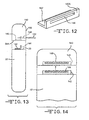
- Figs. 12 to 14 illustrate an alternate embodiment of a structure for securing a polymeric header 140 to the medical device 22.
- Polymeric header 140 is similar to the previously described header 16 except it is not molded to an undercut of a support plate. Instead, the header 20 of the medical device supports an L-shaped bracket 142, preferably of a metal such as titanium or stainless steel, having an upstanding wall 142A provided with an elongated slot 144. The longitudinal axis of slot 144 is parallel to the planar upper surface 56 of the medical device header 20.
- the bottom wall 54A of header 140 is provided with an inlet 146 that matches the shape of bracket 142.
- a lateral inlet 148 is provided in the sidewall 150 of header 140 and intersects with inlet 146.
- the bracket 142 When the molded header 140 is mounted on the medical device 22, the bracket 142 is received in the inlet 146. In this position, the lateral inlet 148 is aligned with slot 144. As shown in Fig. 13, a wedge 152, preferably of a metal such as that of the bracket 142, is moved into the lateral inlet 148 and bracket slot 144 to pin or secure the header and medical device together.
- the wedge can also be of a polymeric material.
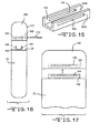
- Figs. 15 to 17 illustrate an alternate embodiment of a structure for securing a polymeric header 160, similar to the previously described header 140, to the medical device 22.
- the medical device header 20 supports a U-shaped bracket 162, preferably of a metal such as titanium or stainless steel, having a pair of upstanding sidewalls 162A and 162B, each provided with an elongated slot 164.
- the longitudinal axes of the slots 164 are parallel to the planar upper surface 56 of the medical device header 20.
- the bottom wall 54B of the molded header 160 is provided with an inlet 166 that matches the shape of bracket 162.
- a lateral inlet 168 is provided in the sidewall 170 of header 160 and intersects with inlet 164.
- the bracket 162 When the header 160 is mounted on the medical device 22, the bracket 162 is received in the inlet 166. In this position, the lateral inlet 168 is aligned with slots 164. As shown in Fig. 16, a metal or polymeric wedge 172 is moved into the lateral inlet 168 and bracket slots 164 to secure the header 160 and medical device 22 together.
Landscapes
- Health & Medical Sciences (AREA)
- Engineering & Computer Science (AREA)
- Biomedical Technology (AREA)
- Nuclear Medicine, Radiotherapy & Molecular Imaging (AREA)
- Radiology & Medical Imaging (AREA)
- Life Sciences & Earth Sciences (AREA)
- Animal Behavior & Ethology (AREA)
- General Health & Medical Sciences (AREA)
- Public Health (AREA)
- Veterinary Medicine (AREA)
- Electrotherapy Devices (AREA)
- External Artificial Organs (AREA)
Applications Claiming Priority (2)
| Application Number | Priority Date | Filing Date | Title |
|---|---|---|---|
| US42378702P | 2002-11-05 | 2002-11-05 | |
| US423787P | 2002-11-05 |
Publications (1)
| Publication Number | Publication Date |
|---|---|
| EP1417986A1 true EP1417986A1 (de) | 2004-05-12 |
Family
ID=32108169
Family Applications (1)
| Application Number | Title | Priority Date | Filing Date |
|---|---|---|---|
| EP03025398A Withdrawn EP1417986A1 (de) | 2002-11-05 | 2003-11-05 | Einstückiges Kopfstück für ein implantierbares medizinisches Gerät |
Country Status (4)
| Country | Link |
|---|---|
| US (1) | US7167749B2 (de) |
| EP (1) | EP1417986A1 (de) |
| JP (1) | JP2004283550A (de) |
| CA (1) | CA2448376A1 (de) |
Cited By (4)
| Publication number | Priority date | Publication date | Assignee | Title |
|---|---|---|---|---|
| US7489968B1 (en) | 2006-04-07 | 2009-02-10 | Pacesetter, Inc. | Pre-molded header with universal tip-to-tip feedthru adaptor |
| WO2012027126A1 (en) * | 2010-08-25 | 2012-03-01 | Cardiac Pacemakers, Inc. | Apparatus and method for attaching a header to a housing of an implantable device |
| EP2049197A4 (de) * | 2006-07-31 | 2013-03-20 | Cranial Medical Systems Inc | Mehrkanalstecker für gehirnstimulationssystem |
| WO2013142734A1 (en) | 2012-03-21 | 2013-09-26 | Bal Seal Engineering, Inc. | Connectors with electrical or signal carrying capabilities and related methods |
Families Citing this family (76)
| Publication number | Priority date | Publication date | Assignee | Title |
|---|---|---|---|---|
| JP4015934B2 (ja) * | 2002-04-18 | 2007-11-28 | 株式会社東芝 | 動画像符号化方法及び装置 |
| US7110827B2 (en) * | 2003-04-25 | 2006-09-19 | Medtronic, Inc. | Electrical connectors for medical lead having weld-less wiring connection |
| US7647111B2 (en) * | 2003-07-31 | 2010-01-12 | Medtronic, Inc. | Connector assembly for connecting a lead and an implantable medical device |
| US20050027325A1 (en) * | 2003-07-31 | 2005-02-03 | Jay Lahti | Connector assembly for connecting a lead and an implantable medical device |
| US7769458B2 (en) * | 2003-07-31 | 2010-08-03 | Medtronic, Inc. | Small format connector clip of an implantable medical device |
| US20060210131A1 (en) * | 2005-03-15 | 2006-09-21 | Wheeler Frederick W Jr | Tomographic computer aided diagnosis (CAD) with multiple reconstructions |
| US20060224208A1 (en) * | 2005-04-05 | 2006-10-05 | Bal Seal Engineering Co., Inc. | Medical electronics electrical implantable medical devices |
| US9192771B2 (en) | 2005-09-29 | 2015-11-24 | St Jude Medical Ab | Implantable medical device |
| US7567842B1 (en) * | 2005-09-29 | 2009-07-28 | Advanced Neuromodulation Systems, Inc. | Housing providing an electrical stimulation lead contact in an implantable stimulation device |
| US7682202B2 (en) * | 2005-10-28 | 2010-03-23 | Cardiac Pacemakers, Inc. | Connector assembly for implantable device |
| US7413482B2 (en) * | 2005-11-17 | 2008-08-19 | Medtronic, Inc. | Method for forming a connector assembly for use with an implantable medical device |
| DE102006003223A1 (de) * | 2005-12-08 | 2007-06-14 | Biotronik Crm Patent Ag | Gehäuse für ein medizinisches Implantat |
| DE102006003224A1 (de) * | 2005-12-08 | 2007-06-14 | Biotronik Crm Patent Ag | Gehäuse für ein medizinisches Implantat |
| US7654843B2 (en) * | 2006-02-28 | 2010-02-02 | Medtronic, Inc. | Connector assembly with internal seals and manufacturing method |
| US20080103572A1 (en) | 2006-10-31 | 2008-05-01 | Medtronic, Inc. | Implantable medical lead with threaded fixation |
| US7502217B2 (en) * | 2007-02-16 | 2009-03-10 | Medtronic, Inc. | Filtering capacitor feedthrough assembly |
| US8233986B2 (en) * | 2007-07-12 | 2012-07-31 | Medtronic, Inc. | Connector header for implantable medical device |
| US8108045B2 (en) | 2007-10-29 | 2012-01-31 | Cretex Orthopaedics, Inc. | Set screw-less pacemaker header with lead lock system |
| US8065009B2 (en) * | 2008-01-25 | 2011-11-22 | Greatbatch Ltd. | Header over-molded on a feedthrough assembly for an implantable device |
| US7563142B1 (en) * | 2008-04-30 | 2009-07-21 | Medtronic, Inc. | Medical device packaging systems including electrical interfaces |
| US8346362B2 (en) | 2008-08-13 | 2013-01-01 | Greatbatch Ltd. | Molded header connected to a medical device by lateral deformation of a sleeve/feedthrough pin sub-assembly |
| US9095728B2 (en) * | 2008-09-05 | 2015-08-04 | Medtronic, Inc. | Electrical contact for implantable medical device |
| US8096838B2 (en) | 2009-03-11 | 2012-01-17 | Bal Seal Engineering, Inc. | Header assembly for implantable medical devices |
| US8190260B2 (en) * | 2009-03-24 | 2012-05-29 | Medtronic, Inc. | Lead retention and sealing device |
| US20100249871A1 (en) * | 2009-03-24 | 2010-09-30 | Medtronic, Inc. | Full Visibility Lead Retention |
| US8032221B2 (en) * | 2009-03-24 | 2011-10-04 | Medtronic, Inc. | Sealing setscrew |
| US20110015694A1 (en) * | 2009-07-16 | 2011-01-20 | Pacesetter, Inc. | Prefabricated header for hermetically sealed device |
| WO2011017432A1 (en) | 2009-08-05 | 2011-02-10 | Medtronic, Inc. | Connector and contact assemblies for medical devices |
| US9403022B2 (en) * | 2010-01-29 | 2016-08-02 | Medtronic, Inc. | Header assembly for implantable medical device |
| US8552311B2 (en) | 2010-07-15 | 2013-10-08 | Advanced Bionics | Electrical feedthrough assembly |
| US8386047B2 (en) * | 2010-07-15 | 2013-02-26 | Advanced Bionics | Implantable hermetic feedthrough |
| US11211741B2 (en) | 2011-06-03 | 2021-12-28 | Greatbatch Ltd. | Removable terminal pin connector for an active electronics circuit board for use in an implantable medical device |
| US8593816B2 (en) | 2011-09-21 | 2013-11-26 | Medtronic, Inc. | Compact connector assembly for implantable medical device |
| US20130110204A1 (en) * | 2011-10-26 | 2013-05-02 | Pacesetter, Inc. | Spring connector for implantable medical device |
| WO2013067538A1 (en) | 2011-11-04 | 2013-05-10 | Nevro Corporation | Medical device communication and charding assemblies for use with implantable signal generators |
| US8628348B2 (en) * | 2012-05-17 | 2014-01-14 | Medtronic, Inc. | Connector module assemblies, methods, and components for implantable medical electrical devices |
| CA2882974C (en) | 2012-08-31 | 2018-10-23 | Alfred E. Mann Foundation For Scientific Research | Feedback controlled coil driver for inductive power transfer |
| US9209544B2 (en) | 2013-01-31 | 2015-12-08 | Heraeus Precious Metals Gmbh & Co. Kg | Lead connector with distal frame and method of manufacture |
| WO2014146019A2 (en) | 2013-03-15 | 2014-09-18 | Alfred E. Mann Foundation For Scientific Research | High voltage monitoring successive approximation analog to digital converter |
| CN105164920B (zh) | 2013-03-15 | 2018-02-06 | 艾尔弗雷德·E·曼科学研究基金会 | 具有快速开启时间的电流感测多输出电流刺激器 |
| US9433779B2 (en) | 2013-05-03 | 2016-09-06 | Alfred E. Mann Foundation For Scientific Research | Multi-branch stimulation electrode for subcutaneous field stimulation |
| WO2014179816A2 (en) | 2013-05-03 | 2014-11-06 | Alfred E. Mann Foundation For Scientific Research | High reliability wire welding for implantable devices |
| WO2014179685A1 (en) * | 2013-05-03 | 2014-11-06 | Nevro Corporation | Molded headers for implantable signal generators, and associated systems and methods |
| WO2014179813A1 (en) | 2013-05-03 | 2014-11-06 | Alfred E. Mann Foundtion For Scientific Research | Implant recharger handshaking system and method |
| US9855436B2 (en) | 2013-07-29 | 2018-01-02 | Alfred E. Mann Foundation For Scientific Research | High efficiency magnetic link for implantable devices |
| US9780596B2 (en) | 2013-07-29 | 2017-10-03 | Alfred E. Mann Foundation For Scientific Research | Microprocessor controlled class E driver |
| EP3145582B1 (de) | 2014-05-20 | 2020-10-21 | Nevro Corporation | Implantierte pulsgeneratoren mit reduziertem leistungsverbrauch über signalstärke-/signaldauereigenschaften sowie entsprechende systeme |
| AU2015301489B2 (en) | 2014-08-15 | 2020-01-23 | Axonics Modulation Technologies, Inc. | External pulse generator device and associated methods for trial nerve stimulation |
| WO2016025913A1 (en) | 2014-08-15 | 2016-02-18 | Axonics Modulation Technologies, Inc. | Electromyographic lead positioning and stimulation titration in a nerve stimulation system for treatment of overactive bladder |
| US9802038B2 (en) | 2014-08-15 | 2017-10-31 | Axonics Modulation Technologies, Inc. | Implantable lead affixation structure for nerve stimulation to alleviate bladder dysfunction and other indication |
| CN107073258B (zh) | 2014-08-15 | 2020-02-21 | 艾克索尼克斯调制技术股份有限公司 | 用于基于神经定位来进行神经刺激电极配置的系统和方法 |
| US9700731B2 (en) | 2014-08-15 | 2017-07-11 | Axonics Modulation Technologies, Inc. | Antenna and methods of use for an implantable nerve stimulator |
| US10682521B2 (en) | 2014-08-15 | 2020-06-16 | Axonics Modulation Technologies, Inc. | Attachment devices and associated methods of use with a nerve stimulation charging device |
| CN106999709B (zh) | 2014-08-15 | 2021-07-09 | 艾克索尼克斯股份有限公司 | 用于与可植入神经刺激器一起使用的集成肌电图临床医生程控器 |
| US9884198B2 (en) | 2014-10-22 | 2018-02-06 | Nevro Corp. | Systems and methods for extending the life of an implanted pulse generator battery |
| CN107427685B (zh) | 2015-01-09 | 2021-09-21 | 艾克索尼克斯股份有限公司 | 与神经刺激充电设备一起使用的附接设备及相关联方法 |
| WO2016112398A1 (en) | 2015-01-09 | 2016-07-14 | Axonics Modulation Technologies, Inc. | Patient remote and associated methods of use with a nerve stimulation system |
| US9517344B1 (en) | 2015-03-13 | 2016-12-13 | Nevro Corporation | Systems and methods for selecting low-power, effective signal delivery parameters for an implanted pulse generator |
| US9943685B2 (en) | 2015-04-23 | 2018-04-17 | Cyberonics, Inc. | Lead engagement devices and methods for electrical stimulation and/or monitoring systems |
| AU2016291554B2 (en) | 2015-07-10 | 2021-01-07 | Axonics Modulation Technologies, Inc. | Implantable nerve stimulator having internal electronics without ASIC and methods of use |
| US10195423B2 (en) | 2016-01-19 | 2019-02-05 | Axonics Modulation Technologies, Inc. | Multichannel clip device and methods of use |
| US9517338B1 (en) | 2016-01-19 | 2016-12-13 | Axonics Modulation Technologies, Inc. | Multichannel clip device and methods of use |
| WO2017132374A1 (en) | 2016-01-29 | 2017-08-03 | Axonics Modulation Technologies, Inc. | Methods and systems for frequency adjustment to optimize charging of implantable neurostimulator |
| AU2017218157B2 (en) | 2016-02-12 | 2022-09-29 | Axonics, Inc. | External pulse generator device and associated methods for trial nerve stimulation |
| JP7677791B2 (ja) | 2018-02-22 | 2025-05-15 | アクソニクス インコーポレイテッド | 試験的神経刺激のための神経刺激リードおよび使用方法 |
| EP3603741A1 (de) * | 2018-08-02 | 2020-02-05 | BIOTRONIK SE & Co. KG | Implantat und verfahren zum herstellen einer elektrischen verbindung zwischen einem elektronikmodul und einer elektronischen komponente eines implantats |
| US10933238B2 (en) | 2019-01-31 | 2021-03-02 | Nevro Corp. | Power control circuit for sterilized devices, and associated systems and methods |
| US11642537B2 (en) | 2019-03-11 | 2023-05-09 | Axonics, Inc. | Charging device with off-center coil |
| US11439829B2 (en) | 2019-05-24 | 2022-09-13 | Axonics, Inc. | Clinician programmer methods and systems for maintaining target operating temperatures |
| WO2020242900A1 (en) | 2019-05-24 | 2020-12-03 | Axonics Modulation Technologies, Inc. | Trainer device for a neurostimulator programmer and associated methods of use with a neurostimulation system |
| US12218458B2 (en) | 2020-03-05 | 2025-02-04 | Greatbatch Ltd. | High-voltage electrical insulation for use in active implantable medical devices circuit board connectors |
| EP3943031B1 (de) | 2020-07-24 | 2025-02-12 | Greatbatch Ltd. | Kopfverbindungssystem für implantierbare medizinische vorrichtung |
| EP3950047B1 (de) | 2020-07-27 | 2024-10-16 | Heraeus Medical Components, LLC | Leitungsverbinder mit montagerahmen und verfahren zur herstellung |
| US12420103B1 (en) | 2020-08-20 | 2025-09-23 | Axonics, Inc. | Neurostimulation leads with reduced current leakage |
| CN119013078A (zh) | 2022-01-03 | 2024-11-22 | 爱颂尼科公司 | 用于神经刺激器的接插件和天线 |
| USD1019950S1 (en) * | 2022-01-03 | 2024-03-26 | Axonics, Inc. | Header for an implantable medical device |
Citations (6)
| Publication number | Priority date | Publication date | Assignee | Title |
|---|---|---|---|---|
| US4182345A (en) * | 1978-04-07 | 1980-01-08 | Medtronic, Inc. | Body implantable signal generator assembly |
| US5070605A (en) * | 1988-04-22 | 1991-12-10 | Medtronic, Inc. | Method for making an in-line pacemaker connector system |
| US5076270A (en) * | 1990-05-03 | 1991-12-31 | Siemens-Pacesetter, Inc. | Apparatus and method for making electrical connections in an implantable pacemaker |
| US5086773A (en) * | 1990-09-10 | 1992-02-11 | Cardiac Pacemakers, Inc. | Tool-less pacemaker lead assembly |
| US5336246A (en) * | 1993-06-23 | 1994-08-09 | Telectronics Pacing Systems, Inc. | Lead connector assembly for medical device and method of assembly |
| US5871514A (en) * | 1997-08-01 | 1999-02-16 | Medtronic, Inc. | Attachment apparatus for an implantable medical device employing ultrasonic energy |
Family Cites Families (20)
| Publication number | Priority date | Publication date | Assignee | Title |
|---|---|---|---|---|
| US4010760A (en) * | 1975-05-23 | 1977-03-08 | Medtronic, Inc. | Coupling assembly for implantable electromedical devices |
| US4010759A (en) * | 1975-08-29 | 1977-03-08 | Vitatron Medical B.V. | Insulated, corrosion resistant medical electronic devices and method for producing same |
| US4041956A (en) * | 1976-02-17 | 1977-08-16 | Coratomic, Inc. | Pacemakers of low weight and method of making such pacemakers |
| US4057068A (en) * | 1976-02-20 | 1977-11-08 | Medtronic, Inc. | Enclosure for and method of enclosing a body implantable pulse generator |
| ES479225A1 (es) | 1978-04-07 | 1979-12-01 | Medtronic Inc | Perfeccimonamientos en apratos estimuladores implantables en el cuerpo, con un nuevo conectador. |
| US4254775A (en) * | 1979-07-02 | 1981-03-10 | Mieczyslaw Mirowski | Implantable defibrillator and package therefor |
| US4262673A (en) * | 1979-10-11 | 1981-04-21 | Mieczyslaw Mirowski | Fluid tight coupling for electrode lead |
| FR2502502A1 (fr) * | 1981-03-27 | 1982-10-01 | Cardiofrance Co | Stimulateur cardiaque comportant une enceinte unique de separation des moyens generateurs de courant electrique et de production d'impulsions |
| US4764132A (en) * | 1986-03-28 | 1988-08-16 | Siemens-Pacesetter, Inc. | Pacemaker connector block for proximal ring electrode |
| US5235742A (en) * | 1989-11-20 | 1993-08-17 | Siemens Pacesetter, Inc. | Method of making an implantable device |
| US5103818A (en) * | 1990-11-13 | 1992-04-14 | Siemens-Pacesetter, Inc. | System and method for completing electrical connections in an implantable medical device |
| US5662692A (en) * | 1994-12-09 | 1997-09-02 | Pacesetter, Inc. | Cardiac defibrillator having selectable polarity case |
| US5549653A (en) * | 1995-09-22 | 1996-08-27 | Intermedics, Inc. | Muscle stimulation electrode for implantable cardial stimulation device with warning system |
| DE19622669A1 (de) * | 1996-06-05 | 1997-12-11 | Implex Gmbh | Implantierbare Einheit |
| US5643328A (en) * | 1996-07-19 | 1997-07-01 | Sulzer Intermedics Inc. | Implantable cardiac stimulation device with warning system having elongated stimulation electrode |
| US5741313A (en) * | 1996-09-09 | 1998-04-21 | Pacesetter, Inc. | Implantable medical device with a reduced volumetric configuration and improved shock stabilization |
| US5980973A (en) * | 1998-03-13 | 1999-11-09 | Medtronic, Inc. | Implantable medical device with biocompatible surface and method for its manufacture |
| US6026325A (en) * | 1998-06-18 | 2000-02-15 | Pacesetter, Inc. | Implantable medical device having an improved packaging system and method for making electrical connections |
| US6052623A (en) * | 1998-11-30 | 2000-04-18 | Medtronic, Inc. | Feedthrough assembly for implantable medical devices and methods for providing same |
| US6817905B2 (en) * | 2000-06-20 | 2004-11-16 | Medtronic, Inc. | Connector assembly for an implantable medical device and process for making |
-
2003
- 2003-11-05 JP JP2003375467A patent/JP2004283550A/ja active Pending
- 2003-11-05 US US10/701,849 patent/US7167749B2/en not_active Expired - Lifetime
- 2003-11-05 EP EP03025398A patent/EP1417986A1/de not_active Withdrawn
- 2003-11-05 CA CA002448376A patent/CA2448376A1/en not_active Abandoned
Patent Citations (6)
| Publication number | Priority date | Publication date | Assignee | Title |
|---|---|---|---|---|
| US4182345A (en) * | 1978-04-07 | 1980-01-08 | Medtronic, Inc. | Body implantable signal generator assembly |
| US5070605A (en) * | 1988-04-22 | 1991-12-10 | Medtronic, Inc. | Method for making an in-line pacemaker connector system |
| US5076270A (en) * | 1990-05-03 | 1991-12-31 | Siemens-Pacesetter, Inc. | Apparatus and method for making electrical connections in an implantable pacemaker |
| US5086773A (en) * | 1990-09-10 | 1992-02-11 | Cardiac Pacemakers, Inc. | Tool-less pacemaker lead assembly |
| US5336246A (en) * | 1993-06-23 | 1994-08-09 | Telectronics Pacing Systems, Inc. | Lead connector assembly for medical device and method of assembly |
| US5871514A (en) * | 1997-08-01 | 1999-02-16 | Medtronic, Inc. | Attachment apparatus for an implantable medical device employing ultrasonic energy |
Cited By (7)
| Publication number | Priority date | Publication date | Assignee | Title |
|---|---|---|---|---|
| US7489968B1 (en) | 2006-04-07 | 2009-02-10 | Pacesetter, Inc. | Pre-molded header with universal tip-to-tip feedthru adaptor |
| US8214046B2 (en) | 2006-04-07 | 2012-07-03 | Pacesetter, Inc. | Pre-molded header with universal tip-to-tip feedthru adaptor |
| EP2049197A4 (de) * | 2006-07-31 | 2013-03-20 | Cranial Medical Systems Inc | Mehrkanalstecker für gehirnstimulationssystem |
| WO2012027126A1 (en) * | 2010-08-25 | 2012-03-01 | Cardiac Pacemakers, Inc. | Apparatus and method for attaching a header to a housing of an implantable device |
| US8585445B2 (en) | 2010-08-25 | 2013-11-19 | Cardiac Pacemakers, Inc. | Apparatus and method for attaching a header to a housing of an implantable device |
| WO2013142734A1 (en) | 2012-03-21 | 2013-09-26 | Bal Seal Engineering, Inc. | Connectors with electrical or signal carrying capabilities and related methods |
| EP2828937A4 (de) * | 2012-03-21 | 2015-11-11 | Bal Seal Engineering Inc | Verbinder mit elektrischen oder signaltragenden fähigkeiten und zugehörige verfahren |
Also Published As
| Publication number | Publication date |
|---|---|
| JP2004283550A (ja) | 2004-10-14 |
| US7167749B2 (en) | 2007-01-23 |
| US20040093038A1 (en) | 2004-05-13 |
| CA2448376A1 (en) | 2004-05-05 |
Similar Documents
| Publication | Publication Date | Title |
|---|---|---|
| US7167749B2 (en) | One piece header assembly for an implantable medical device | |
| US7069081B2 (en) | One piece header assembly for an implantable medical device | |
| US8706229B2 (en) | Connector assembly for connecting a lead and an implantable medical device | |
| US8204596B2 (en) | Isolation connector for an intravascular implantable medical device | |
| US6895276B2 (en) | In-line lead header for an implantable medical device | |
| EP1962948B1 (de) | Drahtverbindungen und verstärkung | |
| US7647111B2 (en) | Connector assembly for connecting a lead and an implantable medical device | |
| JP4533380B2 (ja) | 植込み型医療装置の小型の形態のコネクタクリップ | |
| US20050043771A1 (en) | Multi-polar electrical medical lead connector system | |
| US20230372721A1 (en) | Strain-Relief/Lead Assembly Electrically And Mechanically Connected To An Active Medical Device |
Legal Events
| Date | Code | Title | Description |
|---|---|---|---|
| PUAI | Public reference made under article 153(3) epc to a published international application that has entered the european phase |
Free format text: ORIGINAL CODE: 0009012 |
|
| AK | Designated contracting states |
Kind code of ref document: A1 Designated state(s): AT BE BG CH CY CZ DE DK EE ES FI FR GB GR HU IE IT LI LU MC NL PT RO SE SI SK TR |
|
| AX | Request for extension of the european patent |
Extension state: AL LT LV MK |
|
| 17P | Request for examination filed |
Effective date: 20041108 |
|
| AKX | Designation fees paid |
Designated state(s): AT BE BG CH CY CZ DE DK EE ES FI FR GB GR HU IE IT LI LU MC NL PT RO SE SI SK TR |
|
| 17Q | First examination report despatched |
Effective date: 20050524 |
|
| GRAP | Despatch of communication of intention to grant a patent |
Free format text: ORIGINAL CODE: EPIDOSNIGR1 |
|
| STAA | Information on the status of an ep patent application or granted ep patent |
Free format text: STATUS: THE APPLICATION HAS BEEN WITHDRAWN |
|
| 18W | Application withdrawn |
Effective date: 20070713 |