EP1418395A2 - Refrigeration system - Google Patents
Refrigeration system Download PDFInfo
- Publication number
- EP1418395A2 EP1418395A2 EP03023993A EP03023993A EP1418395A2 EP 1418395 A2 EP1418395 A2 EP 1418395A2 EP 03023993 A EP03023993 A EP 03023993A EP 03023993 A EP03023993 A EP 03023993A EP 1418395 A2 EP1418395 A2 EP 1418395A2
- Authority
- EP
- European Patent Office
- Prior art keywords
- low pressure
- pressure refrigerant
- high pressure
- collection reservoir
- low
- Prior art date
- Legal status (The legal status is an assumption and is not a legal conclusion. Google has not performed a legal analysis and makes no representation as to the accuracy of the status listed.)
- Withdrawn
Links
Images


Classifications
-
- F—MECHANICAL ENGINEERING; LIGHTING; HEATING; WEAPONS; BLASTING
- F25—REFRIGERATION OR COOLING; COMBINED HEATING AND REFRIGERATION SYSTEMS; HEAT PUMP SYSTEMS; MANUFACTURE OR STORAGE OF ICE; LIQUEFACTION SOLIDIFICATION OF GASES
- F25B—REFRIGERATION MACHINES, PLANTS OR SYSTEMS; COMBINED HEATING AND REFRIGERATION SYSTEMS; HEAT PUMP SYSTEMS
- F25B41/00—Fluid-circulation arrangements
-
- F—MECHANICAL ENGINEERING; LIGHTING; HEATING; WEAPONS; BLASTING
- F25—REFRIGERATION OR COOLING; COMBINED HEATING AND REFRIGERATION SYSTEMS; HEAT PUMP SYSTEMS; MANUFACTURE OR STORAGE OF ICE; LIQUEFACTION SOLIDIFICATION OF GASES
- F25B—REFRIGERATION MACHINES, PLANTS OR SYSTEMS; COMBINED HEATING AND REFRIGERATION SYSTEMS; HEAT PUMP SYSTEMS
- F25B40/00—Subcoolers, desuperheaters or superheaters
-
- F—MECHANICAL ENGINEERING; LIGHTING; HEATING; WEAPONS; BLASTING
- F25—REFRIGERATION OR COOLING; COMBINED HEATING AND REFRIGERATION SYSTEMS; HEAT PUMP SYSTEMS; MANUFACTURE OR STORAGE OF ICE; LIQUEFACTION SOLIDIFICATION OF GASES
- F25B—REFRIGERATION MACHINES, PLANTS OR SYSTEMS; COMBINED HEATING AND REFRIGERATION SYSTEMS; HEAT PUMP SYSTEMS
- F25B43/00—Arrangements for separating or purifying gases or liquids; Arrangements for vaporising the residuum of liquid refrigerant, e.g. by heat
- F25B43/006—Accumulators
-
- F—MECHANICAL ENGINEERING; LIGHTING; HEATING; WEAPONS; BLASTING
- F28—HEAT EXCHANGE IN GENERAL
- F28D—HEAT-EXCHANGE APPARATUS, NOT PROVIDED FOR IN ANOTHER SUBCLASS, IN WHICH THE HEAT-EXCHANGE MEDIA DO NOT COME INTO DIRECT CONTACT
- F28D7/00—Heat-exchange apparatus having stationary tubular conduit assemblies for both heat-exchange media, the media being in contact with different sides of a conduit wall
- F28D7/0008—Heat-exchange apparatus having stationary tubular conduit assemblies for both heat-exchange media, the media being in contact with different sides of a conduit wall the conduits for one medium being in heat conductive contact with the conduits for the other medium
-
- F—MECHANICAL ENGINEERING; LIGHTING; HEATING; WEAPONS; BLASTING
- F28—HEAT EXCHANGE IN GENERAL
- F28D—HEAT-EXCHANGE APPARATUS, NOT PROVIDED FOR IN ANOTHER SUBCLASS, IN WHICH THE HEAT-EXCHANGE MEDIA DO NOT COME INTO DIRECT CONTACT
- F28D7/00—Heat-exchange apparatus having stationary tubular conduit assemblies for both heat-exchange media, the media being in contact with different sides of a conduit wall
- F28D7/0008—Heat-exchange apparatus having stationary tubular conduit assemblies for both heat-exchange media, the media being in contact with different sides of a conduit wall the conduits for one medium being in heat conductive contact with the conduits for the other medium
- F28D7/0025—Heat-exchange apparatus having stationary tubular conduit assemblies for both heat-exchange media, the media being in contact with different sides of a conduit wall the conduits for one medium being in heat conductive contact with the conduits for the other medium the conduits for one medium or the conduits for both media being flat tubes or arrays of tubes
- F28D7/0033—Heat-exchange apparatus having stationary tubular conduit assemblies for both heat-exchange media, the media being in contact with different sides of a conduit wall the conduits for one medium being in heat conductive contact with the conduits for the other medium the conduits for one medium or the conduits for both media being flat tubes or arrays of tubes the conduits for one medium or the conduits for both media being bent
-
- F—MECHANICAL ENGINEERING; LIGHTING; HEATING; WEAPONS; BLASTING
- F25—REFRIGERATION OR COOLING; COMBINED HEATING AND REFRIGERATION SYSTEMS; HEAT PUMP SYSTEMS; MANUFACTURE OR STORAGE OF ICE; LIQUEFACTION SOLIDIFICATION OF GASES
- F25B—REFRIGERATION MACHINES, PLANTS OR SYSTEMS; COMBINED HEATING AND REFRIGERATION SYSTEMS; HEAT PUMP SYSTEMS
- F25B2400/00—Component parts or details not otherwise provided for in this subclass
- F25B2400/05—Compression system with heat exchange between particular parts of the system
- F25B2400/051—Compression system with heat exchange between particular parts of the system between the accumulator and another part of the cycle
-
- F—MECHANICAL ENGINEERING; LIGHTING; HEATING; WEAPONS; BLASTING
- F25—REFRIGERATION OR COOLING; COMBINED HEATING AND REFRIGERATION SYSTEMS; HEAT PUMP SYSTEMS; MANUFACTURE OR STORAGE OF ICE; LIQUEFACTION SOLIDIFICATION OF GASES
- F25B—REFRIGERATION MACHINES, PLANTS OR SYSTEMS; COMBINED HEATING AND REFRIGERATION SYSTEMS; HEAT PUMP SYSTEMS
- F25B2500/00—Problems to be solved
- F25B2500/18—Optimization, e.g. high integration of refrigeration components
Definitions
- This invention pertains to refrigeration systems that include a suction line heat exchanger and an accumulator. Particularly, the invention relates to integrated units having a suction line heat exchanger positioned within a reservoir of a suction line accumulator.
- Refrigeration systems for use in automobile cooling and home refrigeration applications are comprised of several components.
- such refrigeration systems contain a series of process units including compressors, condensers, evaporators, expansion devices, suction line heat exchangers, and liquid accumulators.
- compressors condensers, evaporators, expansion devices, suction line heat exchangers, and liquid accumulators.
- suction line heat exchanger and liquid accumulator functions of these processes are integrated into one unit.
- an integrated unit for use in a refrigeration system having a refrigerant loop with a high-pressure refrigerant flowing through a portion of the loop to reject heat from the system and a low-pressure refrigerant flowing through another portion of the loop to absorb heat to the system.
- the integrated unit includes a housing having a collection reservoir for the refrigerant; a low pressure flat tube extending into the collection reservoir to direct the low pressure refrigerant therethrough; and a high pressure flat tube extending into the collection reservoir to direct the high pressure refrigerant therethrough.
- a broad side of the low pressure flat tube and a broad side of the high pressure flat tube are in close heat exchange relation to each other within the collection reservoir.
- an integrated unit in a refrigeration system includes a housing having a collection reservoir, a low pressure refrigerant inlet port, a low pressure refrigerant outlet port, a high pressure refrigerant inlet port and a high pressure refrigerant outlet port; a low pressure conduit connected in the housing to the low pressure refrigerant outlet port to direct low pressure refrigerant from the collection reservoir to the low pressure refrigerant outlet port; a high pressure conduit extending in the housing from the high pressure refrigerant inlet port to the high pressure refrigerant outlet port; and a plurality of heat exchange fins extending from the high pressure conduit and the low pressure conduit in the collection reservoir. Each fin is in close heat exchange relation with both the high pressure conduit and the low pressure conduit.
- the low-pressure conduit and the high-pressure conduit are flat tubes.
- the low-pressure flat tube and the high-pressure flat tube are in close heat exchange relation to each other.
- the low-pressure flat tube and the high-pressure flat tube have longitudinal axes extending parallel to each other.
- the plurality of heat exchange fins extend transversely from both the high-pressure conduit and low pressure conduit in the collection reservoir.
- the integrated unit further includes at least one slot in each fin that receives both tubes.
- each slot is open to an edge of the fin to allow assembly of the fins onto the tubes.
- the integrated unit comprises a housing having a collection reservoir, a low pressure refrigerant inlet port, a low pressure refrigerant outlet port, a high pressure refrigerant inlet port, a high pressure refrigerant outlet port; a low pressure conduit connected in the housing to the low pressure refrigerant outlet port to direct low pressure refrigerant from the collection reservoir to the low pressure refrigerant outlet port; a high pressure conduit extending in the housing from the high pressure refrigerant inlet port to the high pressure refrigerant outlet port; and at least one heat exchange fin extending between a first leg of the high-pressure conduit and a second leg of the high-pressure conduit in the collection reservoir and fin being in conductive heat exchange relation with the high-pressure conduit.
- an integrated unit in a refrigeration system includes a housing having a collection reservoir, a low pressure refrigerant inlet port, a low pressure refrigerant outlet port, a high pressure refrigerant inlet port and a high pressure refrigerant outlet port; a low pressure conduit with an outside surface and a longitudinal axis, the low pressure conduit extending in the collection reservoir and connected to the low pressure refrigerant outlet port to direct low pressure refrigerant from the collection reservoir to the low pressure refrigerant outlet port; and a high pressure conduit with an outside surface and a longitudinal axis, the high pressure conduit extending in the collection reservoir from the high pressure refrigerant inlet port to the high pressure refrigerant outlet port.
- the longitudinal axes extend parallel to one another over a length and the outside surfaces are in close heat exchange relation.
- outside surfaces are in direct contact with one another.
- the integrated unit comprising a plurality of heat exchange fins extending transversely from the high pressure conduit and from the low pressure conduit, each fin in close heat exchange relation with both the high pressure conduit and the low pressure conduit.
- FIG. 1 Another embodiment of the invention is a refrigeration system including a compressor to compress a refrigerant; a heat exchanger to reject heat from the compressed refrigerant; an expansion device to expand the compressed refrigerant; an evaporator to transfer heat to the refrigerant; and an integrated suction line heat exchanger and accumulator.
- the integrated suction line heat exchanger and accumulator includes a collection reservoir; a low pressure flat tube extending into the collection reservoir to direct the expanded refrigerant therethrough; and a high pressure flat tube extending into the collection reservoir to direct the compressed refrigerant therethrough.
- a broad side of the low pressure flat tube and a broad side of the high pressure flat tube are in conductive heat exchange relation within the housing.
- a refrigeration system comprising a compressor to compress a refrigerant; a heat exchanger to reject heat from the compressed refrigerant; an expansion device to expand the compressed refrigerant; an evaporator to transfer heat to the refrigerant; and an integrated suction line heat exchanger and accumulator.
- the integrated suction line heat exchanger and accumulator includes a collection reservoir; a low pressure refrigerant inlet port; a low pressure refrigerant outlet port; a high pressure refrigerant inlet port and a high pressure refrigerant outlet port; a low pressure conduit connected in the housing to the low pressure refrigerant outlet port to direct the expanded refrigerant from the collection reservoir to the low pressure refrigerant outlet port; a high pressure conduit extending in the housing from the high pressure refrigerant inlet port to the high pressure refrigerant outlet port; and a plurality of heat exchange fins extending from the high pressure conduit and the low pressure conduits in the collection reservoir, each fin in conductive heat exchange relation with both the high pressure line and the low pressure line.
- a refrigeration system comprises a compressor to compress a refrigerant; a heat exchanger to reject heat from the compressed refrigerant; an expansion device to expand the compressed refrigerant; an evaporator to transfer heat to the refrigerant; and an integrated suction line heat exchanger and accumulator.
- the integrated suction line heat exchanger and accumulator includes a collection reservoir; a low pressure refrigerant inlet port, a low pressure refrigerant outlet port; a high pressure refrigerant inlet port; a high pressure refrigerant outlet port; a low pressure conduit with an outside surface and a longitudinal axis and connected in the collection reservoir to the low pressure refrigerant outlet port to direct the expanded refrigerant from the collection reservoir to the low pressure refrigerant outlet port; and a high pressure conduit with an outside surface and a longitudinal axis.
- the high pressure conduit extends in the collection reservoir from the high pressure refrigerant inlet port to the high pressure refrigerant outlet port.
- the longitudinal axes extend parallel to one another over a length and the outside surfaces are in close heat exchange relation.
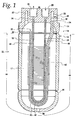
- FIG. 1 An integrated suction line heat exchanger and accumulator unit 10 embodying the present invention is represented in Figure 1.
- a housing 12 connects a cap 14 on one end and a reservoir cap 16 on the opposite end from the cap 14 to enclose a collection reservoir or chamber 17 within the unit 10 to receive low pressure refrigerant and separate the refrigerant into its liquid and vapor phases.
- a low-pressure conduit 18 directs the flow of a low-pressure refrigerant within the housing 12 in the direction of the arrow 20 through a low-pressure refrigerant inlet port 22 which in the illustrated embodiment is an open end of the tube.
- the low-pressure refrigerant enters the low-pressure refrigerant inlet port 22 in the direction depicted by the arrow 20 and flows through the low-pressure conduit 18 to a low-pressure refrigerant outlet port 24 which in the illustrated embodiment is an open end of the tube.
- the low-pressure refrigerant exits the integrated unit 10 through a port 25 in the cap 14 as indicated by the arrow 26.
- the cap 14 also contains a port 27 to direct low pressure refrigerant into the chamber 17.
- the cap 14 contains two portals 28, 30 that fluidly connect a high pressure refrigerant inlet port 32 and a high pressure refrigerant outlet port 34 to other units of the refrigeration system in which the integrated unit 10 is used.
- the ports 32, 34 are open ends of the high-pressure conduit 36 which loops through the housing 12.
- the high-pressure refrigerant flows through the high-pressure conduit 36 in the direction indicated by the arrow 38 from the high-pressure refrigerant inlet port 32 to the high pressure refrigerant outlet port 34 .
- the refrigerant within the low-pressure conduit 18 and high-pressure conduit 36 is in a countercurrent flow configuration.
- the low-pressure conduit 18 and the high-pressure conduit 36 may be tubes with a circular cross-section, but are preferably flat tubes.
- both the low-pressure conduit 18 and the high-pressure conduit 36 have longitudinal axes 40, 42 respectively.
- the longitudinal axes 40, 42 extend parallel to one another, preferably over at least a majority of their lengths 44 within the housing 12 .
- the low-pressure conduit 18 has an outside surface 46 and the high-pressure conduit 36 has an outside surface 48 with the surfaces 46 and 48 facing each other with a conductive heat path therebetween. It is preferable that the low-pressure conduit 18 and the high-pressure conduit 36 are in contact over the entire area or substantially the entire area of the surfaces 46, 48 over the length 44 .
- direct contact may not be possible over the entire length 44 , or that there may be another conductive path between the two conduits 18, 36 .
- direct contact between the outside surfaces 46, 48 may not always be required for adequate heat exchange.
- the surfaces 46, 48 may be placed close to one another with a heat conductive material sandwiched therebetween such that they are in conductive heat exchange relation.
- a plurality of heat exchange fins 50 may extend from the high pressure conduit 36 and the low pressure conduit 18, with each fin 50 being in a conductive heat exchange relation with both the low pressure conduit 18 and the high pressure conduit 36.
- the fins 50 have slots 52 formed therein, with the slots 52 forming openings 54 that allow the fins 50 to slide onto the conduits 18 , 36 with the conduits 18, 36 and the fins 50 assembled as a unit.
- the sides of the slots 52 contact the corresponding sides of the conduits 18, 36 and are bonded thereto using a suitable bonding technique such as brazing or soldering.
- the fins 50 also have flanges 56 to provide guidance of the unit of fins 50 onto the conduits 18, 36 and to further assist in the conduction of heat between the conduits 18, 36 and the fins 50.
- the integrated unit 10 can be constructed without the fins 50. However, when the fins 50 are included in the unit 10, the fins 50 assist in heat transfer from the high pressure refrigerant in the high-pressure conduit 36 to the low pressure refrigerant in the chamber 17.
- the fins 50 may be, for example, the plate fins 50 depicted in Figures 1, 2 and 4 or may be a serpentine fin 57 as depicted in Figures 3 and 5.
- the serpentine fin 57 is in conductive heat exchange relation with a first leg 58 and a second leg 59 of the high-pressure conduit 36.
- the fin 57 contacts the legs 58, 59 and is bonded thereto using a suitable bonding technique, such as brazing.
- the serpentine fin 57 may be folded horizontally between the first leg 58 and the second leg 59 of the high-pressure conduit 36 as depicted in Figure 5 or may be folded vertically (not shown). While one fin 57 is shown, there may be some applications where more than one fin 57 is desirable.
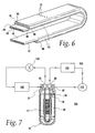
- Figure 6 depicts the relationship between a low-pressure multi-port flat tube 18 and a high-pressure multi-port flat tube 36 used in the integrated unit 10 described herein.
- Multi-port flat tubes are preferred in high pressure transcritical cooling systems which often use carbon dioxide as a refrigerant, because they are able to withstand the higher pressures at which such systems operate while providing superior heat transfer performance.
- the low-pressure multi-port flat tube 18 and high-pressure multi-port flat tube 36 may be a single piece produced by coextrusion or may be separate pieces that are closely aligned in conductive heat exchange relation as shown.
- the low-pressure flat tube 18 has a row of flow passages 60 , however, the low-pressure tube may also be a single port low pressure tube.
- the high-pressure flat tube 36 has a row of internal flow passages 62, and preferably, the flow passages 60 of the low-pressure flat tube 18 are of a larger cross-sectional area than the flow passages 62 of high-pressure flat tube 36.
- the low-pressure flat tube 18 has a broad outside surface 46 that contacts a broad outside surface 48 of the high pressure flat tube 36.
- the low pressure flat tube 18 has an extension 68 of a narrow side 70 that partially wraps around a narrow side 72 of the high pressure flat tube 36 .
- the extension 68 may be included on the opposite narrow side 70 of the low pressure tube 36 to further assist in locating the tubes 18, 36 relative to each other.
- similar extension may be located on the high pressure tube 36 to wrap around the narrow sides 70 of the low pressure flat tube 18 for the same purpose and effect.
- holes 73 that open to one or more of the passages 60 may be provided in an upper region of the tube 18 to allow liquid refrigerant that may gather in the upper region of the chamber 17 to be metered into the tube 18 by the vapor refrigerant flow therein.
- each flow passage 60 contains a hole 73 .
- one or more small holes that open to the flow passages 60 may be provided at the bottom of the low pressure conduit 18 to allow oil that has been separated from the liquid refrigerant and gathered at the bottom of the chamber 17 to be drawn into the low pressure refrigerant stream exiting the integrated unit 10 via the flow passages 60.
- a drain port 80 may be provided at the bottom of the chamber 17 so that separated oil can be reintroduced to the cooling system via a suitable conduit.
- FIG. 7 depicts an example of a typical refrigeration system 100 in which the integrated unit 10 may be used.
- the system 100 has a compressor 110 for compressing the refrigerant; a heat exchanger 120 , that is typically a condenser or gas cooler, to reject heat from the refrigerant generated by the compressor 110 , an expansion device 130 to expand the compressed refrigerant, and an evaporator 140 to transfer heat to the expanded refrigerant.
- a compressor 110 for compressing the refrigerant
- a heat exchanger 120 that is typically a condenser or gas cooler, to reject heat from the refrigerant generated by the compressor 110
- an expansion device 130 to expand the compressed refrigerant
- an evaporator 140 to transfer heat to the expanded refrigerant.
- the integrated unit 10 serves the purpose of separating liquid phase refrigerant from the vapor phase refrigerant prior to the vapor phase refrigerant entering the compressor 110.
- Liquid refrigerant accumulates in the lower part of the chamber 17 of the refrigerant integrated unit 10 .
- Heat is transferred to the low pressure refrigerant in the chamber 17 and the low-pressure conduit 18 from the high pressure refrigerant in the high-pressure conduit 36, thereby assisting in the vaporization of any liquid refrigerant within the unit 10 before the low pressure refrigerant exits the unit 10 via the low-pressure conduit 18.
- the above described heat transfer in the integrated unit 10 also cools the high pressure refrigerant in the high-pressure conduit 36 prior to the refrigerant entering the expansion devices 130, which can improve the overall performance of the cooling system.
- the housing 12 and caps 14 and 16 are a three piece, substantially cylindrical construction, but in some applications other constructions, such as two piece and/or non-cylindrical, may be desired.
- plate fins 50 are shown, other types of fins may be desirable in certain applications. The inventors expect skilled artisans to employ such variations as appropriate, and the inventors intend for the invention to be practiced otherwise than as specifically described herein. Accordingly, this invention includes all modifications and equivalents of the subject matter recited in the claims appended hereto as permitted by applicable law. Moreover, any combination of the above-described elements in all possible variations thereof is encompassed by the invention unless otherwise indicated herein or otherwise clearly contradicted by context.
Landscapes
- Engineering & Computer Science (AREA)
- Physics & Mathematics (AREA)
- Thermal Sciences (AREA)
- Mechanical Engineering (AREA)
- General Engineering & Computer Science (AREA)
- Chemical & Material Sciences (AREA)
- Analytical Chemistry (AREA)
- Power Engineering (AREA)
- Heat-Exchange Devices With Radiators And Conduit Assemblies (AREA)
- Arrangement Or Mounting Of Propulsion Units For Vehicles (AREA)
- Cooling Or The Like Of Semiconductors Or Solid State Devices (AREA)
Abstract
Description
- This invention pertains to refrigeration systems that include a suction line heat exchanger and an accumulator. Particularly, the invention relates to integrated units having a suction line heat exchanger positioned within a reservoir of a suction line accumulator.
- Refrigeration systems for use in automobile cooling and home refrigeration applications are comprised of several components. Generally, such refrigeration systems contain a series of process units including compressors, condensers, evaporators, expansion devices, suction line heat exchangers, and liquid accumulators. In order to conserve space within the cooling and refrigeration systems, reduce costs and reduce the number of fittings required, and to make the systems more compact, several applications have integrated the suction line heat exchanger and liquid accumulator functions of these processes into one unit.
- Two examples of an integrated heat exchange unit and accumulators are given in U.S. Patent Nos. 2,467,078 and 2,530,648. In these patents, a coiled tube is wrapped around a straight tube for heat exchange between the two tubes within an accumulator. In another example, U.S. Patent No. 3,163,998, heat exchange fins are closely associated with a tube that encircles a length of low pressure tubing that is withdrawing vapor from an accumulator to provide heat exchange advantages. In U.S. Patent No. 6,298,687, concentric tubing is used within a collection unit. While at least some of these integrated units may perform satisfactorily for their intended purpose, there is always room for improvement.
- In one embodiment, an integrated unit is provided for use in a refrigeration system having a refrigerant loop with a high-pressure refrigerant flowing through a portion of the loop to reject heat from the system and a low-pressure refrigerant flowing through another portion of the loop to absorb heat to the system. The integrated unit includes a housing having a collection reservoir for the refrigerant; a low pressure flat tube extending into the collection reservoir to direct the low pressure refrigerant therethrough; and a high pressure flat tube extending into the collection reservoir to direct the high pressure refrigerant therethrough. A broad side of the low pressure flat tube and a broad side of the high pressure flat tube are in close heat exchange relation to each other within the collection reservoir.
- In another embodiment, an integrated unit in a refrigeration system includes a housing having a collection reservoir, a low pressure refrigerant inlet port, a low pressure refrigerant outlet port, a high pressure refrigerant inlet port and a high pressure refrigerant outlet port; a low pressure conduit connected in the housing to the low pressure refrigerant outlet port to direct low pressure refrigerant from the collection reservoir to the low pressure refrigerant outlet port; a high pressure conduit extending in the housing from the high pressure refrigerant inlet port to the high pressure refrigerant outlet port; and a plurality of heat exchange fins extending from the high pressure conduit and the low pressure conduit in the collection reservoir. Each fin is in close heat exchange relation with both the high pressure conduit and the low pressure conduit.
- In a further embodiment of the integrated unit, the low-pressure conduit and the high-pressure conduit are flat tubes.
- In a further embodiment, the low-pressure flat tube and the high-pressure flat tube are in close heat exchange relation to each other.
- In yet a further embodiment, the low-pressure flat tube and the high-pressure flat tube have longitudinal axes extending parallel to each other.
- In still a further embodiment, the plurality of heat exchange fins extend transversely from both the high-pressure conduit and low pressure conduit in the collection reservoir.
- In another embodiment, the integrated unit further includes at least one slot in each fin that receives both tubes. In a further embodiment, each slot is open to an edge of the fin to allow assembly of the fins onto the tubes.
- In another embodiment, the integrated unit comprises a housing having a collection reservoir, a low pressure refrigerant inlet port, a low pressure refrigerant outlet port, a high pressure refrigerant inlet port, a high pressure refrigerant outlet port; a low pressure conduit connected in the housing to the low pressure refrigerant outlet port to direct low pressure refrigerant from the collection reservoir to the low pressure refrigerant outlet port; a high pressure conduit extending in the housing from the high pressure refrigerant inlet port to the high pressure refrigerant outlet port; and at least one heat exchange fin extending between a first leg of the high-pressure conduit and a second leg of the high-pressure conduit in the collection reservoir and fin being in conductive heat exchange relation with the high-pressure conduit.
- In another embodiment, an integrated unit in a refrigeration system includes a housing having a collection reservoir, a low pressure refrigerant inlet port, a low pressure refrigerant outlet port, a high pressure refrigerant inlet port and a high pressure refrigerant outlet port; a low pressure conduit with an outside surface and a longitudinal axis, the low pressure conduit extending in the collection reservoir and connected to the low pressure refrigerant outlet port to direct low pressure refrigerant from the collection reservoir to the low pressure refrigerant outlet port; and a high pressure conduit with an outside surface and a longitudinal axis, the high pressure conduit extending in the collection reservoir from the high pressure refrigerant inlet port to the high pressure refrigerant outlet port. In the collection reservoir the longitudinal axes extend parallel to one another over a length and the outside surfaces are in close heat exchange relation.
- In a further embodiment, the outside surfaces are in direct contact with one another.
- In yet a further embodiment, the integrated unit comprising a plurality of heat exchange fins extending transversely from the high pressure conduit and from the low pressure conduit, each fin in close heat exchange relation with both the high pressure conduit and the low pressure conduit.
- Another embodiment of the invention is a refrigeration system including a compressor to compress a refrigerant; a heat exchanger to reject heat from the compressed refrigerant; an expansion device to expand the compressed refrigerant; an evaporator to transfer heat to the refrigerant; and an integrated suction line heat exchanger and accumulator. The integrated suction line heat exchanger and accumulator includes a collection reservoir; a low pressure flat tube extending into the collection reservoir to direct the expanded refrigerant therethrough; and a high pressure flat tube extending into the collection reservoir to direct the compressed refrigerant therethrough. A broad side of the low pressure flat tube and a broad side of the high pressure flat tube are in conductive heat exchange relation within the housing.
- In another embodiment is a refrigeration system comprising a compressor to compress a refrigerant; a heat exchanger to reject heat from the compressed refrigerant; an expansion device to expand the compressed refrigerant; an evaporator to transfer heat to the refrigerant; and an integrated suction line heat exchanger and accumulator. The integrated suction line heat exchanger and accumulator includes a collection reservoir; a low pressure refrigerant inlet port; a low pressure refrigerant outlet port; a high pressure refrigerant inlet port and a high pressure refrigerant outlet port; a low pressure conduit connected in the housing to the low pressure refrigerant outlet port to direct the expanded refrigerant from the collection reservoir to the low pressure refrigerant outlet port; a high pressure conduit extending in the housing from the high pressure refrigerant inlet port to the high pressure refrigerant outlet port; and a plurality of heat exchange fins extending from the high pressure conduit and the low pressure conduits in the collection reservoir, each fin in conductive heat exchange relation with both the high pressure line and the low pressure line.
- In yet another embodiment, a refrigeration system comprises a compressor to compress a refrigerant; a heat exchanger to reject heat from the compressed refrigerant; an expansion device to expand the compressed refrigerant; an evaporator to transfer heat to the refrigerant; and an integrated suction line heat exchanger and accumulator. The integrated suction line heat exchanger and accumulator includes a collection reservoir; a low pressure refrigerant inlet port, a low pressure refrigerant outlet port; a high pressure refrigerant inlet port; a high pressure refrigerant outlet port; a low pressure conduit with an outside surface and a longitudinal axis and connected in the collection reservoir to the low pressure refrigerant outlet port to direct the expanded refrigerant from the collection reservoir to the low pressure refrigerant outlet port; and a high pressure conduit with an outside surface and a longitudinal axis. The high pressure conduit extends in the collection reservoir from the high pressure refrigerant inlet port to the high pressure refrigerant outlet port. In the collection reservoir, the longitudinal axes extend parallel to one another over a length and the outside surfaces are in close heat exchange relation.
-
- Figure 1 is a cross-sectional view of an embodiment of the integrated suction line heat exchanger and accumulator unit of the present invention.
- Figure 2 is an exploded perspective view of the embodiment of the integrated unit depicted in Figure 1.
- Figure 3 is an exploded perspective view of another embodiment of the integrated unit of the present invention.
- Figure 4 is a perspective view of an embodiment of the integrated unit of the present invention with the housing of the accumulator removed.
- Figure 5 is a perspective view of an embodiment of the integrated unit of the present invention with the housing of the accumulator removed.
- Figure 6 depicts the close heat exchange relation between the flat tubes of an embodiment of the present invention.
- Figure 7 is a schematic representation of a refrigeration system in which the integrated suction line heat exchanger and accumulator units of the present invention may be used.
-
- An integrated suction line heat exchanger and
accumulator unit 10 embodying the present invention is represented in Figure 1. Ahousing 12 connects acap 14 on one end and areservoir cap 16 on the opposite end from thecap 14 to enclose a collection reservoir orchamber 17 within theunit 10 to receive low pressure refrigerant and separate the refrigerant into its liquid and vapor phases. A low-pressure conduit 18 directs the flow of a low-pressure refrigerant within thehousing 12 in the direction of thearrow 20 through a low-pressurerefrigerant inlet port 22 which in the illustrated embodiment is an open end of the tube. The low-pressure refrigerant enters the low-pressurerefrigerant inlet port 22 in the direction depicted by thearrow 20 and flows through the low-pressure conduit 18 to a low-pressurerefrigerant outlet port 24 which in the illustrated embodiment is an open end of the tube. The low-pressure refrigerant exits the integratedunit 10 through aport 25 in thecap 14 as indicated by thearrow 26. Thecap 14 also contains aport 27 to direct low pressure refrigerant into thechamber 17. - The
cap 14 contains twoportals refrigerant inlet port 32 and a high pressurerefrigerant outlet port 34 to other units of the refrigeration system in which the integratedunit 10 is used. In the illustrated embodiment, theports pressure conduit 36 which loops through thehousing 12. The high-pressure refrigerant flows through the high-pressure conduit 36 in the direction indicated by thearrow 38 from the high-pressurerefrigerant inlet port 32 to the high pressurerefrigerant outlet port 34. Preferably, the refrigerant within the low-pressure conduit 18 and high-pressure conduit 36 is in a countercurrent flow configuration. - The low-
pressure conduit 18 and the high-pressure conduit 36 may be tubes with a circular cross-section, but are preferably flat tubes. Within thehousing 12, both the low-pressure conduit 18 and the high-pressure conduit 36 have longitudinal axes 40, 42 respectively. The longitudinal axes 40, 42 extend parallel to one another, preferably over at least a majority of theirlengths 44 within thehousing 12. The low-pressure conduit 18 has anoutside surface 46 and the high-pressure conduit 36 has anoutside surface 48 with thesurfaces pressure conduit 18 and the high-pressure conduit 36 are in contact over the entire area or substantially the entire area of thesurfaces length 44. However, is should be appreciated that direct contact may not be possible over theentire length 44, or that there may be another conductive path between the twoconduits outside surfaces surfaces - Optionally, a plurality of
heat exchange fins 50 may extend from thehigh pressure conduit 36 and thelow pressure conduit 18, with eachfin 50 being in a conductive heat exchange relation with both thelow pressure conduit 18 and thehigh pressure conduit 36. Preferably, thefins 50 haveslots 52 formed therein, with theslots 52 formingopenings 54 that allow thefins 50 to slide onto theconduits conduits fins 50 assembled as a unit. Preferably, the sides of theslots 52 contact the corresponding sides of theconduits fins 50 also haveflanges 56 to provide guidance of the unit offins 50 onto theconduits conduits fins 50. Theintegrated unit 10 can be constructed without thefins 50. However, when thefins 50 are included in theunit 10, thefins 50 assist in heat transfer from the high pressure refrigerant in the high-pressure conduit 36 to the low pressure refrigerant in thechamber 17. Thefins 50 may be, for example, theplate fins 50 depicted in Figures 1, 2 and 4 or may be aserpentine fin 57 as depicted in Figures 3 and 5. Theserpentine fin 57 is in conductive heat exchange relation with afirst leg 58 and asecond leg 59 of the high-pressure conduit 36. Preferably, thefin 57 contacts thelegs serpentine fin 57 may be folded horizontally between thefirst leg 58 and thesecond leg 59 of the high-pressure conduit 36 as depicted in Figure 5 or may be folded vertically (not shown). While onefin 57 is shown, there may be some applications where more than onefin 57 is desirable. - Figure 6 depicts the relationship between a low-pressure multi-port
flat tube 18 and a high-pressure multi-portflat tube 36 used in theintegrated unit 10 described herein. Multi-port flat tubes are preferred in high pressure transcritical cooling systems which often use carbon dioxide as a refrigerant, because they are able to withstand the higher pressures at which such systems operate while providing superior heat transfer performance. The low-pressure multi-portflat tube 18 and high-pressure multi-portflat tube 36 may be a single piece produced by coextrusion or may be separate pieces that are closely aligned in conductive heat exchange relation as shown. The low-pressureflat tube 18 has a row offlow passages 60, however, the low-pressure tube may also be a single port low pressure tube. The high-pressureflat tube 36 has a row ofinternal flow passages 62, and preferably, theflow passages 60 of the low-pressureflat tube 18 are of a larger cross-sectional area than theflow passages 62 of high-pressureflat tube 36. The low-pressureflat tube 18 has a broadoutside surface 46 that contacts a broadoutside surface 48 of the high pressureflat tube 36. As an optional feature, the low pressureflat tube 18 has anextension 68 of anarrow side 70 that partially wraps around anarrow side 72 of the high pressureflat tube 36. Theextension 68 may be included on the oppositenarrow side 70 of thelow pressure tube 36 to further assist in locating thetubes high pressure tube 36 to wrap around thenarrow sides 70 of the low pressureflat tube 18 for the same purpose and effect. As another option holes 73 that open to one or more of thepassages 60 may be provided in an upper region of thetube 18 to allow liquid refrigerant that may gather in the upper region of thechamber 17 to be metered into thetube 18 by the vapor refrigerant flow therein. Preferably, when holes 73 are present in the low-pressure multi-portflat tube 18, eachflow passage 60 contains ahole 73. - As another option, one or more small holes (not shown) that open to the
flow passages 60 may be provided at the bottom of thelow pressure conduit 18 to allow oil that has been separated from the liquid refrigerant and gathered at the bottom of thechamber 17 to be drawn into the low pressure refrigerant stream exiting theintegrated unit 10 via theflow passages 60. Further, adrain port 80 may be provided at the bottom of thechamber 17 so that separated oil can be reintroduced to the cooling system via a suitable conduit. - Figure 7 depicts an example of a
typical refrigeration system 100 in which theintegrated unit 10 may be used. Thesystem 100 has acompressor 110 for compressing the refrigerant; aheat exchanger 120, that is typically a condenser or gas cooler, to reject heat from the refrigerant generated by thecompressor 110, anexpansion device 130 to expand the compressed refrigerant, and anevaporator 140 to transfer heat to the expanded refrigerant. - The
integrated unit 10 serves the purpose of separating liquid phase refrigerant from the vapor phase refrigerant prior to the vapor phase refrigerant entering thecompressor 110. Liquid refrigerant accumulates in the lower part of thechamber 17 of the refrigerantintegrated unit 10. Heat is transferred to the low pressure refrigerant in thechamber 17 and the low-pressure conduit 18 from the high pressure refrigerant in the high-pressure conduit 36, thereby assisting in the vaporization of any liquid refrigerant within theunit 10 before the low pressure refrigerant exits theunit 10 via the low-pressure conduit 18. This reduces the possibility that slugs of liquid refrigerant will be passed to thecompressor 110, which can damage thecompressor 110. Furthermore, the above described heat transfer in theintegrated unit 10 also cools the high pressure refrigerant in the high-pressure conduit 36 prior to the refrigerant entering theexpansion devices 130, which can improve the overall performance of the cooling system. - The use of any and all examples, or exemplary language (e.g., "such as" or "for example") provided herein, is intended merely to better illuminate the invention and does not pose a limitation on the scope of the invention unless recited in a claim. While some potential advantages and objects have been expressly identified herein, it should be understood that some embodiments of the invention may not provide all, or any, of the expressly identified advantages and objects. Preferred embodiments of this invention are described herein, including the best mode known to the inventors for carrying out the invention. Of course, variations of those preferred embodiments will become apparent to those of ordinary skill in the art upon reading the foregoing description. For example, the
housing 12 and caps 14 and 16 are a three piece, substantially cylindrical construction, but in some applications other constructions, such as two piece and/or non-cylindrical, may be desired. As another example, whileplate fins 50 are shown, other types of fins may be desirable in certain applications. The inventors expect skilled artisans to employ such variations as appropriate, and the inventors intend for the invention to be practiced otherwise than as specifically described herein. Accordingly, this invention includes all modifications and equivalents of the subject matter recited in the claims appended hereto as permitted by applicable law. Moreover, any combination of the above-described elements in all possible variations thereof is encompassed by the invention unless otherwise indicated herein or otherwise clearly contradicted by context.
Claims (16)
- An integrated unit in a refrigeration system having a refrigerant loop with a high pressure refrigerant flowing through a portion of the loop to reject heat from the system and a low pressure refrigerant flowing through another portion of the loop to absorb heat to the system, the unit comprising:wherein a broad side of the low pressure flat tube and a broad side of the high pressure flat tube are in conductive heat exchange relation to each other within the collection reservoir.a housing having a collection reservoir for the refrigerant;a low pressure flat tube extending into the collection reservoir to direct the low pressure refrigerant therethrough; anda high-pressure flat tube extending into the collection reservoir to direct the high pressure refrigerant therethrough;
- An integrated unit in a refrigeration system, the unit comprising:a housing having a collection reservoir, a low pressure refrigerant inlet port, a low pressure refrigerant outlet port, a high pressure refrigerant inlet port and a high pressure refrigerant outlet port;a low pressure conduit connected in the housing to the low pressure refrigerant outlet port to direct low pressure refrigerant from the collection reservoir to the low pressure refrigerant outlet port;a high pressure conduit extending in the housing from the high pressure refrigerant inlet port to the high pressure refrigerant outlet port; anda plurality of heat exchange fins extending from the high-pressure conduit and the low-pressure conduit in the collection reservoir, each fin is in conductive heat exchange relation with both the high-pressure conduit and the low-pressure conduit.
- The integrated unit of claim 2 wherein the low pressure conduit and the high pressure conduit are flat tubes.
- The integrated unit of claim 3 wherein the low-pressure flat tube and the high pressure flat tube are in conductive heat exchange relation to each other.
- The integrated unit of claim 3 wherein the low pressure flat tube and the high pressure flat tube have longitudinal axes extending parallel to each other.
- The integrated unit of claim 2 wherein the plurality of heat exchange fins extend transversely from both the high-pressure conduit and low-pressure conduit in the collection reservoir.
- The integrated unit of claim 2 further comprising at least one slot in each fin to receive both tubes.
- The integrated unit of claim 7 wherein each slot is open to an edge of the fin to allow assembly of the fins onto the tubes.
- An integrated unit in a refrigeration system, the unit comprising:a housing having a collection reservoir, a low pressure refrigerant inlet port, a low pressure refrigerant outlet port, a high pressure refrigerant inlet port and a high pressure refrigerant outlet port;a low pressure conduit connected in the housing to the low pressure refrigerant outlet port to direct low pressure refrigerant from the collection reservoir to the low pressure refrigerant outlet port;a high pressure conduit extending in the housing from the high pressure refrigerant inlet port to the high pressure refrigerant outlet port; andat least one of heat exchange fin extending between a first leg of the high-pressure conduit and a second leg of the high-pressure conduit in the collection reservoir and being in conductive heat exchange relation with the high-pressure conduit.
- The integrated unit of claim 9 wherein the at least one fin is a serpentine fin.
- An integrated unit in a refrigeration system, the unit comprising:wherein in the collection reservoir the longitudinal axes extend parallel to one another over a length and the outside surfaces are in conductive heat exchange relation.a housing having a collection reservoir, a low pressure refrigerant inlet port, a low pressure refrigerant outlet port, a high pressure refrigerant inlet port and a high pressure refrigerant outlet port;a low pressure conduit with an outside surface and a longitudinal axis, the low pressure conduit extending in the collection reservoir and connected to the low pressure refrigerant outlet port to direct low pressure refrigerant from the collection reservoir to the low pressure refrigerant outlet port; anda high pressure conduit with an outside surface and a longitudinal axis, the high pressure conduit extending in the collection reservoir from the high pressure refrigerant inlet port to the high pressure refrigerant outlet port;
- The integrated unit of claim 11 wherein the outside surfaces are in direct contact with one another.
- The integrated unit of claim 11 further comprising a plurality of heat exchange fins extending transversely from the high-pressure conduit and from the low-pressure conduit, each fin in conductive heat exchange relation with both the high-pressure conduit and the low-pressure conduit.
- A refrigeration system comprising:wherein a broad side of the low pressure flat tube and a broad side of the high pressure flat tube are in conductive heat exchange relation within the housing.a compressor to compress a refrigerant;a heat exchanger to reject heat from the compressed refrigerant;an expansion device to expand the compressed refrigerant;an evaporator to transfer heat to the refrigerant; andan integrated suction line heat exchanger and accumulator, the integrated suction line heat exchanger and accumulator including a collection reservoir, a low pressure flat tube extending into the collection reservoir to direct the expanded refrigerant therethrough, and a high pressure flat tube extending into the collection reservoir to direct the compressed refrigerant therethrough;
- A refrigeration system comprising:a compressor to compress a refrigerant;a heat exchanger to reject heat from the compressed refrigerant;an expansion device to expand the compressed refrigerant;an evaporator to transfer heat to the refrigerant;an integrated suction line heat exchanger and accumulator, the integrated suction line heat exchanger and accumulator having a collection reservoir; a low pressure refrigerant inlet port, a low pressure refrigerant outlet port, a high pressure refrigerant inlet port and a high pressure refrigerant outlet port, a low pressure conduit connected in the housing to the low pressure refrigerant outlet port to direct the expanded refrigerant from the collection reservoir to the low pressure refrigerant outlet port, a high pressure conduit extending in the housing from the high pressure refrigerant inlet port to the high pressure refrigerant outlet port; anda plurality of heat exchange fins extending from the high-pressure conduit and the low-pressure conduits in the collection reservoir, each fin in conductive heat exchange relation with both the high-pressure line and the low-pressure line.
- A refrigeration system comprising:wherein in the collection reservoir the longitudinal axes extend parallel to one another over a length and the outside surfaces are in conductive heat exchange relation.a compressor to compress a refrigerant;a heat exchanger to reject heat from the compressed refrigerant;an expansion device to expand the compressed refrigerant;an evaporator to transfer heat to the refrigerant; andan integrated suction line heat exchanger and accumulator, the integrated suction line heat exchanger and accumulator having a collection reservoir; a low pressure refrigerant inlet port, a low pressure refrigerant outlet port, a high pressure refrigerant inlet port and a high pressure refrigerant outlet port, a low pressure conduit with an outside surface and a longitudinal axis and connected in the collection reservoir to the low pressure refrigerant outlet port to direct the expanded refrigerant from the collection reservoir to the low pressure refrigerant outlet port, and a high pressure conduit with an outside surface and a longitudinal axis, the high pressure conduit extends in the collection reservoir from the high pressure refrigerant inlet port to the high pressure refrigerant outlet port;
Applications Claiming Priority (2)
| Application Number | Priority Date | Filing Date | Title |
|---|---|---|---|
| US10/287,388 US6681597B1 (en) | 2002-11-04 | 2002-11-04 | Integrated suction line heat exchanger and accumulator |
| US287388 | 2002-11-04 |
Publications (2)
| Publication Number | Publication Date |
|---|---|
| EP1418395A2 true EP1418395A2 (en) | 2004-05-12 |
| EP1418395A3 EP1418395A3 (en) | 2006-01-11 |
Family
ID=30115354
Family Applications (1)
| Application Number | Title | Priority Date | Filing Date |
|---|---|---|---|
| EP03023993A Withdrawn EP1418395A3 (en) | 2002-11-04 | 2003-10-22 | Refrigeration system |
Country Status (11)
| Country | Link |
|---|---|
| US (1) | US6681597B1 (en) |
| EP (1) | EP1418395A3 (en) |
| JP (1) | JP2004156896A (en) |
| KR (1) | KR20040040354A (en) |
| CN (1) | CN100501275C (en) |
| AU (1) | AU2003257526A1 (en) |
| BR (1) | BR0304584A (en) |
| CA (1) | CA2444892A1 (en) |
| DE (1) | DE03023993T1 (en) |
| MX (1) | MXPA03009168A (en) |
| RU (1) | RU2003132145A (en) |
Cited By (3)
| Publication number | Priority date | Publication date | Assignee | Title |
|---|---|---|---|---|
| FR2930018A1 (en) * | 2008-04-15 | 2009-10-16 | Valeo Systemes Thermiques | COMBINED DEVICE COMPRISING AN INTERNAL HEAT EXCHANGER AND AN ACCUMULATOR. |
| CN102803871A (en) * | 2009-06-12 | 2012-11-28 | 陈玪洙 | Liquid receiver combined with liquid separator for refrigeration cycle and manufacturing method thereof |
| US12392532B2 (en) | 2022-06-07 | 2025-08-19 | Carrier Corporation | Accumulator heat exchanger |
Families Citing this family (39)
| Publication number | Priority date | Publication date | Assignee | Title |
|---|---|---|---|---|
| US6901763B2 (en) * | 2003-06-24 | 2005-06-07 | Modine Manufacturing Company | Refrigeration system |
| JP4400332B2 (en) * | 2004-06-18 | 2010-01-20 | 株式会社デンソー | Air conditioner for vehicles |
| US7685839B2 (en) * | 2004-07-09 | 2010-03-30 | Junjie Gu | Refrigeration system |
| JP2006273049A (en) * | 2005-03-28 | 2006-10-12 | Calsonic Kansei Corp | Vehicular air conditioner |
| US20060236716A1 (en) * | 2005-04-21 | 2006-10-26 | Griffin Gary E | Refrigerant accumulator |
| DE102005021464A1 (en) | 2005-05-10 | 2006-11-16 | Modine Manufacturing Co., Racine | Intermediate heat exchanger for air-conditioning loop, has heat exchange ribs filling compartment between tube and two opposing walls, where refrigerant flowing through compartment does not flow through large space |
| DE102005021787A1 (en) * | 2005-05-11 | 2006-11-16 | Modine Manufacturing Co., Racine | Transcritical air-conditioning refrigerant e.g. carbon-di-oxide, treating apparatus for use in e.g. automobile, has flat multi-chamber tube extruded to extend straight over length of vessel |
| JP4897298B2 (en) * | 2006-01-17 | 2012-03-14 | サンデン株式会社 | Gas-liquid separator module |
| US8434227B2 (en) | 2006-01-19 | 2013-05-07 | Modine Manufacturing Company | Method of forming heat exchanger tubes |
| JP2007298259A (en) * | 2006-05-08 | 2007-11-15 | Sanden Corp | Gas-liquid separator module |
| JP4842022B2 (en) * | 2006-06-14 | 2011-12-21 | サンデン株式会社 | Vapor compression refrigeration circuit and vehicle air conditioning system using the circuit |
| KR100784611B1 (en) * | 2006-08-18 | 2007-12-11 | 주식회사 두원공조 | Gas-liquid separator with internal heat exchanger of cooling system |
| DE102007004993A1 (en) * | 2007-02-01 | 2008-08-07 | Modine Manufacturing Co., Racine | Production process for flat tubes and roller mill |
| FR2916263B1 (en) | 2007-05-16 | 2009-07-31 | Hutchinson Sa | ACCUMULATOR FOR INTERNAL THERMAL EXCHANGER TYPE AIR CONDITIONING CIRCUIT AND INCORPORATING CIRCUIT |
| FR2928997B1 (en) * | 2008-03-20 | 2014-06-20 | Valeo Systemes Thermiques | HEAT EXCHANGER AND INTEGRATED AIR CONDITIONING ASSEMBLY COMPRISING SUCH AN EXCHANGER. |
| JP5153664B2 (en) * | 2009-01-16 | 2013-02-27 | 三菱電機株式会社 | Waste heat regeneration system |
| US9702602B2 (en) * | 2009-04-23 | 2017-07-11 | Gary E Phillippe | Method and apparatus for improving refrigeration and air conditioning efficiency |
| DE202010014128U1 (en) * | 2010-10-12 | 2011-02-24 | Tranter Pressko Gmbh | Assembly of heat exchanger and liquid separator |
| US20120102989A1 (en) | 2010-10-27 | 2012-05-03 | Honeywell International Inc. | Integrated receiver and suction line heat exchanger for refrigerant systems |
| DE102011014954A1 (en) * | 2011-03-24 | 2012-09-27 | Airbus Operations Gmbh | Storage arrangement for storing refrigerant and method for operating such a memory arrangement |
| CN102287955B (en) * | 2011-07-15 | 2012-12-12 | 中国水产科学研究院渔业机械仪器研究所 | Fishing-boat diesel-engine residual-heat ammonia-water absorption-type refrigerating system and operating mode thereof |
| JP6087359B2 (en) * | 2011-09-09 | 2017-03-01 | セルン − ヨーロピアン オーガナイゼーション フォー ニュークリア リサーチCERN − European Organization for Nuclear Research | Mini cooling system and method for accurate temperature control |
| JP5403039B2 (en) * | 2011-11-30 | 2014-01-29 | ダイキン工業株式会社 | Air conditioner |
| KR101109634B1 (en) | 2011-12-16 | 2012-01-31 | 인제대학교 산학협력단 | Accumulator with Heat Exchanger |
| CA2771113A1 (en) * | 2012-03-08 | 2012-05-22 | Serge Dube | Co2 refrigeration system for ice-playing surface |
| US10101067B2 (en) * | 2013-12-04 | 2018-10-16 | Bosch Automotive Service Solutions Llc | Heat exchanger for a refrigerant service system |
| JP6184314B2 (en) * | 2013-12-19 | 2017-08-23 | 三菱電機株式会社 | Accumulator and air conditioner |
| EP2963362A1 (en) * | 2014-06-30 | 2016-01-06 | Eaton Industrial IP GmbH & Co. KG | Accumulator for an air conditioning system |
| CN105805990A (en) * | 2014-12-29 | 2016-07-27 | 浙江三花汽车零部件有限公司 | Carbon dioxide air-conditioning system and gas-liquid separator thereof |
| DE102017109309A1 (en) * | 2017-05-02 | 2018-11-08 | Hanon Systems | Air conditioning system of a motor vehicle and method for operating the air conditioning system |
| DE102017218973A1 (en) * | 2017-10-24 | 2019-04-25 | Hanon Systems | Counterflow heat exchanger |
| US10845106B2 (en) * | 2017-12-12 | 2020-11-24 | Rheem Manufacturing Company | Accumulator and oil separator |
| US11009275B2 (en) * | 2018-10-12 | 2021-05-18 | Rheem Manufacturing Company | Compressor protection against liquid slug |
| EP3748269A1 (en) * | 2019-06-05 | 2020-12-09 | Valeo Systemes Thermiques | A heat exchanger |
| CN118565117A (en) * | 2020-04-30 | 2024-08-30 | 浙江三花智能控制股份有限公司 | Gas-liquid separation device |
| DE102021201509B4 (en) | 2021-02-17 | 2022-11-17 | Hanon Systems | Combination of a refrigerant accumulator and an internal refrigerant heat exchanger |
| US12372276B2 (en) * | 2021-09-07 | 2025-07-29 | Hill Phoenix, Inc. | Oil management in refrigeration systems |
| US12560363B2 (en) | 2023-04-21 | 2026-02-24 | Trane International Inc. | Heat pump having a charge management receiver |
| DE102023128873A1 (en) * | 2023-10-20 | 2025-04-24 | Stiebel Eltron Gmbh & Co. Kg | Collector and heat pump |
Family Cites Families (19)
| Publication number | Priority date | Publication date | Assignee | Title |
|---|---|---|---|---|
| US2467078A (en) | 1946-02-11 | 1949-04-12 | Harry Alter Company | Combination accumulator, metering tube, and heat exchanger for refrigeration systems |
| US2530648A (en) | 1946-09-26 | 1950-11-21 | Harry Alter Company | Combination accumulator, heat exchanger, and metering device for refrigerating systems |
| US2819592A (en) * | 1952-03-04 | 1958-01-14 | Sterling F Smith | Accumulator heat exchanger |
| US2740263A (en) * | 1953-04-06 | 1956-04-03 | Richard W Kritzer | Feed control means for refrigerating apparatus |
| US2990698A (en) | 1959-07-06 | 1961-07-04 | Revco Inc | Refrigeration apparatus |
| US3163998A (en) | 1962-09-06 | 1965-01-05 | Recold Corp | Refrigerant flow control apparatus |
| US3621673A (en) * | 1969-12-08 | 1971-11-23 | Trane Co | Air-conditioning system with combined chiller and accumulator |
| US3765192A (en) * | 1972-08-17 | 1973-10-16 | D Root | Evaporator and/or condenser for refrigeration or heat pump systems |
| US3955375A (en) | 1974-08-14 | 1976-05-11 | Virginia Chemicals Inc. | Combination liquid trapping suction accumulator and evaporator pressure regulator device including a capillary cartridge and heat exchanger |
| US4217765A (en) * | 1979-06-04 | 1980-08-19 | Atlantic Richfield Company | Heat exchanger-accumulator |
| US4537045A (en) * | 1984-12-07 | 1985-08-27 | Westinghouse Electric Corp. | Combination refrigerant receiver, accumulator and heat exchanger |
| US5242015A (en) * | 1991-08-22 | 1993-09-07 | Modine Manufacturing Co. | Heat exchanger |
| JP4006861B2 (en) | 1998-12-09 | 2007-11-14 | 株式会社デンソー | Integrated heat exchanger |
| DE19903833A1 (en) | 1999-02-01 | 2000-08-03 | Behr Gmbh & Co | Integrated collector heat exchanger assembly |
| US6185957B1 (en) * | 1999-09-07 | 2001-02-13 | Modine Manufacturing Company | Combined evaporator/accumulator/suctionline heat exchanger |
| US6321602B1 (en) * | 1999-09-28 | 2001-11-27 | Rockwell Science Center, Llc | Condition based monitoring by vibrational analysis |
| US6460358B1 (en) * | 2000-11-13 | 2002-10-08 | Thomas H. Hebert | Flash gas and superheat eliminator for evaporators and method therefor |
| US6523365B2 (en) * | 2000-12-29 | 2003-02-25 | Visteon Global Technologies, Inc. | Accumulator with internal heat exchanger |
| JP2003336974A (en) * | 2002-05-20 | 2003-11-28 | Toyo Radiator Co Ltd | Regenerative heat exchanger |
-
2002
- 2002-11-04 US US10/287,388 patent/US6681597B1/en not_active Expired - Fee Related
-
2003
- 2003-10-08 MX MXPA03009168A patent/MXPA03009168A/en unknown
- 2003-10-09 CA CA002444892A patent/CA2444892A1/en not_active Abandoned
- 2003-10-22 EP EP03023993A patent/EP1418395A3/en not_active Withdrawn
- 2003-10-22 DE DE03023993T patent/DE03023993T1/en active Pending
- 2003-10-23 AU AU2003257526A patent/AU2003257526A1/en not_active Abandoned
- 2003-10-24 BR BR0304584-6A patent/BR0304584A/en not_active IP Right Cessation
- 2003-10-29 JP JP2003368702A patent/JP2004156896A/en active Pending
- 2003-10-31 KR KR1020030076935A patent/KR20040040354A/en not_active Withdrawn
- 2003-11-03 RU RU2003132145/06A patent/RU2003132145A/en not_active Application Discontinuation
- 2003-11-04 CN CNB2003101045923A patent/CN100501275C/en not_active Expired - Fee Related
Non-Patent Citations (1)
| Title |
|---|
| None * |
Cited By (4)
| Publication number | Priority date | Publication date | Assignee | Title |
|---|---|---|---|---|
| FR2930018A1 (en) * | 2008-04-15 | 2009-10-16 | Valeo Systemes Thermiques | COMBINED DEVICE COMPRISING AN INTERNAL HEAT EXCHANGER AND AN ACCUMULATOR. |
| EP2110624A1 (en) | 2008-04-15 | 2009-10-21 | Valeo Systèmes Thermiques | Combined device comprising an internal heat exchanger and an accumulator |
| CN102803871A (en) * | 2009-06-12 | 2012-11-28 | 陈玪洙 | Liquid receiver combined with liquid separator for refrigeration cycle and manufacturing method thereof |
| US12392532B2 (en) | 2022-06-07 | 2025-08-19 | Carrier Corporation | Accumulator heat exchanger |
Also Published As
| Publication number | Publication date |
|---|---|
| MXPA03009168A (en) | 2004-05-10 |
| US6681597B1 (en) | 2004-01-27 |
| BR0304584A (en) | 2004-08-31 |
| AU2003257526A1 (en) | 2004-05-20 |
| KR20040040354A (en) | 2004-05-12 |
| CN1499159A (en) | 2004-05-26 |
| RU2003132145A (en) | 2005-04-10 |
| EP1418395A3 (en) | 2006-01-11 |
| CN100501275C (en) | 2009-06-17 |
| JP2004156896A (en) | 2004-06-03 |
| DE03023993T1 (en) | 2004-10-21 |
| CA2444892A1 (en) | 2004-05-04 |
Similar Documents
| Publication | Publication Date | Title |
|---|---|---|
| US6681597B1 (en) | Integrated suction line heat exchanger and accumulator | |
| EP1083395B1 (en) | Combined evaporator/accumulator/suction line heat exchanger | |
| KR100893169B1 (en) | Heat exchanger module | |
| US8099978B2 (en) | Evaporator unit | |
| EP1870648B1 (en) | Ejector type refrigerating cycle unit | |
| KR101054784B1 (en) | Carbon dioxide cooling system | |
| US10935288B2 (en) | Condenser | |
| JPH08110125A (en) | Liquid receiver integrated type refrigerant condenser and manufacture thereof | |
| US20080041093A1 (en) | Accumulator of air conditioner | |
| JP3617083B2 (en) | Receiver integrated refrigerant condenser | |
| JP2827404B2 (en) | Refrigerant condenser | |
| JPH1019421A (en) | Refrigeration cycle and accumulator used for this cycle | |
| KR101385194B1 (en) | A Condenser | |
| US20080190122A1 (en) | Accumulator Integration with Heat Exchanger Header | |
| US20060288733A1 (en) | Evaporator refrigeration system vehicle equipped with said system and method of evaporating refrigerant | |
| JP2004190955A (en) | Condenser | |
| JP2008309434A (en) | Accumulator | |
| JPH10213356A (en) | Refrigeration cycle device | |
| JPH02293570A (en) | Refrigerant condenser | |
| JPH0610763U (en) | Refrigeration cycle equipment | |
| WO2020123653A1 (en) | Refrigerant condenser | |
| JP2003065637A (en) | Vapor compression refrigeration cycle | |
| HK1122352A (en) | Accumulator integration with exchanger header |
Legal Events
| Date | Code | Title | Description |
|---|---|---|---|
| PUAI | Public reference made under article 153(3) epc to a published international application that has entered the european phase |
Free format text: ORIGINAL CODE: 0009012 |
|
| AK | Designated contracting states |
Kind code of ref document: A2 Designated state(s): AT BE BG CH CY CZ DE DK EE ES FI FR GB GR HU IE IT LI LU MC NL PT RO SE SI SK TR |
|
| AX | Request for extension of the european patent |
Extension state: AL LT LV MK |
|
| DET | De: translation of patent claims | ||
| EL | Fr: translation of claims filed | ||
| PUAL | Search report despatched |
Free format text: ORIGINAL CODE: 0009013 |
|
| AK | Designated contracting states |
Kind code of ref document: A3 Designated state(s): AT BE BG CH CY CZ DE DK EE ES FI FR GB GR HU IE IT LI LU MC NL PT RO SE SI SK TR |
|
| AX | Request for extension of the european patent |
Extension state: AL LT LV MK |
|
| 17P | Request for examination filed |
Effective date: 20060711 |
|
| AKX | Designation fees paid |
Designated state(s): DE FR |
|
| 17Q | First examination report despatched |
Effective date: 20070111 |
|
| STAA | Information on the status of an ep patent application or granted ep patent |
Free format text: STATUS: THE APPLICATION IS DEEMED TO BE WITHDRAWN |
|
| 18D | Application deemed to be withdrawn |
Effective date: 20100920 |