EP1422450A2 - Hydraulische, radial wirkende Kupplungselemente für Stufenschaltgetriebe - Google Patents
Hydraulische, radial wirkende Kupplungselemente für Stufenschaltgetriebe Download PDFInfo
- Publication number
- EP1422450A2 EP1422450A2 EP02008470A EP02008470A EP1422450A2 EP 1422450 A2 EP1422450 A2 EP 1422450A2 EP 02008470 A EP02008470 A EP 02008470A EP 02008470 A EP02008470 A EP 02008470A EP 1422450 A2 EP1422450 A2 EP 1422450A2
- Authority
- EP
- European Patent Office
- Prior art keywords
- oil
- gear
- shaft
- elements
- hose
- Prior art date
- Legal status (The legal status is an assumption and is not a legal conclusion. Google has not performed a legal analysis and makes no representation as to the accuracy of the status listed.)
- Withdrawn
Links
- 230000005540 biological transmission Effects 0.000 title claims abstract description 21
- 239000003921 oil Substances 0.000 claims abstract description 53
- 239000010720 hydraulic oil Substances 0.000 claims abstract description 13
- 230000007704 transition Effects 0.000 claims abstract 2
- 230000001960 triggered effect Effects 0.000 claims 1
- 238000010276 construction Methods 0.000 description 2
- 230000008878 coupling Effects 0.000 description 2
- 238000010168 coupling process Methods 0.000 description 2
- 238000005859 coupling reaction Methods 0.000 description 2
- 230000004323 axial length Effects 0.000 description 1
- 238000011161 development Methods 0.000 description 1
- 230000018109 developmental process Effects 0.000 description 1
- 230000008921 facial expression Effects 0.000 description 1
- 238000009415 formwork Methods 0.000 description 1
- 210000003918 fraction a Anatomy 0.000 description 1
- 238000009434 installation Methods 0.000 description 1
- 238000004519 manufacturing process Methods 0.000 description 1
- 230000035939 shock Effects 0.000 description 1
- 230000001360 synchronised effect Effects 0.000 description 1
Images






Classifications
-
- F—MECHANICAL ENGINEERING; LIGHTING; HEATING; WEAPONS; BLASTING
- F16—ENGINEERING ELEMENTS AND UNITS; GENERAL MEASURES FOR PRODUCING AND MAINTAINING EFFECTIVE FUNCTIONING OF MACHINES OR INSTALLATIONS; THERMAL INSULATION IN GENERAL
- F16H—GEARING
- F16H63/00—Control outputs from the control unit to change-speed- or reversing-gearings for conveying rotary motion or to other devices than the final output mechanism
- F16H63/02—Final output mechanisms therefor; Actuating means for the final output mechanisms
- F16H63/30—Constructional features of the final output mechanisms
- F16H63/3023—Constructional features of the final output mechanisms the final output mechanisms comprising elements moved by fluid pressure
-
- F—MECHANICAL ENGINEERING; LIGHTING; HEATING; WEAPONS; BLASTING
- F16—ENGINEERING ELEMENTS AND UNITS; GENERAL MEASURES FOR PRODUCING AND MAINTAINING EFFECTIVE FUNCTIONING OF MACHINES OR INSTALLATIONS; THERMAL INSULATION IN GENERAL
- F16D—COUPLINGS FOR TRANSMITTING ROTATION; CLUTCHES; BRAKES
- F16D11/00—Clutches in which the members have interengaging parts
- F16D11/16—Clutches in which the members have interengaging parts with clutching members movable otherwise than only axially
-
- F—MECHANICAL ENGINEERING; LIGHTING; HEATING; WEAPONS; BLASTING
- F16—ENGINEERING ELEMENTS AND UNITS; GENERAL MEASURES FOR PRODUCING AND MAINTAINING EFFECTIVE FUNCTIONING OF MACHINES OR INSTALLATIONS; THERMAL INSULATION IN GENERAL
- F16H—GEARING
- F16H63/00—Control outputs from the control unit to change-speed- or reversing-gearings for conveying rotary motion or to other devices than the final output mechanism
- F16H63/02—Final output mechanisms therefor; Actuating means for the final output mechanisms
- F16H63/30—Constructional features of the final output mechanisms
- F16H2063/3093—Final output elements, i.e. the final elements to establish gear ratio, e.g. coupling sleeves or other means establishing coupling to shaft
-
- F—MECHANICAL ENGINEERING; LIGHTING; HEATING; WEAPONS; BLASTING
- F16—ENGINEERING ELEMENTS AND UNITS; GENERAL MEASURES FOR PRODUCING AND MAINTAINING EFFECTIVE FUNCTIONING OF MACHINES OR INSTALLATIONS; THERMAL INSULATION IN GENERAL
- F16H—GEARING
- F16H3/00—Toothed gearings for conveying rotary motion with variable gear ratio or for reversing rotary motion
- F16H3/02—Toothed gearings for conveying rotary motion with variable gear ratio or for reversing rotary motion without gears having orbital motion
- F16H3/08—Toothed gearings for conveying rotary motion with variable gear ratio or for reversing rotary motion without gears having orbital motion exclusively or essentially with continuously meshing gears, that can be disengaged from their shafts
- F16H3/083—Toothed gearings for conveying rotary motion with variable gear ratio or for reversing rotary motion without gears having orbital motion exclusively or essentially with continuously meshing gears, that can be disengaged from their shafts with radially acting and axially controlled clutching members, e.g. sliding keys
Definitions
- the present invention relates to a multi-step transmission, in particular for motor vehicles, with an input shaft with a number of gears and an output shaft with a Number of gears which mesh with the gears of the drive shaft stand, the gears on the input or output shaft by radially acting Engagement elements of a switching ring are set in motion, this Engage engaging elements in an internal toothing of a gearwheel while doing so be positively connected to the corresponding shaft and the actuation of the Engagement elements are carried out hydraulically.
- Conventional manual transmissions are constructed, for example, in such a way that clutch wedges in Recesses of a hollow shaft carrying the gearwheels through an inside the hollow shaft slidable cam rod radially outward for engagement in the hollow shaft surrounding Grooves of driver parts that are connected to the gears are slidable.
- the coupling elements used here such as on the one hand locking bolts or pins and on the other hand on the individual stepped wheels provided recesses to be brought into engagement with the locking bolts or pegs, are each designed, designed and arranged in such a way that no current, i.e. in a fraction a second, absolutely instantaneous gear shifting is possible because between the to individual radially arranged recesses located impact and deceleration surfaces are overcome, which means that these engagement elements not only work unsafe and stagnant, but also subject to heavy wear and extremely annoying noise cause during switching operation.
- Such a stepped gearbox is already known.
- the on a Hollow shaft gears over clutch wedges through recesses in the Hollow shaft are carried out and an internal, axially displaceable cam rod are actuated, positively connected to the hollow shaft.
- a disadvantage of this device is that the clutch wedges are connected via shifting gates are moved, which must be adapted and manufactured very precisely.
- the switching shocks at the actuation and the large number of participating contact surfaces cause one great wear and tear and considerable shifting noise when changing gears.
- the present invention therefore has as its object a completely new kind To create multi-step transmission, in which the change from one gear to the next can be done just as easily, smoothly and safely as with a fully synchronized one Multi-step transmission, which in contrast, however, no additional Synchronization devices required and thus easier to manufacture, but also advantageously with a significant reduction in space and weight brings itself.
- FIG. 1 shows a transmission shaft with an internal oil distributor shaft and partially put on switching rings and a gear.
- Fig. 2 shows a section through a gear part with gear housing and inside Oil distributor shaft, gear shaft and two gears arranged side by side with Switch rings and oil pressure hoses.
- Fig. 3 shows the transmission shaft, without oil distributor shaft, without oil pressure hoses and without attached shift rings.
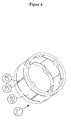
- FIG 4 is an oblique view of a shift ring with fold-out engagement elements in FIG shown relaxed state.
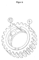
- a gear is shown in an oblique view with inwardly projecting teeth, in which engage the opened engagement elements according to FIG. 4 in the switched state. With their exposed faces, they embrace the teeth of the Gear.
- FIG. 7 shows a section through the device according to FIG. 1, the engagement elements are shown in a relaxed state.
- Fig. 8 shows the same section as Fig. 7, but with the pressurized state raised engaging elements.
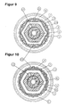
- FIG. 9 shows a variant of the engagement elements according to the section from FIG. 7.
- the engagement elements consist of resilient flat elements with bolt-like Surveys. In the relaxed state, these bolt-like elevations only reach up to maximum to the upper edge of the switching ring.
- FIG. 10 shows the variant of FIG. 9 in the pressurized state.
- the springy flat elements are pushed out through the oil-filled hose, whereby the bolt-like elevations in tooth-shaped recesses of the gear intervention.
- Fig. 11 are the possible variants of the positioning of the switching rings on the drive or the output shaft shown.
- the drive shaft of the gearbox is composed of a Gear shaft 1 with an attached shift ring 2, 2 'for each gear, one around Gear shaft 1 all around and exactly between gear shaft 1 and shift ring 2 arranged oil pressure hose 3, and one over the respective switching ring 2, 2 ' arranged gear 4 together.
- An oil distributor shaft lies within the transmission shaft 1 5 with a separate oil line 6 for each gear.
- the oil distributor shaft 5 is firmly connected to the gear housing 7, sh. Fig. 2.
- the Gear shaft 1 is rotatably supported in the gear housing 7 via the bearings 8.
- Of each Oil line 6 passes hydraulic oil through a connecting bore 12 and a connecting piece 9 in the associated oil pressure hose 3.
- this oil pressure will rise up in the associated oil pressure hose 3 and causes in the associated switching ring 2 that the fold-out engaging elements 10 set up and into the one above Engage gear 4 and take it with you.
- gear shaft 1 is shown separately in an oblique view.
- This gear shaft 1 is designed for a total of four courses.
- the oil pressure hoses are inserted in such a way that they Include gear shaft 1 adjacent and their oil-tight connectors 9 on the Connecting hole 12 the passage of the hydraulic oil from the oil line 6 and the Ensure distribution ring 14.
- the switching ring 2 is shown separately.
- the fold-out engagement elements 10 are shown here as tabs in the relaxed state. There are two tabs with theirs free end faces 15, 15 'directly opposite. By increasing the oil pressure in here Oil pressure hose 3, not shown below, the tabs to the outside pressed, with the free line surfaces 15, 15 'experiencing the greatest deflection.
- the present invention is expressly not limited to the embodiments shown here of the engaging elements 10, they only represent possible embodiments.
- the formwork ring 2 from FIG. 4 is shown activated in FIG. 5. It is important that the Engagement elements 10 on the outer edge of the end faces 5, 5 'beveled, preferred have curved surfaces 16, 16 '. Through these surfaces 16, 16 'the wear in reduced this area and the sliding intervention or release again in the internal toothing 17 of the gear 4 is facilitated.
- Fig. 6 the gear 4 is shown in an oblique view.
- the gear points to his Recesses on the inside which are suitable for the engagement elements of the switching ring 2 to record in the activated state, the unfolded engagement elements with their End faces include the inwardly projecting toothing 17 of the gear 4, whereby the Gear 4 is rotated.
- FIG. 7 shows a section through the device according to FIG. 1, the engagement elements are shown in the relaxed state, in one of the possible embodiments for the Engagement elements 10, which are shown here as liftable, resilient tabs.
- the Oil pressure hose 3 is not pressurized.
- the tabs 10 are in one plane with the Surface of the switching ring 2.
- the end faces 5, 5 'of the engagement elements 10 are mutually aligned in parallel.
- the internal toothing 17 of the gear 4 is exposed, that Gear 4 is not moved.
- Fig. 8 shows the same section as Fig. 7, but with raised engagement elements 10.
- Der Oil pressure hose 3 is pressurized.
- the tabs 10 are from the plane of the surface of the Switching ring 2 raised, the end faces 5, 5 'of the engaging elements 10 include form-fitting the internal toothing 17 of the gear 4, whereby the gear 4th is moved.
- FIG. 9 shows a variant of the engagement elements according to the section from FIG. 7.
- the engagement elements 10 consist of resilient flat elements 18 with bolt-like Surveys 19.
- the engagement elements 10 are not part of the switching ring 2 here, but are separate, exposed components, which between the switching ring 2 and the oil pressure hose 3 are arranged.
- the elevations 19 engage through recesses 20 in the switching ring, this reaching through the bolt-like elevations 19 only in the relaxed state reach a maximum of the upper edge of the switching ring.
- FIG. 10 shows the variant of FIG. 9 in the pressurized state.
- the Resilient flat elements 18 are through the oil-filled hose 3 to the outside pressed, whereby the bolt-like elevations 19 in tooth-shaped recesses 21 of the Engage gear 4.
- 11 shows the possible variants of the positioning of the switching rings on the drive or the output shaft shown. 11a, the shift rings are seated on the drive shaft, as is usually the case. 11b the shift rings sit on the output shaft. This arrangement can for the sake of Construction volume savings make sense to achieve a reduction in the gearbox.
- the particular advantages of this invention are that the synchronization is eliminated, which is why the shift forks, shift shafts, shift fingers, bearings and bearings, as well as the inner and outer switching actuation.
- the gearbox has one extremely short and narrow design and is therefore very space-saving. It lies as Two-shaft gearbox and has a significantly lower weight than conventional Transmission. In the case of an automatic transmission, in addition to the shift elements very complex and, above all, sluggishly functioning actuators.
- the Hydraulic control also enables individual and customized driving sensitive switching facial expressions.
Landscapes
- Engineering & Computer Science (AREA)
- General Engineering & Computer Science (AREA)
- Mechanical Engineering (AREA)
- Physics & Mathematics (AREA)
- Fluid Mechanics (AREA)
- Structure Of Transmissions (AREA)
- Gear-Shifting Mechanisms (AREA)
- Mechanical Operated Clutches (AREA)
Abstract
Description
Claims (17)
- Stufenschaltgetriebe, bestehend aus einem Getriebegehäuse, einer Antriebswelle mit einer Anzahl von Zahnrädern und einer Abtriebswelle mit einer Anzahl von korrespondierenden Zahnrädern, welche mit den Zahnrädern der Antriebswelle kämmend in Eingriff stehen, mindestens einer Getriebewelle, mehreren auf dieser Getriebewelle angeordneten Schaltringen mit radial wirkenden Eingriffselementen, welche in das zugeordnete Zahnrad eingreifen, um dieses zu drehen und über dieses Zahnrad ein damit korrespondierendes Zahnrad anzutreiben dadurch gekennzeichnet, dass mit dem Getriebegehäuse (7) mindestens eine Ölverteilerwelle (5) fix verbunden ist, dass die Ölverteilerwelle (5) innerhalb der Getriebewelle (1) angeordnet ist und für jede Gangstufe einen gesonderten Hydraulikölkanal (6) aufweist, welcher in einem Verteilerkanal 14 mündet, der zu einem Verbindungselement (9) führt, welcher das Übergangsstück für das Hydrauliköl zu einem ölgefüllten Schlauch (3) bildet, wobei der ölgefüllte Schlauch (3) auf der Getriebewelle (1) umlaufend unterhalb des Schaltringes (2) liegend angeordnet ist, dass der Schaltring (2) über anhebbare Eingriffselemente (10) verfügt, welche bei einer Druckbeaufschlagung des darunter liegenden Öldruckschlauches (3) mit Hydrauliköl aus einer entspannten Lage in eine nach Außen vorgerichtete Lage gebracht werden und dabei mit dem Zahnrad (4) in formschlüssige Wechselwirkung treten.
- Stufenschaltgetriebe nach Anspruch 1, dadurch gekennzeichnet, dass die Zahnräder (4), welche durch Eingriffselemente (10) eines Schaltringes (2) in Bewegung versetzt werden, auf einer Getriebewelle (1) positioniert sind, wobei diese Getriebewelle (1) sowohl auf der Antriebswelle als auch auf der Abtriebswelle, als auch auf beiden Wellen vorgesehen sein kann, wobei sie auch nur abschnittsweise vorgesehen sein kann.
- Stufenschaltgetriebe nach Anspruch 1 oder 2, dadurch gekennzeichnet, dass die Eingriffselemente (10) als federnde Laschen ausgebildet sind, welche aus der Wandung des Schaltringes 2 durch entsprechende Aufschlitzung entstehen und wobei je zwei unmittelbar nebeneinander liegende Laschen eine gemeinsame Mittelöffnung (11') bilden, welche eine nach innen weisende Verzahnung (17) des Zahnrades (4) aufnimmt, wobei die freiliegenden Stirnseiten (15, 15') der benachbarten Laschen diese Verzahnung (17) umgreifen und zwischen sich einklemmen.
- Stufenschaltgetriebe nach Anspruch 1 bis 3, dadurch gekennzeichnet, dass die Eingriffselemente (10) dergestalt ausgebildet sind, dass ihre größte Auslenkung in Laufrichtung des darüber liegenden Zahnrades 4 liegt.
- Stufenschaltgetriebe nach Anspruch 1 oder 2, dadurch gekennzeichnet, dass die Eingriffselemente (10) aus federnden flachen Elementen (18) mit bolzenartigen Elementen (19) gebildet werden, welche zwischen dem Schaltring (2) und dem ölgefüllten Schlauch (3) frei liegend angeordnet sind und bei Druckbeaufschlagung des ölgefüllten Schlauches (3) durch Ausnehmungen (20) des Schaltringes (2) durchgreifend in innenliegende Ausnehmungen (21) des Zahnrades (4) formschlüssig eingreifen.
- Stufenschaltgetriebe nach Anspruch 5, dadurch gekennzeichnet, dass die bolzenartigen Elemente (19) als Erhebungen der frei zwischen dem ölgefüllten Schlauch (3) und dem Schaltring (2) gelagerten, federnden Elemente (18) ausgebildet sind.
- Stufenschaltgetriebe nach Anspruch 5, dadurch gekennzeichnet, dass die bolzenartigen Elemente (19) als separate Bauteile auf den frei zwischen dem ölgefüllten Schlauch (3) und dem Schaltring (2) gelagerten, federnden Elementen (18) fixiert sind.
- Stufenschaltgetriebe nach Anspruch 1 oder 2, dadurch gekennzeichnet, dass die Eingriffselemente (10) als Haken ausgebildet sind, welche in innenliegende Ausnehmungen des Zahnrades (4) eingreifen.
- Verfahren zum Betreiben eines Stufenschaltgetriebes, insbesondere für Kraftfahrzeuge, dadurch gekennzeichnet, dass die Betätigung von Eingriffselementen (10), welche an einem Schaltring (2) angeordnet sind und mit einem Zahnrad (4) in formschlüssige Wechselwirkung treten, um dieses anzutreiben, über einen elastischen ölgefüllten Schlauch (3) erfolgt, welcher durch Druckbeaufschlagung mit Hydrauliköl gedehnt wird.
- Verfahren nach Anspruch 9, dadurch gekennzeichnet, dass bei einer Druckentspannung im Öldruckschlauch (3) das Zahnrad (4) die anhebbaren federnden Eingriffselemente (10) am Schaltring (2) in die entspannte Lage drücken und damit gleichzeitig das Hydrauliköl in den Hydrauliktank zurück drücken.
- Verfahren nach Anspruch 9, dadurch gekennzeichnet, dass bei einer Druckentspannung im Öldruckschlauch (3) ein bolzenartiges Element (19) durch die Federwirkung eines flachen Elementes (18) die formschlüssige Verbindung zum Zahnrad (4) verliert.
- Verfahren nach Anspruch 9, dadurch gekennzeichnet, dass das bolzenartige Element (19) durch Anlegen eines Unterdruckes auf den ölgefüllten Schlauch (3) die formschlüssige Verbindung zum Zahnrad (4) verliert.
- Verfahren nach einem der Ansprüche 9 bis 12, dadurch gekennzeichnet, dass die Druckentspannung im ölgefüllten Schlauch (3) durch Deaktivierung der Fahrkupplung und die Druckbeaufschlagung des ölgefüllten Schlauches (3) eines benachbarten Ganges durch neuerliche Aktivierung der Fahrkupplung ausgelöst wird.
- Verfahren nach einem der Ansprüche 9 bis 13, dadurch gekennzeichnet, dass die Wahl des Ölkanals (6) für die Druckbeaufschlagung des ölgefüllten Schlauches (3) über einen Schalthebel erfolgt.
- Verfahren nach einem der Ansprüche 9 bis 14, dadurch gekennzeichnet, dass die Wahl des Ölkanals (6) für die Druckbeaufschlagung des ölgefüllten Schlauches (3) über ein Signal erfolgt.
- Verfahren nach einem der Ansprüche 9 bis 15, dadurch gekennzeichnet, dass die Wahl des Ölkanals (6) für die Druckbeaufschlagung des ölgefüllten Schlauches (3) über ein Signal nach einem vorgegebenen Programm erfolgt.
- Verfahren nach einem der Ansprüche 9 bis 16, dadurch gekennzeichnet, dass die Druckbeaufschlagung eines bestimmten Ölkanals (6) annähernd gleichzeitig die Druckentlastung aller übrigen Kanäle (6) auslöst.
Applications Claiming Priority (2)
| Application Number | Priority Date | Filing Date | Title |
|---|---|---|---|
| AT0047801U AT5145U1 (de) | 2001-06-15 | 2001-06-15 | Stufenschaltgetriebe, insbesondere für kraftfahrzeuge |
| AT4782001 | 2001-06-15 |
Publications (2)
| Publication Number | Publication Date |
|---|---|
| EP1422450A2 true EP1422450A2 (de) | 2004-05-26 |
| EP1422450A3 EP1422450A3 (de) | 2005-03-16 |
Family
ID=3491673
Family Applications (1)
| Application Number | Title | Priority Date | Filing Date |
|---|---|---|---|
| EP02008470A Withdrawn EP1422450A3 (de) | 2001-06-15 | 2002-04-15 | Hydraulische, radial wirkende Kupplungselemente für Stufenschaltgetriebe |
Country Status (2)
| Country | Link |
|---|---|
| EP (1) | EP1422450A3 (de) |
| AT (1) | AT5145U1 (de) |
Cited By (4)
| Publication number | Priority date | Publication date | Assignee | Title |
|---|---|---|---|---|
| DE102007007369A1 (de) * | 2007-02-14 | 2008-08-21 | Schaeffler Kg | Synchronisiereinrichtung für ein Schaltgetriebe |
| EP2096335A1 (de) * | 2008-02-27 | 2009-09-02 | HOERBIGER Synchron Technik GmbH & Co. KG | Getriebe |
| DE102012012003A1 (de) | 2012-06-16 | 2013-12-19 | Daimler Ag | Getriebewelle mit zumindest einem Schmiermittelkanal und Verfahren zur Herstellung einer Getriebewelle |
| CN115823246A (zh) * | 2022-11-21 | 2023-03-21 | 合肥工业大学 | 一种用于拖拉机变速器机械挂档的修正系统与方法 |
Families Citing this family (1)
| Publication number | Priority date | Publication date | Assignee | Title |
|---|---|---|---|---|
| DE20314476U1 (de) * | 2003-09-18 | 2004-04-01 | Jegel, Franz Peter, Ing. | Gangstufenschaltgetriebe mit Klauenschaltung |
Family Cites Families (7)
| Publication number | Priority date | Publication date | Assignee | Title |
|---|---|---|---|---|
| US3663027A (en) * | 1970-09-14 | 1972-05-16 | Ingersoll Milling Machine Co | Fluid actuated clamp |
| DE3805710A1 (de) * | 1988-02-24 | 1989-09-07 | Achenbach Buschhuetten Gmbh | Schaltgetriebe |
| JPH0251663A (ja) * | 1988-08-11 | 1990-02-21 | Honda Motor Co Ltd | 車両用油圧変速機 |
| SE503936C2 (sv) * | 1995-02-01 | 1996-09-30 | Etp Transmission Ab | Hydraulisk spännbussning med sigmaformade gavlar |
| DE19512642A1 (de) * | 1995-04-05 | 1996-10-10 | Bayerische Motoren Werke Ag | Schaltgetriebe |
| GB9817789D0 (en) * | 1998-08-15 | 1998-10-14 | Clarke Leslie J | Hydrualic pressure operated lock-up mechanism |
| GB9918642D0 (en) * | 1999-08-06 | 1999-10-13 | Ricardo Mtc Limited | Gearboxes |
-
2001
- 2001-06-15 AT AT0047801U patent/AT5145U1/de not_active IP Right Cessation
-
2002
- 2002-04-15 EP EP02008470A patent/EP1422450A3/de not_active Withdrawn
Non-Patent Citations (1)
| Title |
|---|
| None |
Cited By (5)
| Publication number | Priority date | Publication date | Assignee | Title |
|---|---|---|---|---|
| DE102007007369A1 (de) * | 2007-02-14 | 2008-08-21 | Schaeffler Kg | Synchronisiereinrichtung für ein Schaltgetriebe |
| EP2096335A1 (de) * | 2008-02-27 | 2009-09-02 | HOERBIGER Synchron Technik GmbH & Co. KG | Getriebe |
| DE102012012003A1 (de) | 2012-06-16 | 2013-12-19 | Daimler Ag | Getriebewelle mit zumindest einem Schmiermittelkanal und Verfahren zur Herstellung einer Getriebewelle |
| CN115823246A (zh) * | 2022-11-21 | 2023-03-21 | 合肥工业大学 | 一种用于拖拉机变速器机械挂档的修正系统与方法 |
| CN115823246B (zh) * | 2022-11-21 | 2024-06-11 | 合肥工业大学 | 一种用于拖拉机变速器机械挂档的修正方法 |
Also Published As
| Publication number | Publication date |
|---|---|
| EP1422450A3 (de) | 2005-03-16 |
| AT5145U1 (de) | 2002-03-25 |
Similar Documents
| Publication | Publication Date | Title |
|---|---|---|
| EP2580497B1 (de) | Betätigungsvorrichtung für ein schaltgetriebe | |
| DE112013005139B4 (de) | Betätigungsvorrichtung und Getriebe | |
| DE3240518A1 (de) | Schalteinrichtung | |
| DE3150885C2 (de) | ||
| DE2930950C2 (de) | Fahrzeugwechselgetriebe, insbesondere für Ackerschlepper | |
| DE102005018899A1 (de) | Rastelement | |
| DE60219107T2 (de) | Schaltsystem für manuelles Getriebe | |
| EP0770802B1 (de) | Schalteinrichtung für Kraftfahrzeug-Wechselgetriebe mit Abbremsung der Eingangswelle beim Einschalten des Rückwärtsganges | |
| EP3339682A1 (de) | Schieberad für eine schaltgetriebeanordnung | |
| EP1422450A2 (de) | Hydraulische, radial wirkende Kupplungselemente für Stufenschaltgetriebe | |
| DE69614329T2 (de) | Bolzen-typ Synchronisiereinheit | |
| DE3928816C2 (de) | ||
| DE102018206392B4 (de) | Schalteinrichtung zur durchführung von gangwechseln in einem fahrzeuggetriebe | |
| DE10045266A1 (de) | Schaltvorrichtung zum Betätigen eines mehrstufigen Schaltgetriebes | |
| DE2813099A1 (de) | Doppel-h-schaltung fuer ein vielganggetriebe | |
| DE102004051421A1 (de) | Vorrichtung zum Schalten zweier Gangräder mittels einer aus einer neutralen Stellung in Richtung der Gangräder verschiebbaren Schiebemuffe | |
| DE202004006953U1 (de) | Schalteinrichtung für ein Wechselgetriebe mit vereinfachter Schaltkulisse | |
| DE20110302U1 (de) | Stufenschaltgetriebe, insbesondere für Kraftfahrzeuge | |
| EP1517071B1 (de) | Klauenschaltung | |
| DE3446357A1 (de) | Anordnung zum anbringen einer zahnrad-schalteinrichtung in einem getriebe | |
| DE10021176B4 (de) | Automatisiertes Schaltgetriebe für ein Kraftfahrzeug | |
| DE10352962A1 (de) | Gangschaltmechanismus | |
| DE102005028803A1 (de) | Synchronisierungseinrichtung für ein Schaltgetriebe | |
| DE102005011274A1 (de) | Schaltvorrichtung für ein Getriebe eines Kraftfahrzeugs | |
| DE10155519B4 (de) | Schaltvorrichtung für ein Wechselgetriebe |
Legal Events
| Date | Code | Title | Description |
|---|---|---|---|
| PUAI | Public reference made under article 153(3) epc to a published international application that has entered the european phase |
Free format text: ORIGINAL CODE: 0009012 |
|
| AK | Designated contracting states |
Kind code of ref document: A2 Designated state(s): AT BE CH CY DE DK ES FI FR GB GR IE IT LI LU MC NL PT SE TR |
|
| AX | Request for extension of the european patent |
Extension state: AL LT LV MK RO SI |
|
| PUAL | Search report despatched |
Free format text: ORIGINAL CODE: 0009013 |
|
| AK | Designated contracting states |
Kind code of ref document: A3 Designated state(s): AT BE CH CY DE DK ES FI FR GB GR IE IT LI LU MC NL PT SE TR |
|
| AX | Request for extension of the european patent |
Extension state: AL LT LV MK RO SI |
|
| AKX | Designation fees paid | ||
| REG | Reference to a national code |
Ref country code: DE Ref legal event code: 8566 |
|
| STAA | Information on the status of an ep patent application or granted ep patent |
Free format text: STATUS: THE APPLICATION IS DEEMED TO BE WITHDRAWN |
|
| 18D | Application deemed to be withdrawn |
Effective date: 20050917 |