EP1422675A1 - Vorrichtung zur Entkopplung von staubbelasteten Anlagen mit Explosionsgefahr - Google Patents
Vorrichtung zur Entkopplung von staubbelasteten Anlagen mit Explosionsgefahr Download PDFInfo
- Publication number
- EP1422675A1 EP1422675A1 EP03010529A EP03010529A EP1422675A1 EP 1422675 A1 EP1422675 A1 EP 1422675A1 EP 03010529 A EP03010529 A EP 03010529A EP 03010529 A EP03010529 A EP 03010529A EP 1422675 A1 EP1422675 A1 EP 1422675A1
- Authority
- EP
- European Patent Office
- Prior art keywords
- decoupling
- explosion
- dust
- risk
- window
- Prior art date
- Legal status (The legal status is an assumption and is not a legal conclusion. Google has not performed a legal analysis and makes no representation as to the accuracy of the status listed.)
- Granted
Links
Images


Classifications
-
- G—PHYSICS
- G08—SIGNALLING
- G08B—SIGNALLING SYSTEMS, e.g. PERSONAL CALLING SYSTEMS; ORDER TELEGRAPHS; ALARM SYSTEMS
- G08B17/00—Fire alarms; Alarms responsive to explosion
- G08B17/12—Actuation by presence of radiation or particles, e.g. of infrared radiation or of ions
-
- A—HUMAN NECESSITIES
- A62—LIFE-SAVING; FIRE-FIGHTING
- A62C—FIRE-FIGHTING
- A62C3/00—Fire prevention, containment or extinguishing specially adapted for particular objects or places
- A62C3/04—Fire prevention, containment or extinguishing specially adapted for particular objects or places for dust or loosely-baled or loosely-piled materials, e.g. in silos, in chimneys
Definitions
- the invention relates to a device for decoupling dust-laden systems with a risk of explosion, preferably zone 20 according to ATEX compared to a zone with less or no risk of explosion according to the preamble of the first claim.
- the invention can be used wherever moving dust-like particles are present and there is a risk of explosion, and observation of these spaces is required from an area with little or no risk of explosion.
- An explosion hazard according to ATEX 20 should preferably be understood as an explosion hazard.
- the dust-like particles can be dust particles in pipes, transport devices or cyclones in the chipboard industry, the textile industry, the chemical industry, the metal processing industry (recycling and milling industry), for example in the crushing and suction of magnesium particles, in furniture manufacture, in the Wood-shaped particles are suctioned off or coal particles in aggregates of the brownstone or anthracite coal processing industry or in the pneumatic conveying of black powder.
- the decoupling device can be used for spark extinguishing systems for moving dust-like particles in systems with an increased risk of explosion.
- the device can also be used for flame monitoring, flow rate and temperature monitoring in potentially explosive areas. If the condition of the dust-prone area must be observed in hazardous areas, there is a requirement that all units and devices in the potentially explosive area have the required safety approval for the potentially explosive area.
- a sensor for monitoring the condition in an area with an explosion hazard according to ATEX 21 cannot be used in an area with the explosion level according to ATEX 20. Sensors for sparks, fire detection, temperature, flow or flow measurement should be meant.
- processing machines with pneumatic suction and conveying devices such as those found in the woodworking industry and in the textile, recycling, food, animal feed, leather, rubber and chemical industries, pose particular fire risks Precautions are required. Sparks caused by processing machines and contaminants, such as metal parts and stones in the conveyor systems, reach the following systems via the conveyor lines: Example: in the fabric filter or in the silo. Here they can cause smoldering fires, which develop unnoticed when covered by the following material. Large enough fires or dust explosions are often the result. To prevent this, spark extinguishing systems have been developed. These spark extinguishing systems are usually sensors that are coupled to an extinguishing center.
- the fire detection sensors which are referred to as spark detectors, are inserted through a hole, for example in a pipeline. If there are glowing sparks in the flow of the pipe, these are recognized, trigger an electrical signal to the fire alarm control panel, after which an extinguishing unit in the pipe is activated, which is further downstream in the direction of flow of the particles in the system and for extinguishing the particles in the delivery pipe provides.
- DE 40 26 041 C2 discloses a device for detecting sparks in a flowed-through room, wherein at least one optical waveguide opens into the room with a first end, a second end of each optical waveguide being opposite a photoreceiver which generates electrical signals when sparks occur receives.
- the solution according to the invention provides a device for decoupling dust-laden systems with a risk of explosion, preferably zone 20 according to ATEX over a zone with little or no risk of explosion in such a way that a decoupling window is arranged in the wall of the system, with one side of the decoupling window, the moving particles are located in the potentially explosive area, which has a different and generally higher explosion level and a sensor system, for example fire detection, is arranged on the other side of the decoupling window.
- a registration device for example a fire alarm detection, which is coupled to a fire alarm center, to which an extinguishing device is arranged which triggers the extinguishing in the relevant unit.
- An application of the device according to the invention provides z.
- the decoupling window can, for example, be arranged in a pipe, inside which there is an increased explosion level, while there is no safety-relevant space outside the decoupling window and the pipe. This means that the fire detection facilities in connection with the fire alarm center do not have to meet any special security level requirements, which leads to cost savings.
- the decoupling window can be arranged either on round or square pipes made of metal or steel or other materials or directly in a silo or collecting container. It is advantageous to arrange the decoupling window on both sides of a tube. It must be connected to the walls of the pipe to be impermeable to gas and pressure. It is advantageous to arrange the decoupling window on both sides of the measuring points.
- the decoupling window is advantageous to design as a ring running around the conveyor tube. If there is an inspection flap in the pipes, the decoupling window can be incorporated instead of the inspection flap.
- the decoupling window should be located in the pipeline or system so that it is located after a location where there is a fire potential and before the location where there is an explosion potential.
- the spark extinguishing system has a decoupling window in the direction of movement of the particles, which is arranged after the extinguishing unit. This can be used to determine whether the deletion is intensive enough and if necessary a more intensive deletion can be carried out. This arrangement represents a further improvement in safety in potentially explosive systems of the type mentioned.
- the fire detection device can be sensors that detect the entire area of the photon spectrum.
- the fire detection can consist of a transmitter and a receiver.
- the decoupling window must be suitable for allowing the appropriate radiation from the sensor (receiver) or the transmitter to pass through. Glass, plastic, calcium fluoride or other known and comparable substances can be used for this. With the decoupling window, it is not only possible to sense and detect ignition or fire potential in potentially explosive areas, but also to observe changes in state and measure the speed of faults.
- Optical sensors are used as sensors and for function monitoring and control Receiver arranged. Level, monitoring, temperature, gas, density, Dimension and color detection.
- FIG. 1 shows a pipe with pipe walls 1 made of steel, into which decoupling windows 4 were inserted on both sides, which are impermeable to gas and pressure, so that the system inside the pipe walls 1 is independent of the system which is located outside the pipe wall 1.
- a pneumatic transport of quickly inflammable particles 2, 3 takes place within the tube wall 1. These are dusts 3 which form an explosion potential in collecting containers 1, so that an ignition potential 2 must be extinguished before a storage container is reached. This presupposes that the inflammation potential 2 is recognized beforehand. Spark detectors or detection devices 5 that are not approved for the potentially explosive atmosphere inside the pipe wall 1 are to be used.
- the corresponding spark detectors 5 are arranged behind the decoupling window 4, which consist of a sensor and a pane and which are connected to a fire alarm control panel 6 by means of lines.
- the decoupling window 4 consists of a plastic that can be determined by infrared rays.
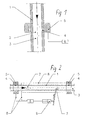
- FIG. 2 shows a conveyor system in which decoupling windows 4, which are all-round, were let into the tube walls 1 of a steel tube at two points. Spark detectors 5 are arranged on both sides of the decoupling window 4, one line 8 leading to the fire alarm control panel 6.
- the first spark detector 5 detects an ignition potential 2 in the tube
- a signal is sent to the fire alarm center 6 which triggers the fire extinguishing device 9, an extinguishing agent being sprayed into the tube via a nozzle 7. This happens at the point in time at which the ignition potential 2 passes through this pipe section.
- Another spark detector 5 makes it possible to check whether the ignition potential 2 has been completely extinguished or whether the extinguishing process is to be intensified or measures have to be taken on the collecting container.
- Figure 3 shows a silo or a cyclone, which is flowed from below, immediately after the inlet decoupling window 4 are arranged with spark detectors with a Fire control panel 6 are coupled. If there is an ignition potential 2 in the glow current an extinguishing system can be triggered at a suitable point.
- FIG. 4 shows a tube wall 1 into which a decoupling window 4 rotates in shape a ring is arranged, on both sides of which fire detection devices 5 are arranged, one infrared transmitter 11 on one side and one on the other side Infrared receiver is arranged, the infrared receiver 12 with the fire control panel 6 is coupled.
- FIG. 5 shows a pipe in the pipe wall 1 instead of an inspection flap Decoupling window 4 was arranged pressure and gas-tight, with behind the Revision window is a spark detector 5, the explosion-free dust 3, the pneumatically conveyed, checked for inflammation potential 2.
- the proposed system succeeds in fire detection elements or spark detectors for use potentially explosive rooms without meeting the requirements must be placed on the fire detection units in these rooms. Farther it is possible to control to what extent deletion processes after the detection of Inflammation potential was carried out intensely enough.
Landscapes
- Business, Economics & Management (AREA)
- Emergency Management (AREA)
- Health & Medical Sciences (AREA)
- Public Health (AREA)
- Physics & Mathematics (AREA)
- General Physics & Mathematics (AREA)
- Fire-Extinguishing By Fire Departments, And Fire-Extinguishing Equipment And Control Thereof (AREA)
- Fire Alarms (AREA)
Abstract
Description
Die Erfindung ist überall dort anwendbar, wo bewegte staubförmige Partikel vorhanden sind und Explosionsgefahr besteht und aus einem Bereich mit geringer Explosionsgefahr oder ohne Explosionsgefahr ein Beobachten dieser Räume erforderlich ist. Als Explosionsgefahr soll vorzugsweise eine Explosionsgefahr nach ATEX 20 zu verstehen sein. Bei den staubförmigen Partikeln kann es sich handeln um Staubteilchen in Rohren, Transporteinrichtungen oder Zyklonen der Spanplattenindustrie, der Textilindustrie, der chemischen Industrie, der metallverarbeitenden Industrie (Recycling- und Mühlenindustrie), beispielsweise beim Zerkleinern und Absaugen von Magnesiumteilchen, bei der Möbelfabrikation, bei der holzförmige Teilchen abgesaugt werden oder aber Kohleteilchen bei Aggregaten der braunstein- oder anthrazitkohleverarbeitenden Industrie oder bei der pneumatischen Förderung von Schwarzpulver.
Sofern in staubbelasteten Bereichen explosionsgefährdete Anlagen der Zustand des staubgefährdeten Bereichs beobachtet werden muß, besteht die Forderung, alle Aggregate und Vorrichtungen im explosionsgefährdeten Bereich die für den explosionsgefährdeten Bereich erforderliche Sicherheitszulassung aufweist. Ein Sensor zur Zustandsbeobachtung in einem Bereich mit einer Explosionsgefahr nach ATEX 21 kann so nicht in einem Bereich angewendet werden, der die Explosionsstufe nach ATEX 20 aufweist. Als Sensor sollten Sensoren zur Funken-, Branderkennung, Temperatur, Fließ- oder Strömungsmessung gemeint sein.
Aus DE 40 26 041 C2 geht eine Vorrichtung zum Erkennen von Funken in einem durchströmten Raum hervor, wobei in den Raum wenigstens ein Lichtwellenleiter mit einem ersten Ende mündet, wobei ein zweites Ende jedes Lichtwellenleiters einem Photoempfänger gegenüberliegt, der beim Auftreten von Funken entsprechend elektrische Signale empfängt.
Es ist daher Aufgabe der Erfindung, eine Vorrichtung zu entwickeln, mit der es möglich ist, elektrische Betriebsmittel zur Erkennung Zustandsänderung, insbesondere von Zündpotentialen in elektrisch gefährdeten Räumen einzusetzen, ohne daß das elektrische Betriebsmittel eine Zulassung für diese Räume aufweist. Weiterhin soll gewährleistet sein, ein bewegtes Zündinitial in den explosionsgefährdeten Bereich gelangt, bevor es den Transportbereich verlässt und zuverlässig gelöscht wird.
Diese Aufgabe wird durch eine Vorrichtung nach den kennzeichnenden Merkmalen des ersten Patentanspruches gelöst. Unteransprüche geben vorteilhafte Ausgestaltungen der Erfindung wieder.
Die erfindungsgemäße Lösung sieht eine Vorrichtung zur Entkopplung von staubbelasteten Anlagen mit Explosionsgefahr, vorzugsweise der Zone 20 nach ATEX gegenüber einer Zone mit geringer oder keiner Explosionsgefahr in der Weise vor, daß ein Entkopplungsfenster in der Wand der Anlage angeordnet ist, wobei sich auf der einen Seite des Entkopplungsfensters die bewegenden Partikel im explosionsgefährdeten Raum befinden, der eine andere und in der Regel höhere Explosionsstufe aufweist und auf der anderen Seite des Entkopplungsfensters eine Sensorik, beispielsweise eine Branderkennung, angeordnet ist. Diese ist in bekannterweise mit einer Registriereinrichtung, beispielsweise einer Brandmeldeerkennung, verbunden, die mit einer Brandmeldezentrale gekoppelt ist, zu der eine Löschvorrichtung angeordnet ist, die das Löschen im betreffenden Aggregat auslöst. Eine Anwendung der erfindungsgemäßen Vorrichtung stellt z. B. eine Funkenlöschanlage für staubförmige Partikel in Anlagen mit erhöhtem Explosionsschutz dar. Das Entkopplungsfenster kann beispielsweise in einem Rohr angeordnet sein, in dessen Inneren eine erhöhte Explosionsstufe herrscht, während sich außerhalb des Entkopplungsfensters und des Rohres kein sicherheitsrelevanter Raum befindet. Damit müssen die Einrichtungen zur Branderkennung im Zusammenhang mit der Brandmeldezentrale keine besonderen Anforderungen an die Sicherheitsstufe aufweisen, was zu Kostenersparnissen führt. Das Entkopplungsfenster kann sowohl an runden als auch an eckigen Rohren aus Metall oder Stahl oder anderen Materialien oder unmittelbar in einem Silo oder Sammelbehälter angeordnet sein. Vorteilhaft ist es, das Entkopplungsfenster beidseitig eines Rohres anzuordnen. Es muss mit den Wandungen des Rohres gas- und druckundurchlässig verbunden sein. Vorteilhaft ist es, das Entkopplungsfenster beidseitig der Messstellen anzuordnen. Weiterhin ist es vorteilhaft, das Entkopplungsfenster als einen um das Förderrohr umlaufenden Ring auszubilden.
Sollte eine Revisionsklappe in den Rohrleitungen vorhanden sein, so kann das Entkopplungsfenster anstelle der Revisionsklappe eingearbeitet werden.
Das Entkopplungsfenster sollte in der Rohrleitung oder der Anlage so angeordnet sein, daß es nach einem Ort angeordnet ist, in dem ein Brandpotential entsteht und vor dem Ort, in dem ein Explosionspotential vorhanden ist.
Vorteilhaft ist weiterhin, daß die Funkenlöschanlage ein Entkopplungsfenster in Bewegungsrichtung der Partikel aufweist, welches nach dem Löschaggregat angeordnet ist. Damit kann erkannt werden, ob das Löschen intensiv genug ist und bei Bedarf eine intensivere Löschung durchgeführt werden. Deise Anordnung stellt eine weitere Verbesserung zur Sicherheit in explosionsgefährdeten Anlagen der genannten Art dar.
Bei der Branderkennungseinrichtung kann es sich um Sensoren handeln, die den gesamten Bereich des Photonenspektrums detektieren.
Die Branderkennung kann aus einem Sender und einem Empfänger bestehen.
Das Entkopplungsfenster muss geeignet sein, die entsprechende Strahlung des Sensors (Empfänger) oder des Senders gut durchzulassen. Dafür sind Glas, Kunststoff, Calciumfluorid oder dem Fachmann andere bekannte und vergleichbare Stoffe einsetzbar. Mit dem Entkopplungsfenster ist es nicht nur möglich, Zünd- oder Brandpotentialein explosionsgefährdeten Bereichen zu sensieren und zu erkennen, sondern auch Zustandsänderungen zu beobachten und Geschwindigkeiten von Störungen zu messen.
- Figur 1:
- Entkopplungsfenster in der Wandung eines Rohres mit Branderkennungsaggregaten am Fenster
- Figur 2:
- Fördersystem mit der erfindungsgemäßen Branderkennungseinrichtung, Brandmeldezentrale und Funkenlöschanlage an einem Stahlrohr
- Figur 3:
- erfindungsgemäßes Entkopplungsfenster mit Branderkennungsaggregaten an einem Silo
- Figur 4:
- Fördersystem mit umlaufendem Entkopplungsfenster an einem Metallrohr
- Figur 5:
- Entkopplungsfenster in einem Metallrohr anstelle einer Revisionsklappe
Die Figur 2 zeigt ein Fördersystem, bei dem in die Rohrwandungen 1 eines Stahlrohres Entkopplungsfenster 4 , die umlaufend sind, an zwei Stellen eingelassen wurden. Beidseitig der Entkopplungsfenster 4 sind Funkenmelder 5 angeordnet, von denen eine Leitung 8 zur Brandmeldezentrale 6 führt. Für den Fall, daß der erste Funkenmelder 5 ein Entzündungspotential 2 im Rohr erkennt, ergeht ein Signal an die Brandmeldezentrale 6, die die Feuerlöscheinrichtung 9 auslöst, wobei über eine Düse 7 ein Löschmittel in das Rohr versprüht wird. Das geschieht zu dem Zeitpunkt, an dem das Entzündungspotential 2 diesen Rohrabschnitt passiert. Durch einen weiteren Funkenmelder 5 besteht die Möglichkeit zu prüfen, ob das Entzündungspotential 2 vollständig gelöscht wurde oder ob der Löschvorgang zu intensivieren ist oder Maßnahmen am Sammelbehälter getroffen werden müssen.
- 1
- Rohrwandung
- 2
- Entzündungspotential
- 3
- Staub im explosionsgefährdeten Raum
- 4
- Entkopplungsfenster
- 5
- Branderkennung, Funkenmelder, Sensor
- 6
- Brandmeldezentrale
- 7
- Löschdüse, Löschaggregat
- 8
- Leitung zur Brandmeldezentrale
- 9
- Feuerlöscheinrichtung
- 10
- Silowandung
- 11
- Infrarotsender
- 12
- Infrarotempfänger
- 13
- Glasschicht
Claims (9)
- Vorrichtung zur Entkopplung von staubbelasteten Anlagen mit Explosionsgefahr, vorzugsweise der Zone 20 nach ATEX gegenüber eine Zone mit geringer oder ohne Explosionsgefahr, bestehend aus einer Förderanlage mit einer Wandung, hinter der sich die staubförmigen Partikel in einem Luftstrom bewegen und einem Sensor zur meßtechnischen Erfassung mit einer Meldeelektronik, gekennzeichnet durchein Entkopplungsfenster (4) in der Wand (1) der Anlage, auf dessen einer Seite sich die bewegten Partikel (2, 3) im explosionsgefährdeten Raum befinden und auf dessen anderer Seite ein Sensor (5) zum Erkennen von Veränderungen im explosionsgefährdeten Raum, verbunden mit einer Auswerteelektronik (6) und Löscheinheiten (7,9) angeordnet ist.
- Vorrichtung nach Anspruch 1, dadurch gekennzeichnet, daß das Entkopplungsfenster (4) nach einem Ort angeordnet ist, in dem Brände und Funken entstehen können und vor Räumen, in denen ein Explosionspotential vorhanden ist.
- Vorrichtung nach Anspruch 1, gekennzeichnet durch ein Entkopplungsfenster (4) in Bewegungsrichtung der Partikel (2, 3) vor einem Löschaggregat (7).
- Vorrichtung nach den Ansprüchen 1 bis 3, dadurch gekennzeichnet, daß das Entkopplungsfenster (4) gas- und druckdicht angeordnet ist.
- Vorrichtung nach den Ansprüchen 1 bis 4, dadurch gekennzeichnet, daß das Entkopplungsfenster (4) aus Glas, Kunststoff oder Kaliumfluorid oder einem vergleichbaren Werkstoff besteht.
- Vorrichtung nach den Ansprüchen 1 bis 5, dadurch gekennzeichnet, daß das Entkopplungsfenster (4) beidseitig des Beobachtungsortes angeordnet ist.
- Vorrichtung nach den Ansprüchen 1 bis 6, dadurch gekennzeichnet, daß zur Branderkennung (5) Sensoren im Infrarot- ,UV- oder im sichtbaren Bereich angeordnet sind.
- Vorrichtung nach den Ansprüchen 1 bis 7, dadurch gekennzeichnet, daß zur Branderkennung (5) Funken- oder Flammenmelder bestehend aus Sender (11) und Empfänger (12) angeordnet sind.
- Vorrichtung nach den Ansprüchen 1 bis 8, dadurch gekennzeichnet, daß zur Funktionsüberwachung- und Steuerung optische Sensoren als Sensor und Empfänger angeordnet sind, wie z. B. Füllstands-, Überwachungs-, Temperatur-, Gas-, Dichte-, Dimensions- und Farberkennung.
Applications Claiming Priority (2)
| Application Number | Priority Date | Filing Date | Title |
|---|---|---|---|
| DE20218136U DE20218136U1 (de) | 2002-11-21 | 2002-11-21 | Funkenlöschanlage für bewegte staubförmige Partikel |
| DE20218136U | 2002-11-22 |
Publications (2)
| Publication Number | Publication Date |
|---|---|
| EP1422675A1 true EP1422675A1 (de) | 2004-05-26 |
| EP1422675B1 EP1422675B1 (de) | 2012-06-27 |
Family
ID=7977250
Family Applications (1)
| Application Number | Title | Priority Date | Filing Date |
|---|---|---|---|
| EP20030010529 Expired - Lifetime EP1422675B1 (de) | 2002-11-21 | 2003-05-10 | Vorrichtung zur Entkopplung von staubbelasteten Anlagen mit Explosionsgefahr |
Country Status (2)
| Country | Link |
|---|---|
| EP (1) | EP1422675B1 (de) |
| DE (1) | DE20218136U1 (de) |
Cited By (3)
| Publication number | Priority date | Publication date | Assignee | Title |
|---|---|---|---|---|
| DE102006001208A1 (de) * | 2006-01-10 | 2007-07-19 | Fagus-Grecon Greten Gmbh & Co Kg | Vorrichtung zum Löschen von glühenden Feststoffteilchen |
| EP2244237A1 (de) | 2009-04-21 | 2010-10-27 | Minimax GmbH & Co. KG | Vorrichtung zum Erkennen und Melden von Feuererscheinungen mit brennbaren Materialen |
| CN114306978A (zh) * | 2022-01-07 | 2022-04-12 | 朱龙辉 | 一种港口谷仓防尘爆炸后灭火报警装置 |
Families Citing this family (5)
| Publication number | Priority date | Publication date | Assignee | Title |
|---|---|---|---|---|
| DE102009017858B4 (de) * | 2009-03-25 | 2016-05-12 | Oliver Frieters | Filtersteuerung mit Reststaubgehaltanzeige sowie Steuerungsverfahren hierfür |
| DE102009017859B4 (de) * | 2009-03-25 | 2016-05-12 | Oliver Frieters | Entstaubungsanlage mit Funkeinschaltsteuerung und Verfahren zum Anschließen der Entstaubungsanlage |
| DE102012014143A1 (de) * | 2012-07-18 | 2014-01-23 | Man Diesel & Turbo Se | Gasführendes Svstem und damit ausgerüstete Brennkraftmaschine |
| DE102012017534B4 (de) | 2012-09-05 | 2014-11-06 | Entstaubungsgeräte Pulsnitz GmbH | Absaugvorrichtung |
| DE202012008456U1 (de) | 2012-09-05 | 2012-09-28 | Entstaubungsgeräte Pulsnitz GmbH | Absaugvorrichtung |
Citations (7)
| Publication number | Priority date | Publication date | Assignee | Title |
|---|---|---|---|---|
| DE7533568U (de) * | 1975-10-22 | 1976-02-19 | Grecon Greten Consulting Gmbh & Co, 3220 Alfeld | Meßvorrichtung eines Feueranzeigegerätes |
| DE2916086A1 (de) | 1979-04-20 | 1980-10-23 | Preussag Ag Feuerschutz | Einrichtung zum melden von optischen feuererscheinungen, insbesondere funken |
| US4855118A (en) | 1987-04-15 | 1989-08-08 | Nichia Kagaku Kogyo K.K. | Method of producing fluorapatite |
| US4855718A (en) * | 1987-07-28 | 1989-08-08 | Firetek Corporation | Fire detection system employing at least one optical waveguide |
| DE4036041A1 (de) | 1990-01-30 | 1991-08-01 | Grecon Greten Gmbh & Co Kg | Vorrichtung zur erkennung von funken in einem durchstroemten raum |
| DE19843841A1 (de) * | 1998-09-24 | 2000-04-20 | Anseros Klaus Nonnenmacher Gmb | Meßzelle für fotometrische Messungen |
| US6119785A (en) * | 1996-07-17 | 2000-09-19 | Fagus-Grecon Greten Bmbh & Co. Kg | Fire-extinguishing device and valve unit therefor |
Family Cites Families (3)
| Publication number | Priority date | Publication date | Assignee | Title |
|---|---|---|---|---|
| DE3017144C2 (de) | 1980-05-05 | 1984-09-27 | Preussag Ag Feuerschutz, 2060 Bad Oldesloe | Einrichtung zu Melden von optischen Feuererscheinungen, insbesondere Funken |
| DE3134499A1 (de) | 1981-09-01 | 1983-03-17 | Golovnoe konstruktorskoe bjuro derevoobrabatyvajuščego oborudovanija, Vologda | Verfahren zur verhinderung der entzuendung und explosion von schuettgut |
| DE19726096C1 (de) | 1997-06-19 | 1999-03-04 | Manfred Tolle | Verfahren und Vorrichtung zur Brandverhinderung |
-
2002
- 2002-11-21 DE DE20218136U patent/DE20218136U1/de not_active Expired - Lifetime
-
2003
- 2003-05-10 EP EP20030010529 patent/EP1422675B1/de not_active Expired - Lifetime
Patent Citations (7)
| Publication number | Priority date | Publication date | Assignee | Title |
|---|---|---|---|---|
| DE7533568U (de) * | 1975-10-22 | 1976-02-19 | Grecon Greten Consulting Gmbh & Co, 3220 Alfeld | Meßvorrichtung eines Feueranzeigegerätes |
| DE2916086A1 (de) | 1979-04-20 | 1980-10-23 | Preussag Ag Feuerschutz | Einrichtung zum melden von optischen feuererscheinungen, insbesondere funken |
| US4855118A (en) | 1987-04-15 | 1989-08-08 | Nichia Kagaku Kogyo K.K. | Method of producing fluorapatite |
| US4855718A (en) * | 1987-07-28 | 1989-08-08 | Firetek Corporation | Fire detection system employing at least one optical waveguide |
| DE4036041A1 (de) | 1990-01-30 | 1991-08-01 | Grecon Greten Gmbh & Co Kg | Vorrichtung zur erkennung von funken in einem durchstroemten raum |
| US6119785A (en) * | 1996-07-17 | 2000-09-19 | Fagus-Grecon Greten Bmbh & Co. Kg | Fire-extinguishing device and valve unit therefor |
| DE19843841A1 (de) * | 1998-09-24 | 2000-04-20 | Anseros Klaus Nonnenmacher Gmb | Meßzelle für fotometrische Messungen |
Cited By (5)
| Publication number | Priority date | Publication date | Assignee | Title |
|---|---|---|---|---|
| DE102006001208A1 (de) * | 2006-01-10 | 2007-07-19 | Fagus-Grecon Greten Gmbh & Co Kg | Vorrichtung zum Löschen von glühenden Feststoffteilchen |
| DE102006001208B4 (de) * | 2006-01-10 | 2008-03-20 | Fagus-Grecon Greten Gmbh & Co Kg | Vorrichtung zum Löschen von glühenden Feststoffteilchen |
| EP2244237A1 (de) | 2009-04-21 | 2010-10-27 | Minimax GmbH & Co. KG | Vorrichtung zum Erkennen und Melden von Feuererscheinungen mit brennbaren Materialen |
| CN114306978A (zh) * | 2022-01-07 | 2022-04-12 | 朱龙辉 | 一种港口谷仓防尘爆炸后灭火报警装置 |
| CN114306978B (zh) * | 2022-01-07 | 2023-09-12 | 朱龙辉 | 一种港口谷仓防尘爆炸后灭火报警装置 |
Also Published As
| Publication number | Publication date |
|---|---|
| DE20218136U1 (de) | 2003-03-06 |
| EP1422675B1 (de) | 2012-06-27 |
Similar Documents
| Publication | Publication Date | Title |
|---|---|---|
| EP2469492B1 (de) | Verfahren und Vorrichtung zur Branddetektion in Volumina | |
| DE19900484A1 (de) | Meßsystem zur Reststaubüberwachung für Sicherheitssauger | |
| EP1422675B1 (de) | Vorrichtung zur Entkopplung von staubbelasteten Anlagen mit Explosionsgefahr | |
| EP0696471B1 (de) | Verfahren und Einrichtung zum Bewegen eines teilchenförmigen Gutes | |
| EP0298468A1 (de) | Überwachungseinrichtung für die Qualität eines Arbeitsfilters | |
| DE202005014771U1 (de) | Einrichtung zum Erfassen und Melden von optischen Feuererscheinungen für bewegte staubförmige Partikel | |
| EP4490477B1 (de) | System und verfahren zur analyse von zündwirksamen erscheinungen | |
| DE202010017579U1 (de) | Vorrichtung zur Branddetektion in Volumina | |
| DE102008061914B4 (de) | Schutzeinrichtung, Filtereinrichtung enthaltend diese und Verfahren zum Schützen der Filtereinrichtung vor Brandgefahr | |
| EP4229370B1 (de) | Vorrichtung zur messtechnischen erfassung feuerartiger erscheinungen, sowie system zur beseitigung eines durch eine feuerartige erscheinung erzeugten gefahrenzustands | |
| EP2244237B1 (de) | Vorrichtung zum Erkennen und Melden von Feuererscheinungen mit brennbaren Materialen | |
| DE10358531A1 (de) | Vorrichtung und Verfahren zum Detektieren von Entstehungsbränden | |
| DE19726096C1 (de) | Verfahren und Vorrichtung zur Brandverhinderung | |
| DE202017006977U1 (de) | Saugvorrichtung mit einer Filtereinrichtung | |
| DE10321438A1 (de) | Absauganlage | |
| EP2195242A1 (de) | Vorrichtung und verfahren zum detektieren und neutralisieren von gefährlichen gütern | |
| DE102019131263B4 (de) | Detektionseinrichtung mit Sprühwasserlöschanlage | |
| DE102024110647A1 (de) | Detektionseinrichtung zur Detektion einer feuerartigen Erscheinung | |
| DE202025102558U1 (de) | Leckerkennungssystem für Schläuche und Verwendung solch eines Systems zur Erkennung von Lecks in Schläuchen | |
| DE4203708C2 (de) | Vorrichtung zum Entdecken eines Glimmbrandes in einer Bandanlage | |
| DE3233525A1 (de) | Verfahren und selbstueberwachende einrichtung zur erfassung sowie registrierung von feststoffen in gasen | |
| DE102023135016A1 (de) | Absauganlage | |
| DE3935238C2 (de) | Luftführungssystem, insbesondere für ein Brandmeldegerät | |
| DE9309638U1 (de) | Gefahrenzustands- und Brandmeldesystem mit in Meldelinien angeordneten Meldeeinheiten | |
| DE102021116273A1 (de) | Löscheinrichtung und Löschverfahren für pneumatische Transportleitungen |
Legal Events
| Date | Code | Title | Description |
|---|---|---|---|
| PUAI | Public reference made under article 153(3) epc to a published international application that has entered the european phase |
Free format text: ORIGINAL CODE: 0009012 |
|
| AK | Designated contracting states |
Kind code of ref document: A1 Designated state(s): AT BE BG CH CY CZ DE DK EE ES FI FR GB GR HU IE IT LI LU MC NL PT RO SE SI SK TR |
|
| AX | Request for extension of the european patent |
Extension state: AL LT LV MK |
|
| RAP1 | Party data changed (applicant data changed or rights of an application transferred) |
Owner name: MINIMAX GMBH & CO KG |
|
| 17P | Request for examination filed |
Effective date: 20041023 |
|
| AKX | Designation fees paid |
Designated state(s): AT BE BG CH CY CZ DE DK EE ES FI FR GB GR HU IE IT LI LU MC NL PT RO SE SI SK TR |
|
| 17Q | First examination report despatched |
Effective date: 20090105 |
|
| GRAP | Despatch of communication of intention to grant a patent |
Free format text: ORIGINAL CODE: EPIDOSNIGR1 |
|
| GRAJ | Information related to disapproval of communication of intention to grant by the applicant or resumption of examination proceedings by the epo deleted |
Free format text: ORIGINAL CODE: EPIDOSDIGR1 |
|
| GRAP | Despatch of communication of intention to grant a patent |
Free format text: ORIGINAL CODE: EPIDOSNIGR1 |
|
| GRAS | Grant fee paid |
Free format text: ORIGINAL CODE: EPIDOSNIGR3 |
|
| GRAA | (expected) grant |
Free format text: ORIGINAL CODE: 0009210 |
|
| AK | Designated contracting states |
Kind code of ref document: B1 Designated state(s): AT BE BG CH CY CZ DE DK EE ES FI FR GB GR HU IE IT LI LU MC NL PT RO SE SI SK TR |
|
| REG | Reference to a national code |
Ref country code: GB Ref legal event code: FG4D Free format text: NOT ENGLISH |
|
| REG | Reference to a national code |
Ref country code: CH Ref legal event code: EP |
|
| REG | Reference to a national code |
Ref country code: AT Ref legal event code: REF Ref document number: 564565 Country of ref document: AT Kind code of ref document: T Effective date: 20120715 |
|
| REG | Reference to a national code |
Ref country code: IE Ref legal event code: FG4D Free format text: LANGUAGE OF EP DOCUMENT: GERMAN |
|
| REG | Reference to a national code |
Ref country code: DE Ref legal event code: R096 Ref document number: 50314389 Country of ref document: DE Effective date: 20120823 |
|
| REG | Reference to a national code |
Ref country code: SE Ref legal event code: TRGR |
|
| PG25 | Lapsed in a contracting state [announced via postgrant information from national office to epo] |
Ref country code: FI Free format text: LAPSE BECAUSE OF FAILURE TO SUBMIT A TRANSLATION OF THE DESCRIPTION OR TO PAY THE FEE WITHIN THE PRESCRIBED TIME-LIMIT Effective date: 20120627 |
|
| REG | Reference to a national code |
Ref country code: NL Ref legal event code: VDEP Effective date: 20120627 |
|
| PG25 | Lapsed in a contracting state [announced via postgrant information from national office to epo] |
Ref country code: GR Free format text: LAPSE BECAUSE OF FAILURE TO SUBMIT A TRANSLATION OF THE DESCRIPTION OR TO PAY THE FEE WITHIN THE PRESCRIBED TIME-LIMIT Effective date: 20120928 Ref country code: SI Free format text: LAPSE BECAUSE OF FAILURE TO SUBMIT A TRANSLATION OF THE DESCRIPTION OR TO PAY THE FEE WITHIN THE PRESCRIBED TIME-LIMIT Effective date: 20120627 |
|
| PG25 | Lapsed in a contracting state [announced via postgrant information from national office to epo] |
Ref country code: RO Free format text: LAPSE BECAUSE OF FAILURE TO SUBMIT A TRANSLATION OF THE DESCRIPTION OR TO PAY THE FEE WITHIN THE PRESCRIBED TIME-LIMIT Effective date: 20120627 Ref country code: SK Free format text: LAPSE BECAUSE OF FAILURE TO SUBMIT A TRANSLATION OF THE DESCRIPTION OR TO PAY THE FEE WITHIN THE PRESCRIBED TIME-LIMIT Effective date: 20120627 Ref country code: CZ Free format text: LAPSE BECAUSE OF FAILURE TO SUBMIT A TRANSLATION OF THE DESCRIPTION OR TO PAY THE FEE WITHIN THE PRESCRIBED TIME-LIMIT Effective date: 20120627 Ref country code: CY Free format text: LAPSE BECAUSE OF FAILURE TO SUBMIT A TRANSLATION OF THE DESCRIPTION OR TO PAY THE FEE WITHIN THE PRESCRIBED TIME-LIMIT Effective date: 20120627 Ref country code: EE Free format text: LAPSE BECAUSE OF FAILURE TO SUBMIT A TRANSLATION OF THE DESCRIPTION OR TO PAY THE FEE WITHIN THE PRESCRIBED TIME-LIMIT Effective date: 20120627 |
|
| PG25 | Lapsed in a contracting state [announced via postgrant information from national office to epo] |
Ref country code: IT Free format text: LAPSE BECAUSE OF FAILURE TO SUBMIT A TRANSLATION OF THE DESCRIPTION OR TO PAY THE FEE WITHIN THE PRESCRIBED TIME-LIMIT Effective date: 20120627 Ref country code: PT Free format text: LAPSE BECAUSE OF FAILURE TO SUBMIT A TRANSLATION OF THE DESCRIPTION OR TO PAY THE FEE WITHIN THE PRESCRIBED TIME-LIMIT Effective date: 20121029 |
|
| PG25 | Lapsed in a contracting state [announced via postgrant information from national office to epo] |
Ref country code: NL Free format text: LAPSE BECAUSE OF FAILURE TO SUBMIT A TRANSLATION OF THE DESCRIPTION OR TO PAY THE FEE WITHIN THE PRESCRIBED TIME-LIMIT Effective date: 20120627 |
|
| PG25 | Lapsed in a contracting state [announced via postgrant information from national office to epo] |
Ref country code: ES Free format text: LAPSE BECAUSE OF FAILURE TO SUBMIT A TRANSLATION OF THE DESCRIPTION OR TO PAY THE FEE WITHIN THE PRESCRIBED TIME-LIMIT Effective date: 20121008 Ref country code: DK Free format text: LAPSE BECAUSE OF FAILURE TO SUBMIT A TRANSLATION OF THE DESCRIPTION OR TO PAY THE FEE WITHIN THE PRESCRIBED TIME-LIMIT Effective date: 20120627 |
|
| PLBE | No opposition filed within time limit |
Free format text: ORIGINAL CODE: 0009261 |
|
| STAA | Information on the status of an ep patent application or granted ep patent |
Free format text: STATUS: NO OPPOSITION FILED WITHIN TIME LIMIT |
|
| 26N | No opposition filed |
Effective date: 20130328 |
|
| REG | Reference to a national code |
Ref country code: DE Ref legal event code: R097 Ref document number: 50314389 Country of ref document: DE Effective date: 20130328 |
|
| PG25 | Lapsed in a contracting state [announced via postgrant information from national office to epo] |
Ref country code: BG Free format text: LAPSE BECAUSE OF FAILURE TO SUBMIT A TRANSLATION OF THE DESCRIPTION OR TO PAY THE FEE WITHIN THE PRESCRIBED TIME-LIMIT Effective date: 20120927 |
|
| BERE | Be: lapsed |
Owner name: MINIMAX G.M.B.H. & CO KG Effective date: 20130531 |
|
| PG25 | Lapsed in a contracting state [announced via postgrant information from national office to epo] |
Ref country code: MC Free format text: LAPSE BECAUSE OF FAILURE TO SUBMIT A TRANSLATION OF THE DESCRIPTION OR TO PAY THE FEE WITHIN THE PRESCRIBED TIME-LIMIT Effective date: 20120627 |
|
| REG | Reference to a national code |
Ref country code: CH Ref legal event code: PL |
|
| GBPC | Gb: european patent ceased through non-payment of renewal fee |
Effective date: 20130510 |
|
| PG25 | Lapsed in a contracting state [announced via postgrant information from national office to epo] |
Ref country code: LI Free format text: LAPSE BECAUSE OF NON-PAYMENT OF DUE FEES Effective date: 20130531 Ref country code: CH Free format text: LAPSE BECAUSE OF NON-PAYMENT OF DUE FEES Effective date: 20130531 |
|
| REG | Reference to a national code |
Ref country code: IE Ref legal event code: MM4A |
|
| PG25 | Lapsed in a contracting state [announced via postgrant information from national office to epo] |
Ref country code: BE Free format text: LAPSE BECAUSE OF NON-PAYMENT OF DUE FEES Effective date: 20130531 |
|
| REG | Reference to a national code |
Ref country code: FR Ref legal event code: ST Effective date: 20140131 |
|
| PG25 | Lapsed in a contracting state [announced via postgrant information from national office to epo] |
Ref country code: IE Free format text: LAPSE BECAUSE OF NON-PAYMENT OF DUE FEES Effective date: 20130510 Ref country code: GB Free format text: LAPSE BECAUSE OF NON-PAYMENT OF DUE FEES Effective date: 20130510 |
|
| PG25 | Lapsed in a contracting state [announced via postgrant information from national office to epo] |
Ref country code: FR Free format text: LAPSE BECAUSE OF NON-PAYMENT OF DUE FEES Effective date: 20130531 |
|
| REG | Reference to a national code |
Ref country code: AT Ref legal event code: MM01 Ref document number: 564565 Country of ref document: AT Kind code of ref document: T Effective date: 20130510 |
|
| PG25 | Lapsed in a contracting state [announced via postgrant information from national office to epo] |
Ref country code: AT Free format text: LAPSE BECAUSE OF NON-PAYMENT OF DUE FEES Effective date: 20130510 |
|
| REG | Reference to a national code |
Ref country code: DE Ref legal event code: R082 Ref document number: 50314389 Country of ref document: DE |
|
| PG25 | Lapsed in a contracting state [announced via postgrant information from national office to epo] |
Ref country code: TR Free format text: LAPSE BECAUSE OF FAILURE TO SUBMIT A TRANSLATION OF THE DESCRIPTION OR TO PAY THE FEE WITHIN THE PRESCRIBED TIME-LIMIT Effective date: 20120627 |
|
| PG25 | Lapsed in a contracting state [announced via postgrant information from national office to epo] |
Ref country code: LU Free format text: LAPSE BECAUSE OF NON-PAYMENT OF DUE FEES Effective date: 20130510 Ref country code: HU Free format text: LAPSE BECAUSE OF FAILURE TO SUBMIT A TRANSLATION OF THE DESCRIPTION OR TO PAY THE FEE WITHIN THE PRESCRIBED TIME-LIMIT; INVALID AB INITIO Effective date: 20030510 |
|
| PGFP | Annual fee paid to national office [announced via postgrant information from national office to epo] |
Ref country code: DE Payment date: 20190522 Year of fee payment: 17 |
|
| PGFP | Annual fee paid to national office [announced via postgrant information from national office to epo] |
Ref country code: SE Payment date: 20190523 Year of fee payment: 17 |
|
| REG | Reference to a national code |
Ref country code: DE Ref legal event code: R119 Ref document number: 50314389 Country of ref document: DE |
|
| PG25 | Lapsed in a contracting state [announced via postgrant information from national office to epo] |
Ref country code: SE Free format text: LAPSE BECAUSE OF NON-PAYMENT OF DUE FEES Effective date: 20200511 |
|
| PG25 | Lapsed in a contracting state [announced via postgrant information from national office to epo] |
Ref country code: DE Free format text: LAPSE BECAUSE OF NON-PAYMENT OF DUE FEES Effective date: 20201201 |