EP1426222A1 - Système de commande d'une transmission hybride - Google Patents
Système de commande d'une transmission hybride Download PDFInfo
- Publication number
- EP1426222A1 EP1426222A1 EP03026968A EP03026968A EP1426222A1 EP 1426222 A1 EP1426222 A1 EP 1426222A1 EP 03026968 A EP03026968 A EP 03026968A EP 03026968 A EP03026968 A EP 03026968A EP 1426222 A1 EP1426222 A1 EP 1426222A1
- Authority
- EP
- European Patent Office
- Prior art keywords
- motor
- control
- torque
- revolution speed
- generator
- Prior art date
- Legal status (The legal status is an assumption and is not a legal conclusion. Google has not performed a legal analysis and makes no representation as to the accuracy of the status listed.)
- Granted
Links
Images


Classifications
-
- B—PERFORMING OPERATIONS; TRANSPORTING
- B60—VEHICLES IN GENERAL
- B60W—CONJOINT CONTROL OF VEHICLE SUB-UNITS OF DIFFERENT TYPE OR DIFFERENT FUNCTION; CONTROL SYSTEMS SPECIALLY ADAPTED FOR HYBRID VEHICLES; ROAD VEHICLE DRIVE CONTROL SYSTEMS FOR PURPOSES NOT RELATED TO THE CONTROL OF A PARTICULAR SUB-UNIT
- B60W20/00—Control systems specially adapted for hybrid vehicles
-
- B—PERFORMING OPERATIONS; TRANSPORTING
- B60—VEHICLES IN GENERAL
- B60K—ARRANGEMENT OR MOUNTING OF PROPULSION UNITS OR OF TRANSMISSIONS IN VEHICLES; ARRANGEMENT OR MOUNTING OF PLURAL DIVERSE PRIME-MOVERS IN VEHICLES; AUXILIARY DRIVES FOR VEHICLES; INSTRUMENTATION OR DASHBOARDS FOR VEHICLES; ARRANGEMENTS IN CONNECTION WITH COOLING, AIR INTAKE, GAS EXHAUST OR FUEL SUPPLY OF PROPULSION UNITS IN VEHICLES
- B60K6/00—Arrangement or mounting of plural diverse prime-movers for mutual or common propulsion, e.g. hybrid propulsion systems comprising electric motors and internal combustion engines
- B60K6/20—Arrangement or mounting of plural diverse prime-movers for mutual or common propulsion, e.g. hybrid propulsion systems comprising electric motors and internal combustion engines the prime-movers consisting of electric motors and internal combustion engines, e.g. HEVs
- B60K6/22—Arrangement or mounting of plural diverse prime-movers for mutual or common propulsion, e.g. hybrid propulsion systems comprising electric motors and internal combustion engines the prime-movers consisting of electric motors and internal combustion engines, e.g. HEVs characterised by apparatus, components or means specially adapted for HEVs
- B60K6/36—Arrangement or mounting of plural diverse prime-movers for mutual or common propulsion, e.g. hybrid propulsion systems comprising electric motors and internal combustion engines the prime-movers consisting of electric motors and internal combustion engines, e.g. HEVs characterised by apparatus, components or means specially adapted for HEVs characterised by the transmission gearings
- B60K6/365—Arrangement or mounting of plural diverse prime-movers for mutual or common propulsion, e.g. hybrid propulsion systems comprising electric motors and internal combustion engines the prime-movers consisting of electric motors and internal combustion engines, e.g. HEVs characterised by apparatus, components or means specially adapted for HEVs characterised by the transmission gearings with the gears having orbital motion
-
- B—PERFORMING OPERATIONS; TRANSPORTING
- B60—VEHICLES IN GENERAL
- B60K—ARRANGEMENT OR MOUNTING OF PROPULSION UNITS OR OF TRANSMISSIONS IN VEHICLES; ARRANGEMENT OR MOUNTING OF PLURAL DIVERSE PRIME-MOVERS IN VEHICLES; AUXILIARY DRIVES FOR VEHICLES; INSTRUMENTATION OR DASHBOARDS FOR VEHICLES; ARRANGEMENTS IN CONNECTION WITH COOLING, AIR INTAKE, GAS EXHAUST OR FUEL SUPPLY OF PROPULSION UNITS IN VEHICLES
- B60K6/00—Arrangement or mounting of plural diverse prime-movers for mutual or common propulsion, e.g. hybrid propulsion systems comprising electric motors and internal combustion engines
- B60K6/20—Arrangement or mounting of plural diverse prime-movers for mutual or common propulsion, e.g. hybrid propulsion systems comprising electric motors and internal combustion engines the prime-movers consisting of electric motors and internal combustion engines, e.g. HEVs
- B60K6/42—Arrangement or mounting of plural diverse prime-movers for mutual or common propulsion, e.g. hybrid propulsion systems comprising electric motors and internal combustion engines the prime-movers consisting of electric motors and internal combustion engines, e.g. HEVs characterised by the architecture of the hybrid electric vehicle
- B60K6/44—Series-parallel type
- B60K6/445—Differential gearing distribution type
-
- B—PERFORMING OPERATIONS; TRANSPORTING
- B60—VEHICLES IN GENERAL
- B60L—PROPULSION OF ELECTRICALLY-PROPELLED VEHICLES; SUPPLYING ELECTRIC POWER FOR AUXILIARY EQUIPMENT OF ELECTRICALLY-PROPELLED VEHICLES; ELECTRODYNAMIC BRAKE SYSTEMS FOR VEHICLES IN GENERAL; MAGNETIC SUSPENSION OR LEVITATION FOR VEHICLES; MONITORING OPERATING VARIABLES OF ELECTRICALLY-PROPELLED VEHICLES; ELECTRIC SAFETY DEVICES FOR ELECTRICALLY-PROPELLED VEHICLES
- B60L15/00—Methods, circuits, or devices for controlling the traction-motor speed of electrically-propelled vehicles
- B60L15/20—Methods, circuits, or devices for controlling the traction-motor speed of electrically-propelled vehicles for control of the vehicle or its driving motor to achieve a desired performance, e.g. speed, torque, programmed variation of speed
- B60L15/2054—Methods, circuits, or devices for controlling the traction-motor speed of electrically-propelled vehicles for control of the vehicle or its driving motor to achieve a desired performance, e.g. speed, torque, programmed variation of speed by controlling transmissions or clutches
-
- B—PERFORMING OPERATIONS; TRANSPORTING
- B60—VEHICLES IN GENERAL
- B60L—PROPULSION OF ELECTRICALLY-PROPELLED VEHICLES; SUPPLYING ELECTRIC POWER FOR AUXILIARY EQUIPMENT OF ELECTRICALLY-PROPELLED VEHICLES; ELECTRODYNAMIC BRAKE SYSTEMS FOR VEHICLES IN GENERAL; MAGNETIC SUSPENSION OR LEVITATION FOR VEHICLES; MONITORING OPERATING VARIABLES OF ELECTRICALLY-PROPELLED VEHICLES; ELECTRIC SAFETY DEVICES FOR ELECTRICALLY-PROPELLED VEHICLES
- B60L50/00—Electric propulsion with power supplied within the vehicle
- B60L50/10—Electric propulsion with power supplied within the vehicle using propulsion power supplied by engine-driven generators, e.g. generators driven by combustion engines
- B60L50/16—Electric propulsion with power supplied within the vehicle using propulsion power supplied by engine-driven generators, e.g. generators driven by combustion engines with provision for separate direct mechanical propulsion
-
- B—PERFORMING OPERATIONS; TRANSPORTING
- B60—VEHICLES IN GENERAL
- B60L—PROPULSION OF ELECTRICALLY-PROPELLED VEHICLES; SUPPLYING ELECTRIC POWER FOR AUXILIARY EQUIPMENT OF ELECTRICALLY-PROPELLED VEHICLES; ELECTRODYNAMIC BRAKE SYSTEMS FOR VEHICLES IN GENERAL; MAGNETIC SUSPENSION OR LEVITATION FOR VEHICLES; MONITORING OPERATING VARIABLES OF ELECTRICALLY-PROPELLED VEHICLES; ELECTRIC SAFETY DEVICES FOR ELECTRICALLY-PROPELLED VEHICLES
- B60L50/00—Electric propulsion with power supplied within the vehicle
- B60L50/50—Electric propulsion with power supplied within the vehicle using propulsion power supplied by batteries or fuel cells
- B60L50/60—Electric propulsion with power supplied within the vehicle using propulsion power supplied by batteries or fuel cells using power supplied by batteries
- B60L50/61—Electric propulsion with power supplied within the vehicle using propulsion power supplied by batteries or fuel cells using power supplied by batteries by batteries charged by engine-driven generators, e.g. series hybrid electric vehicles
-
- B—PERFORMING OPERATIONS; TRANSPORTING
- B60—VEHICLES IN GENERAL
- B60W—CONJOINT CONTROL OF VEHICLE SUB-UNITS OF DIFFERENT TYPE OR DIFFERENT FUNCTION; CONTROL SYSTEMS SPECIALLY ADAPTED FOR HYBRID VEHICLES; ROAD VEHICLE DRIVE CONTROL SYSTEMS FOR PURPOSES NOT RELATED TO THE CONTROL OF A PARTICULAR SUB-UNIT
- B60W10/00—Conjoint control of vehicle sub-units of different type or different function
- B60W10/04—Conjoint control of vehicle sub-units of different type or different function including control of propulsion units
- B60W10/06—Conjoint control of vehicle sub-units of different type or different function including control of propulsion units including control of combustion engines
-
- B—PERFORMING OPERATIONS; TRANSPORTING
- B60—VEHICLES IN GENERAL
- B60W—CONJOINT CONTROL OF VEHICLE SUB-UNITS OF DIFFERENT TYPE OR DIFFERENT FUNCTION; CONTROL SYSTEMS SPECIALLY ADAPTED FOR HYBRID VEHICLES; ROAD VEHICLE DRIVE CONTROL SYSTEMS FOR PURPOSES NOT RELATED TO THE CONTROL OF A PARTICULAR SUB-UNIT
- B60W10/00—Conjoint control of vehicle sub-units of different type or different function
- B60W10/04—Conjoint control of vehicle sub-units of different type or different function including control of propulsion units
- B60W10/08—Conjoint control of vehicle sub-units of different type or different function including control of propulsion units including control of electric propulsion units, e.g. motors or generators
-
- F—MECHANICAL ENGINEERING; LIGHTING; HEATING; WEAPONS; BLASTING
- F16—ENGINEERING ELEMENTS AND UNITS; GENERAL MEASURES FOR PRODUCING AND MAINTAINING EFFECTIVE FUNCTIONING OF MACHINES OR INSTALLATIONS; THERMAL INSULATION IN GENERAL
- F16H—GEARING
- F16H3/00—Toothed gearings for conveying rotary motion with variable gear ratio or for reversing rotary motion
- F16H3/44—Toothed gearings for conveying rotary motion with variable gear ratio or for reversing rotary motion using gears having orbital motion
- F16H3/72—Toothed gearings for conveying rotary motion with variable gear ratio or for reversing rotary motion using gears having orbital motion with a secondary drive, e.g. regulating motor, in order to vary speed continuously
- F16H3/727—Toothed gearings for conveying rotary motion with variable gear ratio or for reversing rotary motion using gears having orbital motion with a secondary drive, e.g. regulating motor, in order to vary speed continuously with at least two dynamo electric machines for creating an electric power path inside the gearing, e.g. using generator and motor for a variable power torque path
-
- B—PERFORMING OPERATIONS; TRANSPORTING
- B60—VEHICLES IN GENERAL
- B60L—PROPULSION OF ELECTRICALLY-PROPELLED VEHICLES; SUPPLYING ELECTRIC POWER FOR AUXILIARY EQUIPMENT OF ELECTRICALLY-PROPELLED VEHICLES; ELECTRODYNAMIC BRAKE SYSTEMS FOR VEHICLES IN GENERAL; MAGNETIC SUSPENSION OR LEVITATION FOR VEHICLES; MONITORING OPERATING VARIABLES OF ELECTRICALLY-PROPELLED VEHICLES; ELECTRIC SAFETY DEVICES FOR ELECTRICALLY-PROPELLED VEHICLES
- B60L2240/00—Control parameters of input or output; Target parameters
- B60L2240/10—Vehicle control parameters
- B60L2240/12—Speed
-
- B—PERFORMING OPERATIONS; TRANSPORTING
- B60—VEHICLES IN GENERAL
- B60L—PROPULSION OF ELECTRICALLY-PROPELLED VEHICLES; SUPPLYING ELECTRIC POWER FOR AUXILIARY EQUIPMENT OF ELECTRICALLY-PROPELLED VEHICLES; ELECTRODYNAMIC BRAKE SYSTEMS FOR VEHICLES IN GENERAL; MAGNETIC SUSPENSION OR LEVITATION FOR VEHICLES; MONITORING OPERATING VARIABLES OF ELECTRICALLY-PROPELLED VEHICLES; ELECTRIC SAFETY DEVICES FOR ELECTRICALLY-PROPELLED VEHICLES
- B60L2240/00—Control parameters of input or output; Target parameters
- B60L2240/10—Vehicle control parameters
- B60L2240/14—Acceleration
-
- B—PERFORMING OPERATIONS; TRANSPORTING
- B60—VEHICLES IN GENERAL
- B60L—PROPULSION OF ELECTRICALLY-PROPELLED VEHICLES; SUPPLYING ELECTRIC POWER FOR AUXILIARY EQUIPMENT OF ELECTRICALLY-PROPELLED VEHICLES; ELECTRODYNAMIC BRAKE SYSTEMS FOR VEHICLES IN GENERAL; MAGNETIC SUSPENSION OR LEVITATION FOR VEHICLES; MONITORING OPERATING VARIABLES OF ELECTRICALLY-PROPELLED VEHICLES; ELECTRIC SAFETY DEVICES FOR ELECTRICALLY-PROPELLED VEHICLES
- B60L2240/00—Control parameters of input or output; Target parameters
- B60L2240/40—Drive Train control parameters
- B60L2240/42—Drive Train control parameters related to electric machines
- B60L2240/421—Speed
-
- B—PERFORMING OPERATIONS; TRANSPORTING
- B60—VEHICLES IN GENERAL
- B60L—PROPULSION OF ELECTRICALLY-PROPELLED VEHICLES; SUPPLYING ELECTRIC POWER FOR AUXILIARY EQUIPMENT OF ELECTRICALLY-PROPELLED VEHICLES; ELECTRODYNAMIC BRAKE SYSTEMS FOR VEHICLES IN GENERAL; MAGNETIC SUSPENSION OR LEVITATION FOR VEHICLES; MONITORING OPERATING VARIABLES OF ELECTRICALLY-PROPELLED VEHICLES; ELECTRIC SAFETY DEVICES FOR ELECTRICALLY-PROPELLED VEHICLES
- B60L2240/00—Control parameters of input or output; Target parameters
- B60L2240/40—Drive Train control parameters
- B60L2240/42—Drive Train control parameters related to electric machines
- B60L2240/423—Torque
-
- B—PERFORMING OPERATIONS; TRANSPORTING
- B60—VEHICLES IN GENERAL
- B60L—PROPULSION OF ELECTRICALLY-PROPELLED VEHICLES; SUPPLYING ELECTRIC POWER FOR AUXILIARY EQUIPMENT OF ELECTRICALLY-PROPELLED VEHICLES; ELECTRODYNAMIC BRAKE SYSTEMS FOR VEHICLES IN GENERAL; MAGNETIC SUSPENSION OR LEVITATION FOR VEHICLES; MONITORING OPERATING VARIABLES OF ELECTRICALLY-PROPELLED VEHICLES; ELECTRIC SAFETY DEVICES FOR ELECTRICALLY-PROPELLED VEHICLES
- B60L2240/00—Control parameters of input or output; Target parameters
- B60L2240/40—Drive Train control parameters
- B60L2240/42—Drive Train control parameters related to electric machines
- B60L2240/427—Voltage
-
- B—PERFORMING OPERATIONS; TRANSPORTING
- B60—VEHICLES IN GENERAL
- B60L—PROPULSION OF ELECTRICALLY-PROPELLED VEHICLES; SUPPLYING ELECTRIC POWER FOR AUXILIARY EQUIPMENT OF ELECTRICALLY-PROPELLED VEHICLES; ELECTRODYNAMIC BRAKE SYSTEMS FOR VEHICLES IN GENERAL; MAGNETIC SUSPENSION OR LEVITATION FOR VEHICLES; MONITORING OPERATING VARIABLES OF ELECTRICALLY-PROPELLED VEHICLES; ELECTRIC SAFETY DEVICES FOR ELECTRICALLY-PROPELLED VEHICLES
- B60L2240/00—Control parameters of input or output; Target parameters
- B60L2240/40—Drive Train control parameters
- B60L2240/42—Drive Train control parameters related to electric machines
- B60L2240/429—Current
-
- B—PERFORMING OPERATIONS; TRANSPORTING
- B60—VEHICLES IN GENERAL
- B60L—PROPULSION OF ELECTRICALLY-PROPELLED VEHICLES; SUPPLYING ELECTRIC POWER FOR AUXILIARY EQUIPMENT OF ELECTRICALLY-PROPELLED VEHICLES; ELECTRODYNAMIC BRAKE SYSTEMS FOR VEHICLES IN GENERAL; MAGNETIC SUSPENSION OR LEVITATION FOR VEHICLES; MONITORING OPERATING VARIABLES OF ELECTRICALLY-PROPELLED VEHICLES; ELECTRIC SAFETY DEVICES FOR ELECTRICALLY-PROPELLED VEHICLES
- B60L2240/00—Control parameters of input or output; Target parameters
- B60L2240/40—Drive Train control parameters
- B60L2240/44—Drive Train control parameters related to combustion engines
- B60L2240/441—Speed
-
- B—PERFORMING OPERATIONS; TRANSPORTING
- B60—VEHICLES IN GENERAL
- B60L—PROPULSION OF ELECTRICALLY-PROPELLED VEHICLES; SUPPLYING ELECTRIC POWER FOR AUXILIARY EQUIPMENT OF ELECTRICALLY-PROPELLED VEHICLES; ELECTRODYNAMIC BRAKE SYSTEMS FOR VEHICLES IN GENERAL; MAGNETIC SUSPENSION OR LEVITATION FOR VEHICLES; MONITORING OPERATING VARIABLES OF ELECTRICALLY-PROPELLED VEHICLES; ELECTRIC SAFETY DEVICES FOR ELECTRICALLY-PROPELLED VEHICLES
- B60L2240/00—Control parameters of input or output; Target parameters
- B60L2240/40—Drive Train control parameters
- B60L2240/44—Drive Train control parameters related to combustion engines
- B60L2240/443—Torque
-
- B—PERFORMING OPERATIONS; TRANSPORTING
- B60—VEHICLES IN GENERAL
- B60L—PROPULSION OF ELECTRICALLY-PROPELLED VEHICLES; SUPPLYING ELECTRIC POWER FOR AUXILIARY EQUIPMENT OF ELECTRICALLY-PROPELLED VEHICLES; ELECTRODYNAMIC BRAKE SYSTEMS FOR VEHICLES IN GENERAL; MAGNETIC SUSPENSION OR LEVITATION FOR VEHICLES; MONITORING OPERATING VARIABLES OF ELECTRICALLY-PROPELLED VEHICLES; ELECTRIC SAFETY DEVICES FOR ELECTRICALLY-PROPELLED VEHICLES
- B60L2240/00—Control parameters of input or output; Target parameters
- B60L2240/40—Drive Train control parameters
- B60L2240/48—Drive Train control parameters related to transmissions
- B60L2240/486—Operating parameters
-
- B—PERFORMING OPERATIONS; TRANSPORTING
- B60—VEHICLES IN GENERAL
- B60L—PROPULSION OF ELECTRICALLY-PROPELLED VEHICLES; SUPPLYING ELECTRIC POWER FOR AUXILIARY EQUIPMENT OF ELECTRICALLY-PROPELLED VEHICLES; ELECTRODYNAMIC BRAKE SYSTEMS FOR VEHICLES IN GENERAL; MAGNETIC SUSPENSION OR LEVITATION FOR VEHICLES; MONITORING OPERATING VARIABLES OF ELECTRICALLY-PROPELLED VEHICLES; ELECTRIC SAFETY DEVICES FOR ELECTRICALLY-PROPELLED VEHICLES
- B60L2260/00—Operating Modes
- B60L2260/10—Temporary overload
- B60L2260/16—Temporary overload of electrical drive trains
- B60L2260/167—Temporary overload of electrical drive trains of motors or generators
-
- B—PERFORMING OPERATIONS; TRANSPORTING
- B60—VEHICLES IN GENERAL
- B60W—CONJOINT CONTROL OF VEHICLE SUB-UNITS OF DIFFERENT TYPE OR DIFFERENT FUNCTION; CONTROL SYSTEMS SPECIALLY ADAPTED FOR HYBRID VEHICLES; ROAD VEHICLE DRIVE CONTROL SYSTEMS FOR PURPOSES NOT RELATED TO THE CONTROL OF A PARTICULAR SUB-UNIT
- B60W2510/00—Input parameters relating to a particular sub-units
- B60W2510/06—Combustion engines, Gas turbines
- B60W2510/0638—Engine speed
-
- B—PERFORMING OPERATIONS; TRANSPORTING
- B60—VEHICLES IN GENERAL
- B60W—CONJOINT CONTROL OF VEHICLE SUB-UNITS OF DIFFERENT TYPE OR DIFFERENT FUNCTION; CONTROL SYSTEMS SPECIALLY ADAPTED FOR HYBRID VEHICLES; ROAD VEHICLE DRIVE CONTROL SYSTEMS FOR PURPOSES NOT RELATED TO THE CONTROL OF A PARTICULAR SUB-UNIT
- B60W2510/00—Input parameters relating to a particular sub-units
- B60W2510/08—Electric propulsion units
- B60W2510/083—Torque
- B60W2510/084—Torque change rate
-
- B—PERFORMING OPERATIONS; TRANSPORTING
- B60—VEHICLES IN GENERAL
- B60W—CONJOINT CONTROL OF VEHICLE SUB-UNITS OF DIFFERENT TYPE OR DIFFERENT FUNCTION; CONTROL SYSTEMS SPECIALLY ADAPTED FOR HYBRID VEHICLES; ROAD VEHICLE DRIVE CONTROL SYSTEMS FOR PURPOSES NOT RELATED TO THE CONTROL OF A PARTICULAR SUB-UNIT
- B60W2520/00—Input parameters relating to overall vehicle dynamics
- B60W2520/10—Longitudinal speed
-
- B—PERFORMING OPERATIONS; TRANSPORTING
- B60—VEHICLES IN GENERAL
- B60W—CONJOINT CONTROL OF VEHICLE SUB-UNITS OF DIFFERENT TYPE OR DIFFERENT FUNCTION; CONTROL SYSTEMS SPECIALLY ADAPTED FOR HYBRID VEHICLES; ROAD VEHICLE DRIVE CONTROL SYSTEMS FOR PURPOSES NOT RELATED TO THE CONTROL OF A PARTICULAR SUB-UNIT
- B60W2540/00—Input parameters relating to occupants
- B60W2540/10—Accelerator pedal position
-
- B—PERFORMING OPERATIONS; TRANSPORTING
- B60—VEHICLES IN GENERAL
- B60W—CONJOINT CONTROL OF VEHICLE SUB-UNITS OF DIFFERENT TYPE OR DIFFERENT FUNCTION; CONTROL SYSTEMS SPECIALLY ADAPTED FOR HYBRID VEHICLES; ROAD VEHICLE DRIVE CONTROL SYSTEMS FOR PURPOSES NOT RELATED TO THE CONTROL OF A PARTICULAR SUB-UNIT
- B60W2710/00—Output or target parameters relating to a particular sub-units
- B60W2710/08—Electric propulsion units
- B60W2710/081—Speed
-
- B—PERFORMING OPERATIONS; TRANSPORTING
- B60—VEHICLES IN GENERAL
- B60W—CONJOINT CONTROL OF VEHICLE SUB-UNITS OF DIFFERENT TYPE OR DIFFERENT FUNCTION; CONTROL SYSTEMS SPECIALLY ADAPTED FOR HYBRID VEHICLES; ROAD VEHICLE DRIVE CONTROL SYSTEMS FOR PURPOSES NOT RELATED TO THE CONTROL OF A PARTICULAR SUB-UNIT
- B60W2710/00—Output or target parameters relating to a particular sub-units
- B60W2710/08—Electric propulsion units
- B60W2710/083—Torque
-
- F—MECHANICAL ENGINEERING; LIGHTING; HEATING; WEAPONS; BLASTING
- F16—ENGINEERING ELEMENTS AND UNITS; GENERAL MEASURES FOR PRODUCING AND MAINTAINING EFFECTIVE FUNCTIONING OF MACHINES OR INSTALLATIONS; THERMAL INSULATION IN GENERAL
- F16H—GEARING
- F16H37/00—Combinations of mechanical gearings, not provided for in groups F16H1/00 - F16H35/00
- F16H37/02—Combinations of mechanical gearings, not provided for in groups F16H1/00 - F16H35/00 comprising essentially only toothed or friction gearings
- F16H37/06—Combinations of mechanical gearings, not provided for in groups F16H1/00 - F16H35/00 comprising essentially only toothed or friction gearings with a plurality of driving or driven shafts; with arrangements for dividing torque between two or more intermediate shafts
- F16H37/08—Combinations of mechanical gearings, not provided for in groups F16H1/00 - F16H35/00 comprising essentially only toothed or friction gearings with a plurality of driving or driven shafts; with arrangements for dividing torque between two or more intermediate shafts with differential gearing
- F16H37/10—Combinations of mechanical gearings, not provided for in groups F16H1/00 - F16H35/00 comprising essentially only toothed or friction gearings with a plurality of driving or driven shafts; with arrangements for dividing torque between two or more intermediate shafts with differential gearing at both ends of intermediate shafts
- F16H2037/103—Power-split transmissions with each end of a CVT connected or connectable to a planetary gear set having four or more connections, e.g. a Ravigneaux set
-
- Y—GENERAL TAGGING OF NEW TECHNOLOGICAL DEVELOPMENTS; GENERAL TAGGING OF CROSS-SECTIONAL TECHNOLOGIES SPANNING OVER SEVERAL SECTIONS OF THE IPC; TECHNICAL SUBJECTS COVERED BY FORMER USPC CROSS-REFERENCE ART COLLECTIONS [XRACs] AND DIGESTS
- Y02—TECHNOLOGIES OR APPLICATIONS FOR MITIGATION OR ADAPTATION AGAINST CLIMATE CHANGE
- Y02T—CLIMATE CHANGE MITIGATION TECHNOLOGIES RELATED TO TRANSPORTATION
- Y02T10/00—Road transport of goods or passengers
- Y02T10/10—Internal combustion engine [ICE] based vehicles
- Y02T10/40—Engine management systems
-
- Y—GENERAL TAGGING OF NEW TECHNOLOGICAL DEVELOPMENTS; GENERAL TAGGING OF CROSS-SECTIONAL TECHNOLOGIES SPANNING OVER SEVERAL SECTIONS OF THE IPC; TECHNICAL SUBJECTS COVERED BY FORMER USPC CROSS-REFERENCE ART COLLECTIONS [XRACs] AND DIGESTS
- Y02—TECHNOLOGIES OR APPLICATIONS FOR MITIGATION OR ADAPTATION AGAINST CLIMATE CHANGE
- Y02T—CLIMATE CHANGE MITIGATION TECHNOLOGIES RELATED TO TRANSPORTATION
- Y02T10/00—Road transport of goods or passengers
- Y02T10/60—Other road transportation technologies with climate change mitigation effect
- Y02T10/62—Hybrid vehicles
-
- Y—GENERAL TAGGING OF NEW TECHNOLOGICAL DEVELOPMENTS; GENERAL TAGGING OF CROSS-SECTIONAL TECHNOLOGIES SPANNING OVER SEVERAL SECTIONS OF THE IPC; TECHNICAL SUBJECTS COVERED BY FORMER USPC CROSS-REFERENCE ART COLLECTIONS [XRACs] AND DIGESTS
- Y02—TECHNOLOGIES OR APPLICATIONS FOR MITIGATION OR ADAPTATION AGAINST CLIMATE CHANGE
- Y02T—CLIMATE CHANGE MITIGATION TECHNOLOGIES RELATED TO TRANSPORTATION
- Y02T10/00—Road transport of goods or passengers
- Y02T10/60—Other road transportation technologies with climate change mitigation effect
- Y02T10/64—Electric machine technologies in electromobility
-
- Y—GENERAL TAGGING OF NEW TECHNOLOGICAL DEVELOPMENTS; GENERAL TAGGING OF CROSS-SECTIONAL TECHNOLOGIES SPANNING OVER SEVERAL SECTIONS OF THE IPC; TECHNICAL SUBJECTS COVERED BY FORMER USPC CROSS-REFERENCE ART COLLECTIONS [XRACs] AND DIGESTS
- Y02—TECHNOLOGIES OR APPLICATIONS FOR MITIGATION OR ADAPTATION AGAINST CLIMATE CHANGE
- Y02T—CLIMATE CHANGE MITIGATION TECHNOLOGIES RELATED TO TRANSPORTATION
- Y02T10/00—Road transport of goods or passengers
- Y02T10/60—Other road transportation technologies with climate change mitigation effect
- Y02T10/70—Energy storage systems for electromobility, e.g. batteries
-
- Y—GENERAL TAGGING OF NEW TECHNOLOGICAL DEVELOPMENTS; GENERAL TAGGING OF CROSS-SECTIONAL TECHNOLOGIES SPANNING OVER SEVERAL SECTIONS OF THE IPC; TECHNICAL SUBJECTS COVERED BY FORMER USPC CROSS-REFERENCE ART COLLECTIONS [XRACs] AND DIGESTS
- Y02—TECHNOLOGIES OR APPLICATIONS FOR MITIGATION OR ADAPTATION AGAINST CLIMATE CHANGE
- Y02T—CLIMATE CHANGE MITIGATION TECHNOLOGIES RELATED TO TRANSPORTATION
- Y02T10/00—Road transport of goods or passengers
- Y02T10/60—Other road transportation technologies with climate change mitigation effect
- Y02T10/7072—Electromobility specific charging systems or methods for batteries, ultracapacitors, supercapacitors or double-layer capacitors
-
- Y—GENERAL TAGGING OF NEW TECHNOLOGICAL DEVELOPMENTS; GENERAL TAGGING OF CROSS-SECTIONAL TECHNOLOGIES SPANNING OVER SEVERAL SECTIONS OF THE IPC; TECHNICAL SUBJECTS COVERED BY FORMER USPC CROSS-REFERENCE ART COLLECTIONS [XRACs] AND DIGESTS
- Y02—TECHNOLOGIES OR APPLICATIONS FOR MITIGATION OR ADAPTATION AGAINST CLIMATE CHANGE
- Y02T—CLIMATE CHANGE MITIGATION TECHNOLOGIES RELATED TO TRANSPORTATION
- Y02T10/00—Road transport of goods or passengers
- Y02T10/60—Other road transportation technologies with climate change mitigation effect
- Y02T10/72—Electric energy management in electromobility
Definitions
- the present invention relates to a hybrid transmission which is applicable to a hybrid vehicle equipped with motor/generators and a prime mover such as an internal combustion engine, and more particularly to a control system for a hybrid transmission which system is capable of continuously varying a transmission ratio of the hybrid transmission using a differential mechanism.
- Japanese Patent Provisional Publication No. 2000-310131 discloses a hybrid transmission which comprises a two-degree-of-freedom differential mechanism including four rotating members.
- the rotating members are connected to an input connected to a prime mover, an output connected to a driveline, and two motor/generators, respectively.
- an output revolution speed (corresponding to a vehicle speed VSP) of the rotating member connected to the driveline is determined, by determining the revolution speed of one of the other three rotating members, the revolution speeds of all of the rotating members are determined, and a transmission ratio is also determined. That is, executing the revolution speed control of one of the rotating members (respectively connected to the prime mover and the two motor/generators) is equivalent to controlling the transmission ratio.
- the relationship among torques of the four rotating members shown on a lever diagram
- torques of the two rotating members are also determined regardless of the revolution speed relationship among the rotating members.
- the engine in this system is mainly controlled by a constant torque control so as to realize a target torque according to the revolution speed.
- a transmission ratio control of this hybrid transmission is executed by controlling one of the motor/generators by means of a revolution speed control so as to bring an actual revolution speed closer to a target revolution speed which is determined from a target transmission ratio.
- the other motor/generator is controlled by means of a torque control so as to bring an actual torque closer to a target torque which is determined from a torque balance expression on a lever diagram and an engine torque.
- the thus arranged hybrid transmission system has a problem that the motor/generator under the torque control may be required to generate a torque greater than a torque limit for the reason that the torque of the motor/generator under the revolution speed control is fluctuated by an unexpected disturbance or the calculation error, even when it is determined that the required torque is within an allowable range during a calculation process for calculating the target transmission ratio and a torque balance thereof.
- a lever diagram of this hybrid transmission comprises a four-element and two-degree-of-freedom differential mechanism.
- an input connected to the engine and an output connected to a driveline are connected to two rotating members which are located at inner positions on the lever diagram.
- Two motor/generators are connected to the other rotating members which are located at both outer positions on the lever diagram.
- ⁇ and ⁇ are gear ratios of a planetary gearset constructing a differential mechanism when a distance between the input and the output is set at 1.
- the revolution speed of engine ENG is denoted by Ne
- the engine torque is denoted by Te
- the output revolution speed of the transmission is denoted by No
- the output torque of the transmission is denoted by To.
- the revolution speed of second motor/generator MG2 is Nm2
- the torque of second motor/generator MG2 is denoted by Tm2.
- first motor/generator MG1 is controlled by means of the torque control to execute an output control
- second motor/generator MG2 is controlled by means of the revolution speed control to execute a shift control.
- torque Tm1 of first motor/generator MG1 is not basically changed for the reason that first motor/generator MG1 is controlled by means of the torque control.
- the change of the torque balance due to the error affects output torque T0 of the transmission and the torque of second motor/generator under the revolution speed control.
- revolution speed Nm2 is lowered as shown by a two-dot chain line in Fig. 8.
- This lowering of revolution speed Nm2 of second motor/generator MG2 rotates the lever denoted by a continuous line in Fig. 8 clockwise on output revolution speed No.
- revolution speed Ne of engine ENG is increased, and therefore the vehicle is accelerated by the increase of output torque To.
- a state of the hybrid transmission is varied from a lever state denoted by the continuous line to a lever state denoted by a two-dot chain line, and output torque To is increased by an increase dTo and becomes different from a desired value.
- the hybrid transmission shown in Japanese Patent Provisional Publication 2000-310131 is arranged to always operate one of the two motor/generators under a low-speed and large-torque condition and the other of the two motor/generators under a high-speed and small-torque condition.
- This control tends to cause the saturation of the torque of the one of the two motor/generators and the revolution speed of the other motor/generator. Therefore, this hybrid transmission further tends to cause the above-discussed problem.
- An aspect of the present invention resides in a transmission control system for a hybrid vehicle which comprises a hybrid transmission and a controller.
- the hybrid transmission comprises a differential mechanism which includes at least four rotating members. Rotating conditions of all of the rotating members is determined when rotating conditions of two of the rotating members are determined.
- Four of the rotating members is connected to one of two motor/generators, an input connected to a prime mover, an output connected to a driveline, and the other of the motor/generators.
- the one of the motor/generators is controlled by means of a revolution speed control to execute a continuous variable transmission ratio control.
- the other of the motor/generators is controlled by means of a torque control to execute an output control.
- the controller is connected to the hybrid transmission including the motor/generators.
- the controller is arranged to change the torque control of the motor/generator under the torque control to the revolution speed control and to change the revolution speed control of the other motor/generator under the revolution speed control to the torque control, when one of the torque of the motor/generator under the revolution torque control and the revolution speed of the motor/generator under the torque control becomes saturated.
- Another aspect of the present Invention resides in a method of controlling a hybrid transmission which is for a hybrid vehicle and comprises a differential mechanism including at least four rotating members. Rotating conditions of all of the rotating members is determined when rotating conditions of two of the rotating members are determined.
- Four of the rotating members is connected to one of two motor/generators, an input connected to a prime mover, an output connected to a driveline, and the other of the motor/generators.
- the one of the motor/generators is controlled by means of a revolution speed control to execute a continuous variable transmission ratio control.
- the other of the motor/generators being controlled by means of a torque control to execute an output control.
- the method comprises an operation of changing the torque control of the motor/generator under the torque control to the revolution speed control and of changing the revolution speed control of the other motor/generator under the revolution speed control to the torque control, when one of the torque of the motor/generator under the revolution torque control and the revolution speed of the motor/generator under the torque control becomes saturated.
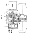
- Fig. 1 is a schematic structural view showing a hybrid transmission to which a control system according to the present invention is applied.
- Fig. 2 is a lever diagram employed for obtaining a revolution balance expression and a torque balance equation of the hybrid transmission shown in Fig. 1.
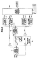
- Fig. 3 is a block diagram showing the control system for the hybrid transmission.
- Fig. 4 is a block diagram showing a shift control executed by a hybrid controller of the control system shown in Fig. 3.
- Fig. 5 is a graph showing an optimal fuel consumption curve and iso-output curves of an engine employed together with the control system.
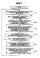
- Fig. 6 is a flowchart showing a control program executed by a motor/generator control command calculating section shown in Fig. 4.
- Fig. 7 is a flowchart showing another control program employed in a second embodiment.
- Fig. 8 is a lever diagram showing a condition of generating an unexpected shift of a hybrid transmission due to an unexpected increase of an engine torque.
- Fig. 9 is a lever diagram employed for explaining a method of preventing the unexpected shift by executing the control program shown in Fig. 6.
- FIGs. 1 through 9. there are shown embodiments of a control system for a hybrid transmission in accordance with the present invention.
- Figs. 1 and 6 show a first embodiment of the control system for the hybrid (automatic) transmission in accordance with the present invention.
- the hybrid transmission is adapted to a transaxle of a front-wheel-drive vehicle.
- the hybrid transmission comprises a transmission case 1, a Ravigneaux planetary gearset 2, and a compound-current double-layer motor 4 constructing first and second motor/generators MG1 and MG2.
- Ravigneaux planetary gearset 2 is built in transmission case 1 so as to be located at a left-hand side of an internal combustion engine (prime mover) ENG along an axial direction of transmission case 1 in Fig. 1.
- compound-current double-layer motor 4 is built in a transmission case 1 so as to be located at the left-hand side of Ravigneaux planetary gearset 2 along the axial direction of transmission case 1 in Fig. 1.
- Ravigneaux planetary gearset 2 engine ENG and compound-current double-layer motor 4 are coaxially arranged on a main axis of transmission case 1.
- a counter shaft 5 and a differential gear device 6 are also built in transmission case 1 so as to be parallel with the main axis while being offset from the main axis.
- Ravigneaux planetary gearset 2 is of a compound planetary gear train where a single-pinion planetary gearset 7 is combined with a double-pinion planetary gearset 8, and common long pinions P1 and a common ring gear R are commonly employed in two planetary gearsets 7 and 8.
- Single-pinion planetary gearset 7 has a structure that common long pinions P1 are meshed with a sun gear Ss.
- Double-pinion planetary gearset 8 comprises a sun gear Sd. a ring gear R, common long pinions P1, and large-diameter short pinions P2.
- Double-pinion planetary gearset 8 has a structure that short pinions P2 are meshed with sun gear Sd, ring gear R and common long pinions P1.
- Pinions P1 and P2 of the two planetary gearsets 7 and 8 are rotatably mounted or supported on shafts that integrally project from a common carrier C.
- Ravigneaux planetary gearset 2 is mainly constituted by four rotating members, that is, sun gear Sd, sun gear Ss, ring gear R, and carrier C.
- Ravigneaux planetary gearset 2 is a two-degree-of-freedom differential mechanism having four rotating elements.
- the sequence of revolution speeds of the rotating members is arranged in the sequence of sun gear Ss, ring gear R, carrier C and sun gear Sd.
- the differential mechanism is not limited to Ravigneaux planetary gearset 2 and may be freely selected from other gear mechanisms.
- Compound-current double-layer motor 4 comprises an inter rotor 4ri, an annular outer rotor 4ro surrounding inner rotor 4ri and a stator coil 4s.
- Inner and outer rotors 4ri and 4ro are coaxially arranged with each other at the rear axial end (the left-hand end) of transmission case 1 and rotatably supported in transmission case 1.
- Annular stator coil 4s acting as a stator of compound-current double-layer motor 4 is disposed in an annular space defined between the outer periphery of inner rotor 4ri and the inner periphery of outer rotor 4ro and fixedly connected to transmission case 1.
- compound multiphase alternating current (AC) multi-layer (double-layer) motor 4. which has multiple motors (two rotors in this embodiment) and is driven by compound multiphase AC, is employed as first and second motor/generator MG1 and MG2. Further, compound-current double-layer motor 4 is arranged such that the number of pole pairs of inner rotor 4ri is different from the number of pole pairs of outer rotor 4ro. Outer and inner rotors 4ro and 4ri of first and second motor/generators MG1 and MG2 are therefore driven independently of each other in revolution speed and in revolution direction by compounding a control current applied to one of the motor/generator set and a control current applied to the other.
- AC alternating current
- double-layer motor 4 which has multiple motors (two rotors in this embodiment) and is driven by compound multiphase AC
- each of motor/generators MG1 and MG2 functions as an electric motor which outputs a rotational force having a revolution direction corresponding to a current direction and a revolution speed (including a stopping state) corresponding to a current strength of the supplied current.
- each of first and second motor/generators MG1 and MG2 functions as a generator which outputs an electric power corresponding to the magnitude of torque applied by way of an external force.
- sun gear Ss, ring gear R, carrier C and sun gear Ss which are four rotating members of Ravigneaux planetary gearset 2, are connected to first motor/generator MG1 (outer rotor 4ro), engine ENG acting as a prime mover, an output OUT connected to a wheel driveline including differential gear device 6, and second motor/generator MG2 (inner rotor 4ri), respectively.
- first motor/generator MG1 outer rotor 4ro
- engine ENG acting as a prime mover an output OUT connected to a wheel driveline including differential gear device 6, and second motor/generator MG2 (inner rotor 4ri), respectively.
- This mentioned sequence of the four rotating members are arranged in the sequence of the revolution speeds.
- Ring gear R acts as an input element through which the power of engine ENG is inputted to the hybrid transmission. Therefore, ring gear C is connected to a crankshaft 9 of engine ENG through a clutch 3.
- Sun gear Sd is connected to second motor/generator MG2 (inner rotor 4ri) through a shaft 11.
- Sun gear Ss is connected to first motor/generator MG1 (outer rotor 4ro) through a hollow shaft 14 which is coaxial with shaft 11.
- carrier C In order to operate carrier C as an output element for outputting the driving force (rotational force) to the wheel driveline (OUT), carrier C is connected to an output gear 14 through a hollow shaft 13, and output gear 14 is meshed with a counter gear 15 integrally connected to a counter shaft 5 which is rotatably supported by transmission case 1.
- a final-drive pinion 18 is also integrally connected to counter shaft 5 and is meshed with a final-drive ring gear 17.
- the output rotational force outputted from the hybrid transmission is transmitted to final differential gear device through a final drive gearset constructed by final drive pinion 16 and final drive ring gear 17, and further distributed to right and left wheels 18 through differential gear device 6.
- the above-discussed hybrid transmission can be represented by a lever diagram shown in Fig. 2.
- a horizontal axis of the lever diagram corresponds to a distance ratio among the rotating members which ratio is determined from a gear ratio of planetary gearsets 7 and 8. More specifically, a distance ratio between sun gear Ss and ring gear R is denoted by ⁇ and a distance ratio between carrier C and sun gear Sd is denoted by ⁇ , on the presumption that a distance between ring gear R and carrier C is set at 1.
- a vertical axis of the lever diagram represents revolution speeds of the respective rotating members, that is, a revolution speed (an engine revolution speed) Ne of ring gear R, a revolution speed Nm1 of sun gear Ss (first motor/generator MG1), an output revolution speed No at output (OUT) from carrier C, and a revolution speed NM2 of sun gear Sd (second motor/generator MG2).
- a revolution speed (an engine revolution speed) Ne of ring gear R a revolution speed Nm1 of sun gear Ss (first motor/generator MG1)
- an output revolution speed No at output (OUT) from carrier C and a revolution speed NM2 of sun gear Sd (second motor/generator MG2).
- revolution speeds of two of four rotating members are determined, the revolution speeds of the other rotating members are also determined.
- Fig. 2 further shows torques of the respective rotating members, that is, an engine torque Te, torques Tm1 and Tm2 of first and second motor/generators MG1 and MG2, an output torque To of output (OUT), in the form of vectors directed along the vertical direction in the lever diagram.
- an input rotation system connected to ring gear R includes engine ENG
- the rotational inertia of the input revolution system is large.
- the output rotation system connected to carrier C includes the wheels 18 and differential gear device 6, the rotational inertia of an output rotation system is also large.
- barycenter (center of gravity) G of the lever is located between ring gear R (engine ENG) and carrier C (output OUT) as shown in Fig. 2. This position of barycenter G of the lever is represented by a distance Xgc from sun gear Ss to barycenter G.
- first and second motor/generators MG1 and MG2 are constructed by compound-current two-layer motor as shown in Fig. 2, the invention is not limited to these first and second motor/generators MG1 and MG2 and may be constructed by independent sets of a rotor and a stator, and the sets may be disposed by offsetting in the diametrical direction.
- the shift control system of the hybrid transmission comprises a hybrid controller 21 which supplies a command relating to target engine torque tTe to an engine controller 22.
- Engine controller 22 controls engine ENG so that the target torque is generated by engine ENG.
- Hybrid controller 21 supplies a signal indicative of a combination of a torque command tTm1' of first motor/generator MG1 and a revolution speed command tNm2' of second motor/generator MG2, or a signal indicative of a combination of a revolution speed command tNm1' of first motor/generator MG1 and a torque command tTm1' of second motor/generator MG2, to motor controller 23.
- Motor controller 23 controls first and second motor/generators MG1 and MG2 through the control of an inverter 24 and a battery 25 according to the received signal so as to achieve the aimed combination of the torque command and the revolution speed command.
- Hybrid control 21 receives a signal indicative of outputted an accelerator opening APO detected by an accelerator opening sensor 26 from an depression quantity of an accelerator pedal, a signal Indicative of a vehicle speed VSP detected a vehicle speed sensor 27, signals indicative of actual torques Tm1 and Tm2 of first and second motor/generators MG1 and MG2, which are respectively detected by torque detectors 28 and 29, signals indicative of actual revolution speeds Nm1 and Nm2 of first and second motor/generators MG1 and MG2 which are respectively detected by revolution speed detectors 30 and 31, and a signal indicative of engine revolution speed Ne detected by an engine speed sensor 32. These signals outputted from torque detectors 28 and 29 and revolution speed detectors 30 and 31 are also supplied to motor controller 23. Motor controller 23 executes a feedback control according to the signals of detectors 28 through 31 and differences between the actual value and the command value of the torque and the revolution speed so as to bring the actual value closer to the command value.
- Hybrid controller 21 executes a control of the hybrid transmission by executing a processing shown by a block diagram in Fig. 4, on the basis of the above-discussed input information.
- a target driving torque calculating section 41 shown in Fig. 4 calculates a target driving torque tTd demanded by a driver from accelerator opening APO and vehicle speed VSP and by a known map retrieval method.
- a target engine (prime mover) output calculating section 42 calculates a drive axle revolution speed Nd by multiplying vehicle speed VSP and a constant Kr determined by a wheel radius or the like.
- An engine (prime mover) operating-point determining section 43 determines an engine operating point (tTe, tNe) as a combination of target engine (prime mover) torque tTe and a target engine (prime mover) revolution speed tNe for generating a terget engine (prime mover) output tPe.
- the engine operating point is determined by an optimal fuel consumption control wherein the engine operating point (tTe, tNe) is set at a combination of an engine torque Te and an engine revolution speed Ne by which target engine output tPe is achieved while keeping the minimum fuel consumption, on the basis of an engine performance map shown in Fig. 5.
- Fig. 5 shows a combination of engine torque Te and engine revolution speed Ne, which correspond to the engine output, in the form of iso-output curves.
- Each of points A and B of the graph in Fig. 4 shows the combination of engine torque Te and engine revolution speed Ne by which the engine output on each iso-output curve is generated while keeping the minimum fuel consumption. Therefore, a line, which connects the minimum fuel consumption points A and B on the respective iso-output curves, is the optimal fuel consumption curve.
- engine operating point (tTe, tNe) is obtained on the basis of the optimal fuel consumption control from Fig. 5
- an intersection between the iso-output curve corresponding to target engine output tPe and the optimal fuel consumption curve is determined, for example, at point A.
- a combination of engine torque Te and engine revolution speed Ne is selected corresponding to point A and is determined as an engine operating point (tTe, tNe).
- a first motor/generator (MG1) target torque calculating section 44 calculates a target torque tTm1 of first motor/generator MG1 from target engine torque tTe and a transmission target output torque tTo obtained by dividing target driving torque tTd by final gear ratio Gf, using the following expression (5).
- tTm1 - ⁇ •tTo-(1+ ⁇ )tTe ⁇ /( ⁇ +1+ ⁇ )
- MG2 target torque calculating section 45 calculates a target torque tTm2 of second motor/generator MG1 from target engine torque tTe and transmission target output torque tTo, using the following expression (6).
- tTm2 - ⁇ (1+ ⁇ )tTo- ⁇ •tTe ⁇ /( ⁇ +1+ ⁇ )
- a second motor/generator (MG2) target revolution speed calculating section 46 calculates a target revolution speed tNm2 of second motor/generator MG2 from target engine revolution speed tNe and a transmission output revolution speed No obtained by multiplying driving axle revolution speed Nd and final differential gear ratio Gf, using the following expression (7).
- tTm2 (1+ ⁇ )No- ⁇ •tNe
- a first motor/generator (MG1) target revolution speed calculating section 47 calculates a target revolution speed tNm1 of first motor/generator MG1 from target engine revolution speed tNe and transmission output revolution speed No, using the following expression (8).
- tTm1 (1+ ⁇ )tNe- ⁇ •tNe
- a motor/generator control command calculating section 48 determines which of first and second motor/generators MG1 and MG2 is controlled in torque and which of first and second motor/generators MG1 and MG2 is controlled in revolution speed, by executing the processing shown in Fig. 6.
- motor/generator control command calculating section 48 determines to execute the torque control of first motor/generator MG1 and the revolution speed control of second motor/generator MG2.
- motor/generator control command calculating section 48 outputs a signal indicative of the combination of a torque command tTm1' of first motor/generator MG1 and a revolution speed command tNm2' of second motor/generator MG2, which will be discussed later, to motor controller 23 shown in Fig.
- motor/generator control command calculating section 48 determines to execute the torque control of second motor/generator MG2 and the revolution speed control of first motor/generator MG1, motor/generator control command calculating section 48 outputs a signal indicative of the combination of a torque command tTm2' of second motor/generator MG2 and a revolution speed command tNm1' of first motor/generator MG1, which will be discussed later, to motor controller 23 shown in Fig. 3.
- motor/generator control command calculating section 48 of hybrid controller 21 sets target torque tTm1 of first motor/generator MG1 at torque command tTm1' and target revolution speed tNm2 of second motor/generator MG2 at revolution speed command tNm2' so as to execute the torque control of first motor/generator MG1 and the revolution speed control of second motor/generator MG2. Further, controller 21 outputs the signal indicative of the combination of torque command tTm1' and revolution speed command tNm2' to motor controller 23.
- step S2 hybrid controller 21 determines whether or not an actual torque Tm2 of second motor/generator MG2 under the revolution speed control becomes saturated, that is, whether actual torque Tm2 is in a saturated state out of a range between upper and lower limits.
- the program returns to step S1 to continue the control of first and second motor/generators MG1 and MG2 by continuously executing the direct power distribution.
- controller 21 changes the torque control of first motor/generator MG1 to the revolution speed control and the revolution speed control of second motor/generator MG2 to the torque control by executing steps S3 through S5.
- hybrid controller 21 starts the revolution speed control of first motor/generator MG1 by setting an initial value of revolution speed command tNm1' at actual revolution speed Nm1 of first motor/generator MG1.
- hybrid controller 21 calculates revolution speed command tNm1' so as to smoothly vary the actual revolution speed from the initial value to target revolution speed tNm1, and outputs the obtained revolution speed command tNm1' to motor controller 23.
- hybrid controller 21 starts the torque control of second motor/generator MG2 by setting an initial value of torque command tTm2' at actual torque Tm2 of second motor/generator MG2.
- hybrid controller 21 calculates torque command tTm2' so as to smoothly vary the actual torque from the initial value to target torque tTm2, and outputs the obtained torque command tTm2' to motor controller 23.
- hybrid controller 21 executes the revolution speed control of first motor/generator MG1 by setting revolution speed command tNm1' at target revolution speed tNm1 and executes the torque control of second motor/generator MG2 by setting torque command tTm2' at target torque tTm2. Then, hybrid controller 21 outputs a signal indicative of the combination of revolution speed command tNm1' of first motor/generator MG1 and torque command tTm2' of second motor/generator MG2 to motor controller 23.
- step S6 subsequent to the execution of step S5, hybrid controller 21 determines whether or not an actual torque Tm1 of first motor/generator MG1 under the revolution speed control becomes saturated, that is, whether actual torque Tm1 is in a saturated state out of a range between upper and lower limits.
- the program returns to step S5 to continue the control of first and second motor/generators MG1 and MG2 by continuously executing the direct power distribution.
- controller 21 changes the revolution speed control of first motor/generator MG1 to the torque control and the torque control of second motor/generator MG2 to the revolution speed control by executing steps S7, S8 and S1.
- hybrid controller 21 starts the torque control of first motor/generator MG1 by setting an initial value of torque command tTm1' at actual torque Tm1 of first motor/generator MG1.
- hybrid controller 21 calculates torque command tNm1' so as to smoothly vary the actual torque from the initial value to target torque tTm1, and outputs the obtained torque command tNm1' to motor controller 23.
- hybrid controller 21 starts the revolution speed control of second motor/generator MG2 by setting an initial value of revolution speed command tNm2' at actual revolution speed Nm2 of second motor/generator MG2.
- hybrid controller 21 calculates revolution speed command tTm2' so as to smoothly vary the actual revolution speed from the Initial value to target revolution speed tNm2, and outputs the obtained revolution speed command tNm2' to motor controller 23.
- hybrid controller 21 executes the torque control of first motor/generator MG1 by setting torque command tTm1 at target torque tTm1 and executes the revolution speed control of second motor/generator MG2 by setting revolution speed command tNm2' at target revolution speed tNm2. Then, hybrid controller 21 outputs a signal indicative of the combination of torque command tTm1' of first motor/generator MG1 and revolution speed command tNm2' of second motor/generator MG2 to motor controller 23.
- Fig. 8 shows that actual torque Tm2 of second motor/generator MG2 under the revolution speed control becomes saturated by the increase of torque Tm2 by a quantity dTm2, as a result that an error of the actual torque of engine EGN relative to the torque command is caused by the disturbance or the like during when the torque control of first motor/generator MG1 and the revolution speed control of second motor/generator MG2 are being executed.
- controller 21 executes an unexpected shift for varying the state of the lever from a lever state shown by a continuous line in Fig. 8 to a lever state shown by a two-dot chain line in Fig. 8, and therefore the output torque To is increased by an increase dTo and does not approach the desired value.
- the lever state is maintained at a state shown by a continuous line in Fig. 9 which corresponds to the state shown by the continuous line in Fig. 8. Consequently, this control according to the present invention removes an afraid that an unexpected shift is executed by unexpected increase dTe due to the disturbance of the engine torque and that an change of output torque To is caused thereby.
- the first embodiment of the shift control system is arranged such that torque command tTm2' (tTm1') of the corresponding motor/generator MG2 (MG1) to be changed from the revolution speed control to the torque control is gradually approached from actual torque Tm2 (Tm1) at a moment just before the changeover to target torque tTm2 (tTm1) by executing steps S3 and S4, or steps S7 and S8, and that revolution speed command tNm1' (tNm2') of the corresponding motor/generator MG1 (MG2) to be changed from the torque control to the revolution speed control is gradually approached from actual revolution speed Nm1 (Nm2) at a moment just before the changeover to target revolution speed tNmt (tNm2) by executing steps S3 and S4 or steps S7 and S8.
- this arrangement prevents the quick changes of the torque and the revolution speed of first and second motor/generators MG1 and MG2 even when the changeover of the control mode for each of first and second motor/generators MG1 and MG2, and thereby preventing the generation of shocks.
- FIG. 7 there is discussed a second embodiment of the shift control system for the hybrid transmission in accordance with the present invention.
- a flowchart shown in Fig. 7 represents a processing for calculating a motor/generator control command.
- the control executed in the second embodiment is basically the same as that executed in the first embodiment except that the monitored object as to the saturation is different between the first and second embodiment. More specifically, although the processing shown in Fig. 6 of the first embodiment is arranged such that the revolution speed control of the motor/generator under the revolution speed control is changed to the torque control and simultaneously the torque control of the other motor/generator is changed to the revolution speed control when the torque of the corresponding motor/generator under the revolution speed control becomes saturated, the processing shown in Fig.
- step S2 in Fig. 6 is replaced with step S12
- step S6 is replaced with step S16.
- the other steps in Fig. 7 respectively execute operations as the same as those of the steps in Fig. 6. Therefore, the corresponding steps are denoted by the same step reference numerals as the steps in Fig. 6, and only steps S12 and S16 are explained herein.
- step S12 hybrid controller 21 determines whether or not revolution speed Nm2 of second motor/generator MG2 under the torque control becomes saturated.
- the program returns to step S1 to continue the torque control of first motor/generator MG1 and the revolution speed control of second motor/generator MG2.
- the program proceeds to step S3 to execute the changeover from the torque control of first motor/generator MG1 to the revolution speed control and the changeover from the revolution speed control of second motor/generator MG2 to the torque control by executing the steps S3 through S5.
- step S16 hybrid controller 21 determines whether or not revolution speed Nm2 of second motor/generator MG2 under the torque control becomes saturated.
- the program returns to step S5 to continue the revolution speed control of first motor/generator MG1 and the torque control of second motor/generator MG2.
- step S7 the program proceeds to step S7 to execute the changeover from the revolution speed control of first motor/generator MG1 to the torque control and the changeover from the torque control of second motor/generator MG2 to the revolution speed control by executing the steps S6. S7 and S1.
- the shift control is continued by changing the torque control of the motor/generator under the torque control to the revolution speed control when the revolution speed of the motor generator under toe torque control becomes saturated. Therefore the saturation of the revolution speed is solved.
- the revolution speed control of the other motor/generator under the revolution speed control is changed to the torque control so that the other motor/generator continues the output power control. Since the other motor/generator has a margin of the revolution speed relative to the saturation of the revolution speed, there is caused no saturation in the revolution speed of the other motor/generator. Therefore, both motor/generators do not cause the saturation of the revolution speed. Consequently, the shift control system of the second embodiment according to the present invention also solves the above-discussed problem that an unexpected shifting is executed due to the saturation of the revolution speed as same as the saturation of the torque.
Landscapes
- Engineering & Computer Science (AREA)
- Mechanical Engineering (AREA)
- Transportation (AREA)
- Chemical & Material Sciences (AREA)
- Combustion & Propulsion (AREA)
- Power Engineering (AREA)
- General Engineering & Computer Science (AREA)
- Sustainable Development (AREA)
- Life Sciences & Earth Sciences (AREA)
- Sustainable Energy (AREA)
- Automation & Control Theory (AREA)
- Electric Propulsion And Braking For Vehicles (AREA)
- Hybrid Electric Vehicles (AREA)
- Control Of Multiple Motors (AREA)
- Arrangement Of Transmissions (AREA)
- Structure Of Transmissions (AREA)
Applications Claiming Priority (2)
| Application Number | Priority Date | Filing Date | Title |
|---|---|---|---|
| JP2002342572 | 2002-11-26 | ||
| JP2002342572A JP3586697B2 (ja) | 2002-11-26 | 2002-11-26 | ハイブリッド変速機の制御装置 |
Publications (2)
| Publication Number | Publication Date |
|---|---|
| EP1426222A1 true EP1426222A1 (fr) | 2004-06-09 |
| EP1426222B1 EP1426222B1 (fr) | 2005-11-02 |
Family
ID=32310640
Family Applications (1)
| Application Number | Title | Priority Date | Filing Date |
|---|---|---|---|
| EP03026968A Expired - Lifetime EP1426222B1 (fr) | 2002-11-26 | 2003-11-25 | Système de commande d'une transmission hybride |
Country Status (4)
| Country | Link |
|---|---|
| US (1) | US6971968B2 (fr) |
| EP (1) | EP1426222B1 (fr) |
| JP (1) | JP3586697B2 (fr) |
| DE (1) | DE60302127T2 (fr) |
Cited By (3)
| Publication number | Priority date | Publication date | Assignee | Title |
|---|---|---|---|---|
| CN106533270A (zh) * | 2015-09-09 | 2017-03-22 | 山洋电气株式会社 | 电机控制装置 |
| WO2020143978A1 (fr) * | 2019-01-08 | 2020-07-16 | Bayerische Motoren Werke Aktiengesellschaft | Dispositif d'étalonnage de deux moteurs électriques disposés sur un essieu dans des véhicules à moteur à deux essieux |
| CN115782852A (zh) * | 2022-12-29 | 2023-03-14 | 常州易控汽车电子股份有限公司 | 排气制动控制方法、系统、计算设备、存储介质及车辆 |
Families Citing this family (25)
| Publication number | Priority date | Publication date | Assignee | Title |
|---|---|---|---|---|
| US7086977B2 (en) * | 2001-05-03 | 2006-08-08 | Ford Global Technologies, Llc | Transmission arrangements for hybrid electric vehicles |
| US7822524B2 (en) * | 2003-12-26 | 2010-10-26 | Toyota Jidosha Kabushiki Kaisha | Vehicular drive system |
| EP1619063B1 (fr) * | 2004-07-21 | 2009-10-14 | Nissan Motor Company, Limited | Procédé et dispositif de commande du couple d'un moteur électrique pour véhicule automobile |
| JP4239923B2 (ja) * | 2004-08-02 | 2009-03-18 | 日産自動車株式会社 | 電動力伝達装置 |
| JP4179266B2 (ja) * | 2004-11-08 | 2008-11-12 | 日産自動車株式会社 | ハイブリッド4輪駆動システム |
| US20070199744A1 (en) * | 2006-02-28 | 2007-08-30 | Leman Scott A | Power generating and storage system having a common stator |
| WO2007104161A1 (fr) * | 2006-03-15 | 2007-09-20 | Tm4 Inc. | Transmission hybride pour véhicules hybrides |
| ITMI20061157A1 (it) * | 2006-06-15 | 2007-12-16 | Piaggio & C Spa | Metodo di gestione delle modalita' di funzionamento di un gruppo motopropulsore ibrido impiegante lo stesso |
| US7686723B2 (en) * | 2006-08-15 | 2010-03-30 | Ford Global Technologies, Llc | Hybrid electric vehicle and powertrain |
| JP4447613B2 (ja) * | 2007-02-08 | 2010-04-07 | トヨタ自動車株式会社 | ハイブリッド車両の駆動力制御装置 |
| US8150584B2 (en) * | 2009-05-12 | 2012-04-03 | Deere & Company | Generation and starting system |
| US8479851B2 (en) * | 2009-10-27 | 2013-07-09 | Magna Powertrain Of America, Inc. | Electric drive unit with modular motor assembly |
| US8538641B2 (en) * | 2009-12-28 | 2013-09-17 | Tai-Her Yang | Multi-motor drive system with differential speed regulated by CVT |
| JP5287780B2 (ja) * | 2010-03-30 | 2013-09-11 | トヨタ自動車株式会社 | ハイブリッド車両の制御装置 |
| DE102010061479B4 (de) * | 2010-12-22 | 2025-12-31 | Dr. Ing. H.C. F. Porsche Aktiengesellschaft | Antriebsverfahren und Antriebsvorrichtung für ein Hybridfahrzeug |
| CN102556045B (zh) * | 2010-12-31 | 2015-04-15 | 上海汽车集团股份有限公司 | 一种混合动力车辆断油滑行换挡控制方法 |
| JP5705585B2 (ja) * | 2011-02-25 | 2015-04-22 | Ntn株式会社 | 電気自動車 |
| JP5532339B2 (ja) * | 2011-03-09 | 2014-06-25 | アイシン・エィ・ダブリュ株式会社 | 制御装置 |
| US9154067B2 (en) * | 2013-12-19 | 2015-10-06 | Kohler Co. | Torque sharing on paralleled generators |
| DE102016203551B4 (de) | 2016-03-03 | 2019-06-06 | Audi Ag | Differentialgetriebe für ein Kraftfahrzeug |
| CN110023160B (zh) | 2016-12-01 | 2023-02-21 | 康明斯有限公司 | 用于控制混合动力发动机系统的系统和方法 |
| CN110949111B (zh) * | 2018-09-27 | 2023-10-20 | 西安交通大学 | 双转子电机与拉维娜式行星轮系串联式汽车混合动力系统 |
| DE102019123367A1 (de) * | 2019-08-30 | 2021-03-04 | Knorr-Bremse Systeme für Nutzfahrzeuge GmbH | Antriebsstrang für ein Fahrzeug |
| US11884161B2 (en) * | 2021-05-07 | 2024-01-30 | Dana Heavy Vehicle Systems Group, Llc | Drivetrain with infinitely and electrically variable transmission capabilities |
| US11420613B1 (en) * | 2021-05-07 | 2022-08-23 | Dana Heavy Vehicle Systems Group, Llc | Drivetrain with infinitely and electrically variable transmission capabilities |
Citations (3)
| Publication number | Priority date | Publication date | Assignee | Title |
|---|---|---|---|---|
| EP0937600A2 (fr) * | 1998-02-19 | 1999-08-25 | Hitachi, Ltd. | Système de transmission hybride incorporé dans une véhicule ou bicyclette |
| US6253127B1 (en) * | 1998-10-15 | 2001-06-26 | Nissan Motor Co., Ltd. | Engine startup control device and control method |
| US6470983B1 (en) * | 1999-04-27 | 2002-10-29 | Hitachi, Ltd. | Hybrid vehicle |
Family Cites Families (2)
| Publication number | Priority date | Publication date | Assignee | Title |
|---|---|---|---|---|
| JP3262046B2 (ja) * | 1997-09-17 | 2002-03-04 | トヨタ自動車株式会社 | ギヤ機構における歯打ち音の低減方法、動力出力装置およびこの動力出力装置を搭載したハイブリッド車輌 |
| WO2003035421A1 (fr) * | 2001-10-22 | 2003-05-01 | The Timken Company | Transmission electro-mecanique a variation infinie |
-
2002
- 2002-11-26 JP JP2002342572A patent/JP3586697B2/ja not_active Expired - Fee Related
-
2003
- 2003-11-21 US US10/717,894 patent/US6971968B2/en not_active Expired - Lifetime
- 2003-11-25 DE DE60302127T patent/DE60302127T2/de not_active Expired - Lifetime
- 2003-11-25 EP EP03026968A patent/EP1426222B1/fr not_active Expired - Lifetime
Patent Citations (3)
| Publication number | Priority date | Publication date | Assignee | Title |
|---|---|---|---|---|
| EP0937600A2 (fr) * | 1998-02-19 | 1999-08-25 | Hitachi, Ltd. | Système de transmission hybride incorporé dans une véhicule ou bicyclette |
| US6253127B1 (en) * | 1998-10-15 | 2001-06-26 | Nissan Motor Co., Ltd. | Engine startup control device and control method |
| US6470983B1 (en) * | 1999-04-27 | 2002-10-29 | Hitachi, Ltd. | Hybrid vehicle |
Cited By (5)
| Publication number | Priority date | Publication date | Assignee | Title |
|---|---|---|---|---|
| CN106533270A (zh) * | 2015-09-09 | 2017-03-22 | 山洋电气株式会社 | 电机控制装置 |
| CN106533270B (zh) * | 2015-09-09 | 2021-06-11 | 山洋电气株式会社 | 电机控制装置 |
| WO2020143978A1 (fr) * | 2019-01-08 | 2020-07-16 | Bayerische Motoren Werke Aktiengesellschaft | Dispositif d'étalonnage de deux moteurs électriques disposés sur un essieu dans des véhicules à moteur à deux essieux |
| US11850949B2 (en) | 2019-01-08 | 2023-12-26 | Bayerische Motoren Werke Aktiengesellschaft | Device for calibrating two electric motors mounted on one axle in two-axle motor vehicles |
| CN115782852A (zh) * | 2022-12-29 | 2023-03-14 | 常州易控汽车电子股份有限公司 | 排气制动控制方法、系统、计算设备、存储介质及车辆 |
Also Published As
| Publication number | Publication date |
|---|---|
| US6971968B2 (en) | 2005-12-06 |
| DE60302127D1 (de) | 2005-12-08 |
| JP3586697B2 (ja) | 2004-11-10 |
| EP1426222B1 (fr) | 2005-11-02 |
| JP2004176790A (ja) | 2004-06-24 |
| DE60302127T2 (de) | 2006-05-24 |
| US20040149501A1 (en) | 2004-08-05 |
Similar Documents
| Publication | Publication Date | Title |
|---|---|---|
| EP1426222B1 (fr) | Système de commande d'une transmission hybride | |
| JP3823949B2 (ja) | ハイブリッド車のモード遷移制御装置 | |
| JP3641244B2 (ja) | ハイブリッド変速機の変速制御装置 | |
| US6751960B2 (en) | Control system of hybrid transmission | |
| JP3711984B2 (ja) | ハイブリッド車両の制御装置 | |
| JP4888154B2 (ja) | 車両およびその制御方法 | |
| US20050102082A1 (en) | Shift control system of hybrid transmission | |
| US10543829B2 (en) | Hybrid vehicle including electronic control unit configured to correct base driving force using correction driving force | |
| US20060009884A1 (en) | Hybrid vehicle control system | |
| JP4229165B2 (ja) | 車両およびその制御方法 | |
| JP2004239278A (ja) | ハイブリッド変速機 | |
| JP4165596B2 (ja) | 制駆動力制御装置 | |
| JP3938001B2 (ja) | ハイブリッド変速機の異常時制御方法 | |
| JP2004015982A (ja) | ハイブリッド変速機の変速制御装置 | |
| JP2005016570A (ja) | ハイブリッド車のモード遷移制御装置 | |
| JP4299288B2 (ja) | 動力出力装置およびこれを搭載する自動車並びに駆動装置,動力出力装置の制御方法 | |
| JP4825639B2 (ja) | 動力出力装置およびこれを搭載する車両並びに駆動装置,動力出力装置の制御方法 | |
| JP4830987B2 (ja) | 制駆動力制御装置 | |
| JP4259488B2 (ja) | 動力出力装置およびこれを搭載する車両並びにこれらの制御方法 | |
| JP2008179290A (ja) | 動力出力装置およびその制御方法並びに車両 | |
| JP4597043B2 (ja) | 車両および駆動装置並びに車両の制御方法 | |
| JP3885756B2 (ja) | ハイブリッド変速機の変速制御装置 | |
| JP2004270785A (ja) | ハイブリッド変速機の変速制御装置 | |
| JP2004132421A (ja) | ハイブリッド変速機の制御方法 | |
| JP3933081B2 (ja) | ハイブリッド変速機の変速制御装置 |
Legal Events
| Date | Code | Title | Description |
|---|---|---|---|
| PUAI | Public reference made under article 153(3) epc to a published international application that has entered the european phase |
Free format text: ORIGINAL CODE: 0009012 |
|
| 17P | Request for examination filed |
Effective date: 20031125 |
|
| AK | Designated contracting states |
Kind code of ref document: A1 Designated state(s): AT BE BG CH CY CZ DE DK EE ES FI FR GB GR HU IE IT LI LU MC NL PT RO SE SI SK TR |
|
| AX | Request for extension of the european patent |
Extension state: AL LT LV MK |
|
| AKX | Designation fees paid |
Designated state(s): DE FR GB |
|
| GRAP | Despatch of communication of intention to grant a patent |
Free format text: ORIGINAL CODE: EPIDOSNIGR1 |
|
| GRAS | Grant fee paid |
Free format text: ORIGINAL CODE: EPIDOSNIGR3 |
|
| GRAA | (expected) grant |
Free format text: ORIGINAL CODE: 0009210 |
|
| AK | Designated contracting states |
Kind code of ref document: B1 Designated state(s): DE FR GB |
|
| REG | Reference to a national code |
Ref country code: GB Ref legal event code: FG4D |
|
| REF | Corresponds to: |
Ref document number: 60302127 Country of ref document: DE Date of ref document: 20051208 Kind code of ref document: P |
|
| ET | Fr: translation filed | ||
| PLBE | No opposition filed within time limit |
Free format text: ORIGINAL CODE: 0009261 |
|
| STAA | Information on the status of an ep patent application or granted ep patent |
Free format text: STATUS: NO OPPOSITION FILED WITHIN TIME LIMIT |
|
| 26N | No opposition filed |
Effective date: 20060803 |
|
| PGFP | Annual fee paid to national office [announced via postgrant information from national office to epo] |
Ref country code: FR Payment date: 20141110 Year of fee payment: 12 Ref country code: GB Payment date: 20141119 Year of fee payment: 12 Ref country code: DE Payment date: 20141118 Year of fee payment: 12 |
|
| REG | Reference to a national code |
Ref country code: DE Ref legal event code: R119 Ref document number: 60302127 Country of ref document: DE |
|
| GBPC | Gb: european patent ceased through non-payment of renewal fee |
Effective date: 20151125 |
|
| REG | Reference to a national code |
Ref country code: FR Ref legal event code: ST Effective date: 20160729 |
|
| PG25 | Lapsed in a contracting state [announced via postgrant information from national office to epo] |
Ref country code: GB Free format text: LAPSE BECAUSE OF NON-PAYMENT OF DUE FEES Effective date: 20151125 Ref country code: DE Free format text: LAPSE BECAUSE OF NON-PAYMENT OF DUE FEES Effective date: 20160601 |
|
| PG25 | Lapsed in a contracting state [announced via postgrant information from national office to epo] |
Ref country code: FR Free format text: LAPSE BECAUSE OF NON-PAYMENT OF DUE FEES Effective date: 20151130 |