EP1426523A1 - Gerüstboden und Gerüst, Podium oder Tribüne mit einem derartigen Gerüstboden - Google Patents
Gerüstboden und Gerüst, Podium oder Tribüne mit einem derartigen Gerüstboden Download PDFInfo
- Publication number
- EP1426523A1 EP1426523A1 EP03022475A EP03022475A EP1426523A1 EP 1426523 A1 EP1426523 A1 EP 1426523A1 EP 03022475 A EP03022475 A EP 03022475A EP 03022475 A EP03022475 A EP 03022475A EP 1426523 A1 EP1426523 A1 EP 1426523A1
- Authority
- EP
- European Patent Office
- Prior art keywords
- scaffolding
- cross
- scaffold
- floor
- recesses
- Prior art date
- Legal status (The legal status is an assumption and is not a legal conclusion. Google has not performed a legal analysis and makes no representation as to the accuracy of the status listed.)
- Granted
Links
Images




Classifications
-
- E—FIXED CONSTRUCTIONS
- E04—BUILDING
- E04H—BUILDINGS OR LIKE STRUCTURES FOR PARTICULAR PURPOSES; SWIMMING OR SPLASH BATHS OR POOLS; MASTS; FENCING; TENTS OR CANOPIES, IN GENERAL
- E04H3/00—Buildings or groups of buildings for public or similar purposes; Institutions, e.g. infirmaries or prisons
- E04H3/10—Buildings or groups of buildings for public or similar purposes; Institutions, e.g. infirmaries or prisons for meetings, entertainments, or sports
- E04H3/22—Theatres; Concert halls; Studios for broadcasting, cinematography, television or similar purposes
- E04H3/24—Constructional features of stages
-
- E—FIXED CONSTRUCTIONS
- E04—BUILDING
- E04G—SCAFFOLDING; FORMS; SHUTTERING; BUILDING IMPLEMENTS OR AIDS, OR THEIR USE; HANDLING BUILDING MATERIALS ON THE SITE; REPAIRING, BREAKING-UP OR OTHER WORK ON EXISTING BUILDINGS
- E04G1/00—Scaffolds primarily resting on the ground
- E04G1/15—Scaffolds primarily resting on the ground essentially comprising special means for supporting or forming platforms; Platforms
-
- E—FIXED CONSTRUCTIONS
- E04—BUILDING
- E04G—SCAFFOLDING; FORMS; SHUTTERING; BUILDING IMPLEMENTS OR AIDS, OR THEIR USE; HANDLING BUILDING MATERIALS ON THE SITE; REPAIRING, BREAKING-UP OR OTHER WORK ON EXISTING BUILDINGS
- E04G1/00—Scaffolds primarily resting on the ground
- E04G1/15—Scaffolds primarily resting on the ground essentially comprising special means for supporting or forming platforms; Platforms
- E04G1/152—Platforms made of metal or with metal-supporting frame
-
- E—FIXED CONSTRUCTIONS
- E04—BUILDING
- E04G—SCAFFOLDING; FORMS; SHUTTERING; BUILDING IMPLEMENTS OR AIDS, OR THEIR USE; HANDLING BUILDING MATERIALS ON THE SITE; REPAIRING, BREAKING-UP OR OTHER WORK ON EXISTING BUILDINGS
- E04G1/00—Scaffolds primarily resting on the ground
- E04G1/15—Scaffolds primarily resting on the ground essentially comprising special means for supporting or forming platforms; Platforms
- E04G1/153—Platforms made of plastics, with or without reinforcement
-
- E—FIXED CONSTRUCTIONS
- E04—BUILDING
- E04G—SCAFFOLDING; FORMS; SHUTTERING; BUILDING IMPLEMENTS OR AIDS, OR THEIR USE; HANDLING BUILDING MATERIALS ON THE SITE; REPAIRING, BREAKING-UP OR OTHER WORK ON EXISTING BUILDINGS
- E04G21/00—Preparing, conveying, or working-up building materials or building elements in situ; Other devices or measures for constructional work
- E04G21/14—Conveying or assembling building elements
- E04G21/16—Tools or apparatus
- E04G21/166—Landings, receiving platforms
-
- E—FIXED CONSTRUCTIONS
- E04—BUILDING
- E04G—SCAFFOLDING; FORMS; SHUTTERING; BUILDING IMPLEMENTS OR AIDS, OR THEIR USE; HANDLING BUILDING MATERIALS ON THE SITE; REPAIRING, BREAKING-UP OR OTHER WORK ON EXISTING BUILDINGS
- E04G5/00—Component parts or accessories for scaffolds
- E04G5/003—Devices for storing material on the scaffold
-
- E—FIXED CONSTRUCTIONS
- E04—BUILDING
- E04G—SCAFFOLDING; FORMS; SHUTTERING; BUILDING IMPLEMENTS OR AIDS, OR THEIR USE; HANDLING BUILDING MATERIALS ON THE SITE; REPAIRING, BREAKING-UP OR OTHER WORK ON EXISTING BUILDINGS
- E04G7/00—Connections between parts of the scaffold
- E04G7/02—Connections between parts of the scaffold with separate coupling elements
- E04G7/28—Clips or connections for securing boards
-
- E—FIXED CONSTRUCTIONS
- E04—BUILDING
- E04G—SCAFFOLDING; FORMS; SHUTTERING; BUILDING IMPLEMENTS OR AIDS, OR THEIR USE; HANDLING BUILDING MATERIALS ON THE SITE; REPAIRING, BREAKING-UP OR OTHER WORK ON EXISTING BUILDINGS
- E04G1/00—Scaffolds primarily resting on the ground
- E04G1/15—Scaffolds primarily resting on the ground essentially comprising special means for supporting or forming platforms; Platforms
- E04G2001/156—Stackable platforms
Definitions
- the present invention relates to a scaffolding floor for a Scaffolding, podium or a grandstand, in particular system scaffolding with specified system dimensions, or as part of one Work surface with a tread, at least one on the Tread connected web and if necessary Connection unit for detachable connection of the scaffolding floor load-bearing components, in particular scaffolding components.
- the present invention further relates to a scaffold, Podium or grandstand, pallet or work surface with such a scaffold floor.
- the scaffold floors have a U-shaped Cross-section with molded on both long sides, webs pointing downwards. Be about connection units the scaffolding decks at the crossbars of the scaffolding system hooked.
- Such scaffolding floors are in high Quantity used in scaffolding systems and have in proven in the past.
- the present invention the task or that technical problem of specifying a scaffold floor, the while maintaining its economical manufacture the variability in the assembly and use of Scaffolding systems increased, is easy to assemble, a variable Design of scaffold floor areas enables, also at already created scaffolding and opens up possibilities To increase the load of scaffolding and under load to reduce occurring deflections.
- the present Invention is still the task or that underlying technical problem, a scaffolding, podium or a Grandstand to indicate that or the very high Possibilities of variation with regard to the training of Scaffolding floor areas, console areas increased and if necessary, increased loads with lower ones Deflection of the entire scaffolding system enables.
- the scaffolding floor according to the invention is characterized by the features of given independent claim 1.
- advantageous Refinements and developments are the subject of dependent on independent claim 1 directly or indirectly Expectations.
- the scaffolding floor according to the invention is accordingly distinguished characterized in that the web has at least one recess through which a cross-connecting profile rod can be inserted or a connection unit can be connected.
- a particularly preferred embodiment is distinguished characterized in that there are several recesses that in the longitudinal direction of the web in one or more predetermined Grid dimensions are arranged.
- additional elements via connecting units be it Scaffolding components or other within the scope of the activity of a Artisans need materials or equipment to connect at least temporarily in the recess.
- the connection of scaffolding components or others Scaffolding floors with different system length dimensions enables easily, is characterized in that the Length dimensions of the recess in the longitudinal direction alternately have different dimensions.
- an advantageous embodiment characterized in that the grid dimension of the recesses at least is selected in some areas so that an integer A multiple of the grid dimension gives the meter dimension (1000 mm).
- a particularly proven embodiment in practice is characterized in that the pitch of the Recesses 125 mm (millimeters) and the adapter grid dimension Is 197 mm (millimeters).
- the grid dimensions can, however also assume other values.
- advantageous adapter grid dimensions 197 mm + n * 250 mm, whereby n 0, 1, 2, 3, ....
- a preferred embodiment is characterized in that that the recesses have a rounded inner contour, in particular circular and / or elongated inner contour having.
- a further tried and tested design is distinguished characterized in that the recesses are polygonal Inner contour, especially a square or have a rectangular inner contour.
- the under Maintaining the structure of the previously known scaffold profile floors can be used, is characterized by that the scaffold floor is essentially a U-shaped Cross-section with two molded on spaced apart Bridges with recesses and the recesses of both Seen in a side view, the webs are arranged congruently are.
- the scaffold floor is essentially a U-shaped Cross-section with two molded on spaced apart Bridges with recesses and the recesses of both Seen in a side view, the webs are arranged congruently are.
- the scaffold, podium or the invention grandstand according to the invention with on structural components connected scaffolding floors is characterized by the characteristics of the Claim 16 given.
- Advantageous configurations and Further developments are characterized by the features of claim 16 directly or indirectly dependent claims.
- the scaffold, podium or the invention Stand according to the invention is accordingly characterized in that that at least one scaffold floor or at least two arranged side by side or spaced one above the other Scaffolding floors of the type described above are used will come /.
- connection options for elements or Connection profile bars or cross-connection profile bars significantly increased. This leads to connection options which is a variability in terms of scaffolding floor space formation, which also changed afterwards or can be expanded when using the previous Scaffolding floors was not possible.
- a particularly preferred embodiment is distinguished characterized in that at least in the area of a recess releasably connectable connection unit or at least one arranged continuously through congruent recesses Cross connection profile bar for connecting vertical connection profile bars or connecting profile bars is available.
- a Design variant which is characterized by distinguishes that at least two scaffolding floors next to each other are arranged and at least one cross-connection profile bar is present, seen through in a side view congruently arranged recess of both scaffold floors is arranged continuously.
- Vertical connecting profile bars are preferred as cross-connecting profile bars or connecting profile bars Hollow section bars, in particular round tubular bars, are used.
- a preferred embodiment is characterized in that that fuser units are used that the inserted cross connection profile bars in their fix the inserted position releasably.
- One way of Formation of the fuser is this as Train pipe coupling unit, then at the same time it is guaranteed that another vertical connection profile bar can be connected, the above or the scaffolding floor levels underneath are statically involved can connect with each other.
- cross-connecting profile bars use a diameter in Range from 33 to 34 mm (millimeters), especially 33.7 mm (Millimeters), because such profile bars as Series profile bars of the steel industry at low cost To be available.
- the vertical connecting profile bars to be trained as scaffold profile bars that one Diameter in the range of 48 to 49 mm (millimeters), in particular 48.3 mm (millimeters), because this means in Connection with the perforated grid Recesses in the webs are a system-compatible connection option for other components of a scaffolding system can be guaranteed.
- the recesses in the web of the scaffold floors offer the possibility of mounting options for handles To make available by means of which the scaffolding floor can be attached or detached more quickly.
- the scaffolding floor according to the invention also offers Possibility of stacking scaffolding floors through the Use of inserted cross connection profile bars and connected vertical connecting rods To reduce the span of the scaffold floors, especially if if the vertical connection profile bars directly on the Soil or ground are stored what is particularly advantageous at high loads because this significantly reduces the deflections.
- cross-connecting profile bars laterally reinforcement beams, for example Beam profiles to connect what for example about Pipe coupling units are done in a simple manner can, provided the beams to be stiffened as pipes are trained.
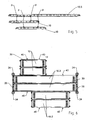
- Fig. 1a is a schematic in one perspective Scaffold floor 10.4 shown, the one in FIG Substantially U-shaped cross section with an upper side existing tread 12 with holes 13 and at the Longitudinally formed edges of the webs pointing downwards 14 has.
- connection units 16 serve the Scaffolding floor 10.4, for example, in a horizontal bar of a scaffolding system that one up has pointing U-shaped profile cross-section.
- Continuous recesses 20, 22 are provided in each web 14 closed inner circumference contour available.
- first Recesses 20 formed which are circular Inner circumference contour with the diameter L1 or H exhibit.
- second recesses 22 which have the height H and the length L2.
- the recesses 20, 22 are symmetrical to the longitudinal center in a predetermined grid arranged in the longitudinal direction of the web.
- the first two arranged symmetrically to the center Recesses 20 have an adapter pitch A.
- the thing about it the first and second connecting to the front Recesses 20, 22 are arranged in the grid dimension R. There is always an alternating circular first Recess 20 and then an elongated hole second recess 22 and so on.
- the recesses 20, 22 shown are exemplary embodiments. There may also be recesses that have a polygonal inner circumference contour, for example in the form of a square or rectangle.
- Fig. 1b the end region of the scaffold floor is 10.4 shown, in which a connection unit on the end face 15 17 is connected in both of them End regions each have a continuous recess 19 and therefore hooked onto the pins on the scaffolding system can be.
- 1c shows the end area of the scaffold plank 10.4 with two connected to the end face 15 Connection units 18 which are part-circular Have cross-sectional contour and are therefore suitable in Round tube profiles to be hung.
- the recesses 20, 22 in can be produced in a simple manner by punching out. 2 runs according to the embodiment of FIG Wall of the web straight up to the recess 20, 22.
- a cross-sectional reinforcement is also possible for everyone in the peripheral area Recess.
- Possible Design variants of such a cross-sectional reinforcement, which are preferably produced by cold working is shown in Figs. 3a to c. 3a the cross-sectional reinforcement is implemented in such a way that one all around in the edge region of the recess 20 convex curvature 42 is impressed in the web wall.
- 3b is a convex curvature 44 in the edge region of the Embossed recess, which is a certain distance from Has recess 20, that is from the area of the convex Curvature 44 up to the edge of the recess a wall protrusion 46 is present.
- 3c is the cross-sectional stiffening implemented in this embodiment by that the web wall in the peripheral edge area of the Recess 20 has a fold 48, such that the Bending 48 is slightly inclined to the inside.
- the scaffold floors 10, 10.1, 10.2, 10.3, 10.4 differ in length in that starting from the scaffolding floor 10 according to FIG. 4e, each further above scaffolding floor one by one predetermined system catch dimension SR has an extended length.
- Fig. 4a is the grid of the recesses 20, 22 in total so that spaced Recesses 20, 22 are present, the distance between the System dimensions S1, S2, S3, for example of a system framework correspond.
- the grid dimension is A 197 mm (millimeters) and the grid dimension R 125 mm (millimeters).
- the grid dimensions S1, S2 and S3 are 1572, 2072 and 2572 mm (Millimeters).
- the system catch dimension SR is 500 mm (Millimeter).
- FIGS. 5 to 8. 6 shows a plan view of the scaffold floor area of a system framework.
- the normal scaffold bay points Vertical posts 24 and horizontal bars 26 on the Connect vertical supports 24 to each other (connections not shown in more detail) and in which the scaffold floors 10 over their Connection units 16 are suspended.
- the two Scaffold floors 10.3 can now be formed in expanded easily with scaffold console surfaces become.
- the appropriate places in Cross direction cross connection profile bars 30 through the corresponding recesses 20, 22 inserted into the inserted condition over the two scaffold floors 10.3 protrude sideways.
- On the cantilevered area of the Cross-connection profile bars 30 are two from the outside Scaffolding floors 10 (shown in Fig.
- the cross-connection profile bars 30 are in the corresponding recesses 20 and 22 of the scaffold floors 10 and 10.2 threaded.
- the Cross-connection profile bars 30 also have a protrusion on both sides, on which fixing units can be detached are connectable, which prevent that between the attached scaffold floors 10 or 10.2 a gap forms.
- the cross-connection profile bars 30 continue to have the effect that the existing scaffolding floors 10.3 des System frameworks interact statically, that is with only one load on one scaffold floor 10.3 the one next to it lying is used for load transfer, which is a Reduction in deflection.
- cross-connection profile bars 30 Round steel tubes are used that have a diameter of 33.7 mm (millimeters), which diameter in Steel profile area is common.
- the Recesses 20, 22 have a height H that is slightly larger is the diameter of the inserted cross-connection profile bars 30th
- the fixing units 40 can preferably be used as pipe coupling units be trained in large numbers in Scaffolding will be used and then at the same time offer the possibility, in addition to the fixation adjacent scaffolding floors also the connection to enable further scaffolding profile elements.
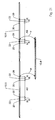
- FIG. 5 is a schematic side view of the Connection of scaffolding floors 10 to a scaffolding floor 10.3 different length offset shown, where scaffold floors 10.3, 10 arranged next to one another in FIG. 5 are arranged one below the other. corresponding Recesses 20, 22, each through a cross-connecting profile bar can be introduced are schematically with Arrows P linked.
- Fig. 8 shows an example of another embodiment of the Formation of console surfaces by pushing on Scaffolding floors 10.2, 10.3 in existing scaffolding floors 10.4 inserted cross-connection profile bars 30. It is also possible to achieve scaffolding floor space extensions, which run at least in areas over two scaffold bays (shown on the underside in FIG. 8).
- Fig. 7 shows, similar to Fig. 5, the arrangement of side by side scaffolding floors with different Length offset partially running over two scaffold bays, here also the scaffold floors arranged next to each other are arranged offset in height in the representation.
- corresponding Recesses 20, 22 through each Cross-connection profile bar can be introduced schematically linked with arrows P.
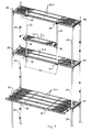
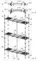
- Fig. 9 is a section of a system framework like for example the Layher Blitz scaffolding system is shown, in the frame components with vertical handles 24 and Horizontal bars 26 are used. There are three in total Scaffold floor levels shown. Every scaffold floor is by two hooked into the horizontal bar 26 Scaffold floors 10.4 formed. Through the recesses in the Bars 14 of the scaffold floors 10.4 are each on the upper and middle scaffold floor level two cross-connecting profile bars 30 approximately in the third points by both scaffold floors 10.4 arranged next to one another, that protrude slightly to the side. In this The dominant area is a vertical connection profile bar 32 via coupling units, not shown to the cross-connection profile rod 30 of the upper and lower scaffolding days connected.
- the Vertical connecting profile bars 32 becomes a supporting structure for Provided on the - as exemplified in Fig. 9 shown - further scaffolding elements as in the present Case console units 38 can be connected.
- the Vertical connecting profile bars 32 are standard scaffold tubes and due to the geometry of the pitch of the recesses the scaffolding floors 10.4 in the longitudinal direction in the scaffolding system dimension S2 arranged. This can be done in a simple manner the two console units 38 a system scaffolding floor 10 can be easily hung.
- a big advantage of this Construction is that the console units 38 practically at any height (arrow h) between the upper and middle scaffold floor can be connected can.
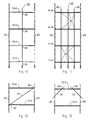
- Fig. 10 is a section from a side view a scaffolding system shown in each scaffolding floor 10.4 seen in a vertical line Cross-connection profile bar 30 by the corresponding Recesses is inserted, with its overhanging A vertical link profile bar 32 in each end region Scaffold floor level is connected to the Soil is guided. This will span the respective scaffold floors 10.4 about halved, which increased Payloads and less deflections under load Consequence.
- FIG. 11 differs from the illustration according to FIG. 10 in that a total of three in this embodiment vertical connecting profile bars 32 on cross connecting profile bars 30 are connected.
- FIG. 12 schematically shows the connection of an as Diagonal bar designed connecting profile bar 34 shown, also via inserted cross-connection profile bars 30 that in appropriate positioning the scaffold floor 10.4 is plugged in, connected.
- Fig. 13 shows the possibility of using inclined connecting profile bars 34, each on a cross-connecting profile bar 30 and a vertical post 24 are connected, to produce rigid frame corners.
- connection units 54 can for example Pipe coupling units, provided that the top chord as Pipe profile is formed.
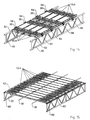
- FIG. 15 Another variant for the formation of a Scaffolding floor area between two lattice girders 60 is shown in FIG. 15 is shown schematically in one perspective.
- Approximately in the third points are parallel to Lattice girder 60 through the recesses of the webs Scaffolding floors 10.4 cross-connecting profile bars 30 inserted, which the scaffold floors 10.4 arranged side by side to one connect common plate. Even with this construction loads that are on a scaffolding floor 10.4 occur not only from this one scaffold floor removed but on neighboring scaffolding floors 10.4 distributed.
- FIG. 16a and b schematically show a cross section Possibility of 10.4 in simple way to raise. This is parallel to Longitudinal edge of the scaffold floor 10.4 16a as I-profile 70 or as tubular profile 72 16b can be formed. Profiles 70, 72 become a static load under load used that through the web recesses 20 of the Scaffold floor 10.4 at least one cross-connecting profile bar 30 is inserted, the respective end region with the I-profile 70 or the tube profile 72 is connected. Connection units 74.1 and 74.2 are used, the corresponding geometry of the respective profile 70, 72 are adapted.
- Fig. 17 is a section of a schematic Scaffolding system shown, also in the vertical connection profile connecting rods 32 on cross-connecting profile bars 30 are connected, similar to that in FIGS. 10 and 11 illustrated embodiments.
- the Connection profile bars 32 not to the bottom area led but couple three superimposed Scaffolding floor levels, so that one is on a scaffolding floor level load on three scaffold floor levels distributed.
- the vertical connection profile bars 32 are on both the front and on the Back of the system scaffold on the cross connection profile bars 30 connected.
- Fig. 18 shows schematically the formation of a pallet, the in the exemplary embodiment by five arranged side by side Scaffolding floors 10.4 is formed, being in the recesses the webs a total of four cross-connecting profile bars 30 in relatively narrow grid are inserted. Means for solvable Fixing the cross-connection profile bars 30 in the inserted State are not shown in Fig. 18 in more detail.
- FIG. 19 schematically shows the formation of a so-called Scissor table, as a work surface
- two scaffold floors arranged side by side 10.4 are present.
- Through the recesses in the scaffolding floors 10.4 are in the end area and in the third points overall four cross-connection profile bars 30 inserted, so that two adjacent scaffold floors 10.4 as one Plate act.
- a Vertical rod 80 via pipe coupling units, not shown connected, which is supported on the floor.
- Diagonal bars 82 are present, each together with the Scaffold floor 10.4 and the vertical rod 80 a rigid Form corner.
- the diagonal bars 82 are each on the top the cross connection profile bars inserted in the third points 30 connected and underside in the lower End portion of the vertical rod 80 connected.
- Fig. 20 shows schematically the simple connection of a Railing construction 84 consisting of vertical supports 86 and Horizontal bolts 88 to a scaffolding floor 10.4 Web recesses by the simple way Vertical stems 36 in the protruding end area from in Recesses of the scaffolding floor 10 inserted cross-connecting profile bars 30 can be connected.
- Inserted cross-connection profiles can also be used as Lifting protection for scaffolding floors can be used by the Profiles over connected elements firmly to the floor get connected.
- Fig. 21 two are arranged one behind the other Steel scaffold floors shown 10.5, each one have enlarged adapter spacing AS and each in their third points three arranged in grid dimension R. Have recesses 20, 22.
- the grid dimension is in the illustrated embodiment 1197 mm (millimeters) and the grid dimension R 125 mm (Millimeters).
- a scaffold floor 10.4 Underneath is a scaffold floor 10.4, the side is offset to the two scaffolding floors 10.5 and via cross connection profile bars, not shown the two scaffold floors 10.5 is coupled.
- corresponding Recesses 20, 22 through which a cross-connecting profile rod can be introduced are schematically with Arrows P linked.
Landscapes
- Engineering & Computer Science (AREA)
- Architecture (AREA)
- Civil Engineering (AREA)
- Structural Engineering (AREA)
- Mechanical Engineering (AREA)
- Multimedia (AREA)
- Bridges Or Land Bridges (AREA)
- Floor Finish (AREA)
- Movable Scaffolding (AREA)
- Mutual Connection Of Rods And Tubes (AREA)
- Ladders (AREA)
- Graft Or Block Polymers (AREA)
- Polyurethanes Or Polyureas (AREA)
- Transition And Organic Metals Composition Catalysts For Addition Polymerization (AREA)
- Glass Compositions (AREA)
Abstract
Description
- Fig. 1a, b, c
- schematische Perspektivdarstellung eines Gerüstbodens, der einen U-förmigen Querschnitt mit nach unten weisenden Stegen besitzt, wobei innerhalb der Stege in Längsrichtung rasterförmig angeordnete Ausnehmungen vorhanden sind, jeweils mit unterschiedlicher Ausgestaltung von stirnseitig vorhandenen Anschlusseinheiten,
- Fig. 2
- schematischer Querschnitt durch den Gerüstboden gemäß Fig. 1a entlang Schnittführung I-I,
- Fig. 3a, b, c
- schematischer Detailquerschnitt durch den Steg des Gerüstbodens gemäß Detail I von Fig. 2 mit konstruktiv unterschiedlicher Ausbildung einer Querschnittsversteifung im Randbereich der Ausnehmung,
- Fig. 4a bis e
- schematische Seitenansicht von Gerüstböden mit rasterförmig im Steg in Längsrichtung angeordneten Ausnehmungen mit unterschiedlichen Systemmaßen,
- Fig. 5
- schematische Seitenansicht von Gerüstböden, die nebeneinander anordenbar sind und über nicht dargestellte Querverbindungsprofilstäbe miteinander koppelbar sind, wobei die nebenseitig angeordneten Gerüstböden nach unten versetzt dargestellt sind,
- Fig. 6
- schematische Draufsicht auf eine Gerüstbodenfläche, bei der konsolflächenbildende Gerüstböden über vorhandene Querverbindungsprofilstäbe aufgesteckt sind,
- Fig. 7
- schematische Seitenansicht von Gerüstböden, die nebeneinander anordenbar sind und über nicht dargestellte Querverbindungsprofilstäbe miteinander koppelbar sind, wobei die nebenseitig angeordneten Gerüstböden nach unten versetzt dargestellt sind und gleichzeitig die Kopplung von nebeneinander liegenden Gerüstböden über zwei Systemfelder des Gerüstsystems hinweg dargestellt ist,
- Fig. 8
- schematische Draufsicht auf eine Gerüstbodenfläche, bei der konsolflächenbildende Gerüstböden über vorhandene Querverbindungsprofilstäbe aufgesteckt sind,
- Fig. 9
- schematische ausschnittsweise Perspektivdarstellung aus einem Gerüstsystem mit drei Gerüstetagen, wobei unter Einsatz von Gerüstböden mit im Steg vorhandenen Ausnehmungen in Verbindung mit durch die Stegausnehmung gesteckten Querverbindungsprofilstäben die Ausbildung von Konsolbereichen dargestellt ist (unterste Gerüstetage in Fig. 9) und unter Einsatz von Gerüstböden mit Ausnehmungen in Verbindung mit in die Ausnehmung eingesteckten Querverbindungsprofilstäben und an die Querverbindungsprofilstäbe angeschlossenen Vertikalverbindungsprofilstäben der Einsatz einer an den Vertikalverbindungsprofilstäben höhenmäßig beliebig anordenbaren Konsoleinrichtung dargestellt ist (mittlere und obere Gerüstetage gemäß Fig. 9),
- Fig. 10
- schematischer Teilausschnitt aus einem Gerüstsystem, bei dem übereinander angeordnete Gerüstbelagsebenen durch Einsatz eines Vertikalverbindungsprofilstabes, der an in die Ausnehmungen der Gerüstböden eingesteckte Querverbindungsprofilstäbe angeschlossen und der auf dem Boden gelagert ist,
- Fig. 11
- schematischer Teilausschnitt aus einem Gerüstsystem, bei dem übereinander angeordnete Gerüstbelagsebenen durch Einsatz von drei Vertikalverbindungsprofilstäben, die in die Ausnehmungen der Gerüstböden eingesteckte Querverbindungsprofilstäbe angeschlossen sind,
- Fig. 12
- schematische ausschnittsweise Seitenansicht eines Gerüstsystems, bei dem über in die Ausnehmungen zweier übereinander angeordneter Gerüstböden eingesteckter Querverbindungsprofilstäbe der Anschluss eines Diagonalprofilstabes dargestellt ist,
- Fig. 13
- schematische ausschnittsweise Seitenansicht eines Gerüstsystems, bei dem über in die Ausnehmungen eines Gerüstbodens eingesteckten Querverbindungsprofilstäbe der Anschluss von zwei Diagonalprofilstäben zur Ausbildung von biegesteifen Ecken dargestellt ist,
- Fig. 14
- schematische Detailperspektivdarstellung von nebeneinander angeordneten Gerüstböden, die durch in die Ausnehmungen der Stege eingesteckten Querverbindungsprofilstäbe statisch miteinander verbunden werden, wobei die Querverbindungsprofilstäbe an Obergurte von Gitterträgern angeschlossen sind (parallele Anordnung der Gerüstböden zum Gitterträger),
- Fig. 15
- schematische Detailperspektivdarstellung von nebeneinander angeordneten Gerüstböden, die durch Einstecken von Querverbindungsprofilstäben statisch miteinander in Wirkverbindung gebracht werden und die mit ihren Anschlusseinheiten in Obergurte von Gitterträgern eingehängt sind (senkrechte Anordnung der Gerüstböden zum Gitterträger) ,
- Fig. 16a, b
- schematische Querschnittsdarstellung durch einen Gerüstboden mit seitlich über in die Ausnehmungen der Stege des Gerüstbodens eingesteckten Querverbindungsprofilstäbe angeschlossenen Tragprofilen zur Erhöhung der Tragfähigkeit und zur Verringerung der Durchbiegung,
- Fig. 17
- schematische Detailperspektivdarstellung eines Ausschnitts aus einem Gerüstsystem, bei dem drei übereinander angeordnete Gerüstetagen über in die Ausnehmungen der Stege eingesteckten Querverbindungsprofilstäbe mit jeweils daran angeschlossenen Vertikalverbindungsprofilstäben statisch miteinander gekoppelt werden,
- Fig. 18
- schematische Perspektivdarstellung der Ausbildung einer Palette, gebildet durch nebeneinander angeordnete Gerüstböden, die über in die Ausnehmungen der Stege eingesteckten Querverbindungsprofilstäbe statisch mitwirkend miteinander verbunden sind,
- Fig. 19
- schematische Seitenansicht einer Arbeitsbodenfläche, die aus mehreren nebeneinander angeordneten und mittels in die Ausnehmungen eingesteckten Querverbindungsprofilstäben gekoppelten Gerüstböden besteht, wobei an die Querverbindungsprofilstäbe eine tragende Unterkonstruktion angeschlossen ist,
- Fig. 20
- schematische Seitenansicht einer Arbeitsbodenfläche gemäß Fig. 19 mit oberseitig an in die Ausnehmungen eingesteckten Querverbindungsprofilstäben angeschlossener Geländervorrichtung und
- Fig. 21
- schematische Seitenansicht von zwei hintereinander angeordneten Gerüstböden und einem Gerüstboden, der neben den beiden Gerüstböden anordenbar ist und über nicht näher dargestellte Querverbindungsprofilstäbe angekoppelt ist, wobei der nebenseitig angeordnete Gerüstboden nach unten versetzt dargestellt ist.
Claims (34)
- Gerüstboden (10) für ein Gerüst, Podium oder eine Tribüne, insbesondere Systemgerüst mit vorgegebenen Systemmaßen (S1, S2, S3), oder als Teil einer Arbeitsfläche mitdadurch gekennzeichnet, dasseiner Lauffläche (12),zumindest einem an die Lauffläche (12) angeschlossenen Steg (14) und gegebenenfallsAnschlusseinheit (16) zum lösbaren Anschluss des Gerüstbodens (10) an tragende Bauteile, insbesondere Gerüstbauteile,
der Steg (14) zumindest eine Ausnehmung (20, 22) aufweist, durch die hindurch ein Querverbindungsprofilstab (30) einsteckbar ist oder eine Anschlusseinheit anschließbar ist. - Gerüstboden nach Anspruch 1,
dadurch gekennzeichnet, dass
mehrere Ausnehmungen (20, 22) vorhanden sind, die in Steglängsrichtung in einem oder mehreren vorgegebenen Rastermaß/en (A, R) angeordnet sind. - Gerüstboden nach Anspruch 2,
dadurch gekennzeichnet, dass
die Längenabmessungen (L1, L2) der Ausnehmung (20, 22) in Längsrichtung alternierend ein unterschiedliches Maß aufweisen. - Gerüstboden nach Anspruch 2 oder 3,
dadurch gekennzeichnet, dass
die Ausnehmungen (20, 22) symmetrisch zur Längsmitte des Steges (14) rastermäßig angeordnet sind. - Gerüstboden nach einem oder mehreren der Ansprüche 2 bis 4,
dadurch gekennzeichnet, dass
das Rastermaß (R) der Ausnehmungen (20, 22) zumindest bereichsweise so gewählt ist, dass ein ganzzahliges Vielfaches des Rastermaßes (R) das Metermaß (1000 mm) ergibt. - Gerüstboden nach einem oder mehreren der vorstehenden Ansprüche,
dadurch gekennzeichnet, dass
zwei symmetrisch zur Längsmitte des Steges vorhandene Ausnehmungen (20) in einem Adapterrastermaß (A) angeordnet ist, das so groß gewählt ist, dass die Summe aus dem Adapterrastermaß (A) und einem ganzzahligen Vielfachen von dem Rastermaß (R) der übrigen Ausnehmungen (20, 22) ein Systemmaß (S1, S2, S3) des Systemgerüsts ergibt. - Gerüstboden nach Anspruch 5 oder 6,
dadurch gekennzeichnet, dass
das Rastermaß (R) 125 mm (Millimeter) beträgt. - Gerüstboden nach Anspruch 6 oder 7,
dadurch gekennzeichnet, dass
das Adapterrastermaß (A) 197 mm (Millimeter) + n * 250 mm (Millimeter) beträgt, wobei n = 0, 1, 2, 3, ... . - Gerüstboden nach einem oder mehreren der vorstehenden Ansprüche,
dadurch gekennzeichnet, dass
die Ausnehmungen (20, 22) eine gerundete Innenkontur, insbesondere kreis- und/oder langlochförmige Innenkontur aufweisen. - Gerüstboden nach einem oder mehreren der vorstehenden Ansprüche 1 bis 8,
dadurch gekennzeichnet, dass
die Ausnehmungen eine polygonale Innenkontur, insbesondere eine quadratische oder rechteckförmige Innenkontur, aufweisen. - Gerüstboden nach einem oder mehreren der vorstehenden Ansprüche,
dadurch gekennzeichnet, dass
im Randumfangsbereich der jeweiligen Ausnehmung (20, 22) eine Querschnittsversteifung vorhanden ist. - Gerüstboden nach Anspruch 11,
dadurch gekennzeichnet, dass
die Querschnittsversteifung durch eine nach innen oder außen weisende Umkantung gebildet wird. - Gerüstboden nach Anspruch 11,
dadurch gekennzeichnet, dass
die Querschnittsversteifung durch eine konkave oder konvexe Wölbung der Querschnittskontur gebildet wird. - Gerüstboden nach einem oder mehreren der vorstehenden Ansprüche,
dadurch gekennzeichnet, dass
der Gerüstboden (10) im Wesentlichen einen U-förmigen Querschnitt mit zwei beabstandet zueinander angeformten Stegen (16) mit Ausnehmungen (20, 22) aufweist und die Ausnehmungen (20, 22) beider Stege (16) in einer Seitenansicht gesehen kongruent angeordnet sind. - Gerüstboden nach einem oder mehreren der vorstehenden Ansprüche,
dadurch gekennzeichnet, dass
der Gerüstboden aus Stahl, Aluminium oder Kunststoff besteht. - Gerüst, Podium oder Tribüne mit an tragenden Bauelementen angeschlossenen Gerüstböden,
dadurch gekennzeichnet, dass
zumindest ein Gerüstboden (10) oder zumindest zwei nebeneinander oder beabstandet übereinander angeordnete Gerüstböden nach einem oder mehreren der vorstehenden Ansprüche vorhanden ist/sind. - Gerüst, Podium oder Tribüne nach Anspruch 16,
dadurch gekennzeichnet, dass
zumindest im Bereich einer Ausnehmung (20, 22) eine lösbar anschließbare Anschlusseinheit oder zumindest ein durch kongruente Ausnehmungen durchlaufend angeordneter Querverbindungsprofilstab (30) zum Anschluss von Vertikalverbindungsprofilstäben (32) oder Anschlussprofilstäben (34) vorhanden ist. - Gerüst, Podium oder Tribüne nach Anspruch 16 oder 17,
dadurch gekennzeichnet, dass
zumindest zwei Gerüstböden (10) nebeneinander angeordnet sind und zumindest ein Querverbindungsprofilstab (30) vorhanden ist, der durch in einer Seitenansicht gesehen kongruent angeordnete Ausnehmung (20, 22) beider Gerüstböden (10) durchlaufend angeordnet ist. - Gerüst, Podium oder Tribüne nach Anspruch 16, 17 oder 18,
dadurch gekennzeichnet, dass
zumindest übereinander angeordnete aus Gerüstböden (10) bestehenden Gerüstetagen vorhanden sind und zumindest ein Vertikalverbindungsprofilstab (32) vorhanden ist, der an der Anschlusseinheit der Ausnehmung des unteren und des oberen Gerüstbodens oder über eine an einem Querverbindungsprofilstab (30) angeschlossene Anschlusseinheit an den oberen und unteren Gerüstboden angeschlossen ist. - Gerüst, Podium oder Tribüne nach einem oder mehreren der Ansprüche 17 bis 19,
dadurch gekennzeichnet, dass
der Anschlussprofilstab, der Querverbindungsprofilstab (30) und/oder der Vertikalverbindungsprofilstab (32) als Hohlprofilstab, insbesondere als Rundrohrstab, ausgebildet sind. - Gerüst, Podium oder Tribüne nach Anspruch 17,
dadurch gekennzeichnet, dass
der Anschlussprofilstab (34) mit den übrigen Bauteilen der Konstruktion eine biegesteife Ecke oder eine Diagonalenaussteifung bildet. - Gerüst, Podium oder Tribüne nach Anspruch 19,
dadurch gekennzeichnet, dass
zumindest zwei in Längsrichtung beabstandet angeordnete Vertikalverbindungsprofilstäbe (32) vorhanden sind, an die jeweils eine in ihrer Höhe frei verstellbare Konsoleinheit (38) angeschlossen ist. - Gerüst, Podium oder Tribüne nach Anspruch 17 oder 18,
dadurch gekennzeichnet, dass
zumindest zwei beabstandete Querverbindungsprofilstäbe (30) vorhanden sind, die über die Systembreite des Gerüsts, Podiums oder der Tribüne hinausragen, und im auskragenden Bereich zumindest ein weiterer Gerüstboden (10) auf die zumindest zwei Querverbindungsprofilstäbe (30) aufgesteckt ist. - Gerüst, Podium oder Tribüne nach einem oder mehreren der ansprüche 17 bis 23,
dadurch gekennzeichnet, dass
lösbare Fixiereinheiten (40) zum Fixieren der Lage der in die Ausnehmung/en (20, 22) eingesetzten Querverbindungsprofilstäbe (30) vorhanden sind. - Gerüst, Podium oder Tribüne nach Anspruch 24,
dadurch gekennzeichnet, dass
die Fixiereinheiten als Rohrkupplungseinheiten ausgebildet sind. - Gerüst, Podium oder Tribüne nach Anspruch 18,
dadurch gekennzeichnet, dass
die an den Querverbindungsprofilstab (30) angeschlossene Anschlusseinheit zum Anschluss des Vertikalverbindungsprofilstabes (32) als Rohrkupplungseinheit ausgebildet ist. - Gerüst, Podium oder Tribüne nach einem oder mehreren der Ansprüche 17 bis 26,
dadurch gekennzeichnet, dass
die Höhe der Ausnehmung/en (20, 22) unwesentlich größer ist als die Querschnittshöhe des Querverbindungsprofilstabes (30) . - Gerüst, Podium oder Tribüne nach Anspruch 17 oder 18,
dadurch gekennzeichnet, dass
mehrere Querverbindungsprofilstäbe (30) vorhanden sind, an die eine Geländerkonstruktion angeschlossen ist. - Gerüst, Podium oder Tribüne nach Anspruch 17 bis 28,
dadurch gekennzeichnet, dass
der Querschnittverbindungsprofilstab einen Durchmesser im Bereich von 33 bis 34 mm (Millimeter), insbesondere 33,7 mm (Millimeter). aufweist. - Gerüst, Podium oder Tribüne nach Anspruch 17 bis 29,
dadurch gekennzeichnet, dass
derVertikalverbindungsprofilstab (32) oder Anschlussprofilstab (34) als Gerüstprofilstab mit einem Durchmesser im Bereich zwischen 48 und 49 mm (Millimeter), insbesondere 48,3 mm (Millimeter), aufweist. - Palette oder Arbeitsbodenfläche, bestehend aus Gerüstbodenelementen,
dadurch gekennzeichnet, dass
zumindest ein Gerüstboden (10) nach einem oder mehreren der Ansprüche 1 bis 14 vorhanden ist. - Palette oder Arbeitsbodenfläche nach Anspruch 31,
dadurch gekennzeichnet, dass
zumindest zwei Gerüstböden (10) nebeneinander angeordnet sind und zumindest zwei in Längsrichtung beabstandet zueinander in die Ausnehmungen (20, 22) eingesteckte Querverbindungsprofilstäbe (30) vorhanden sind. - Arbeitsbodenfläche nach Anspruch 32,
dadurch gekennzeichnet, dass
an die Querverbindungsprofilstäbe (30) unterseitig eine Stützkonstruktion angeschlossen ist. - Arbeitsbodenfläche nach Anspruch 32 oder 33,
dadurch gekennzeichnet, dass
an die Querverbindungsprofilstäbe (30) oberseitig eine Geländerkonstruktion angeschlossen ist.
Priority Applications (1)
| Application Number | Priority Date | Filing Date | Title |
|---|---|---|---|
| EP08019716A EP2045415B9 (de) | 2002-11-20 | 2003-10-08 | Gerüst, Podium oder Tribüne mit einem Gerüstboden |
Applications Claiming Priority (2)
| Application Number | Priority Date | Filing Date | Title |
|---|---|---|---|
| DE10254033 | 2002-11-20 | ||
| DE10254033A DE10254033A1 (de) | 2002-11-20 | 2002-11-20 | Gerüstboden und Gerüst, Podium oder Tribüne mit einem derartigen Gerüstboden |
Related Child Applications (1)
| Application Number | Title | Priority Date | Filing Date |
|---|---|---|---|
| EP08019716A Division EP2045415B9 (de) | 2002-11-20 | 2003-10-08 | Gerüst, Podium oder Tribüne mit einem Gerüstboden |
Publications (2)
| Publication Number | Publication Date |
|---|---|
| EP1426523A1 true EP1426523A1 (de) | 2004-06-09 |
| EP1426523B1 EP1426523B1 (de) | 2009-08-05 |
Family
ID=32240181
Family Applications (2)
| Application Number | Title | Priority Date | Filing Date |
|---|---|---|---|
| EP03022475A Expired - Lifetime EP1426523B1 (de) | 2002-11-20 | 2003-10-08 | Gerüstboden |
| EP08019716A Expired - Lifetime EP2045415B9 (de) | 2002-11-20 | 2003-10-08 | Gerüst, Podium oder Tribüne mit einem Gerüstboden |
Family Applications After (1)
| Application Number | Title | Priority Date | Filing Date |
|---|---|---|---|
| EP08019716A Expired - Lifetime EP2045415B9 (de) | 2002-11-20 | 2003-10-08 | Gerüst, Podium oder Tribüne mit einem Gerüstboden |
Country Status (4)
| Country | Link |
|---|---|
| EP (2) | EP1426523B1 (de) |
| AT (2) | ATE438773T1 (de) |
| DE (3) | DE10254033A1 (de) |
| ES (2) | ES2362152T3 (de) |
Cited By (5)
| Publication number | Priority date | Publication date | Assignee | Title |
|---|---|---|---|---|
| DE102008015066A1 (de) | 2008-03-19 | 2009-09-24 | Wilhelm Layher Verwaltungs-Gmbh | Belageinheit mit Abhebesicherung und Verfahren zur Sicherung einer Belageinheit gegen Abheben sowie Verfahren zur Entsicherung einer gegen Abheben gesicherten Belageinheit |
| EP2792813A1 (de) * | 2013-04-16 | 2014-10-22 | Mon.zon Development AB | Stabilisierungselement |
| EP1809834B1 (de) * | 2004-11-11 | 2017-02-15 | Zinco GmbH | System als anschlagmöglichkeit für schutzausrüstungen gegen absturz |
| WO2020094504A1 (de) * | 2018-11-06 | 2020-05-14 | Peri Gmbh | Gerüstsystem und verfahren zur herstellung des gerüstsystems |
| RU2800852C2 (ru) * | 2018-11-06 | 2023-07-31 | Пери Се | Система подмостей и способ изготовления системы подмостей |
Families Citing this family (7)
| Publication number | Priority date | Publication date | Assignee | Title |
|---|---|---|---|---|
| NO319365B1 (no) * | 2003-11-12 | 2005-07-18 | Rh Products Int As | Gulvelement for stillas |
| DE202012101000U1 (de) | 2012-03-21 | 2013-03-25 | Wilhelm Layher Verwaltungs-Gmbh | Überlappungs-Anordnung von wenigstens zwei Laufplanken |
| GB2524780B (en) * | 2014-04-02 | 2017-09-13 | David Westlake Peter | Modular scaffold board |
| DE102015108650A1 (de) * | 2015-06-01 | 2016-12-01 | Wilhelm Layher Verwaltungs-Gmbh | Gerüstbodenelement, insbesondere für ein Baugerüst |
| NL2029592B1 (nl) * | 2021-11-02 | 2023-03-31 | Scafom Holding B V | Vloerdeel voor een steiger, en steigersysteem |
| DE102022200448A1 (de) | 2022-01-17 | 2023-07-20 | Peri Se | Unterzug für Gerüstbeläge, Gerüstbelagebene, Verfahren zur Ausbildung einer Gerüstbelagebene sowie Verwendung eines Unterzugs |
| DE102023135895A1 (de) * | 2023-12-19 | 2025-06-26 | Wilhelm Layher Verwaltungs-Gmbh | Verfahren zur vorlaufenden montage eines erweiterungs-gerüstträgers und wenigstens eines sich daran abstützenden erweiterungs-gerüstbodens |
Citations (7)
| Publication number | Priority date | Publication date | Assignee | Title |
|---|---|---|---|---|
| US2676066A (en) * | 1951-05-25 | 1954-04-20 | Woboril Company | Folding swing stage |
| DE1559034A1 (de) | 1965-11-09 | 1969-08-21 | Hans Meisch | Abschlagbares Arbeitsgeruest |
| US3804198A (en) * | 1972-09-07 | 1974-04-16 | J Palumbo | Combination ladder and mudboard |
| JPS6030760A (ja) * | 1983-07-31 | 1985-02-16 | 日綜産業株式会社 | 工事用可搬式歩廊 |
| US4984654A (en) | 1990-05-10 | 1991-01-15 | Carl Anderson | Scaffold safety system |
| DE19515062A1 (de) | 1995-04-27 | 1996-10-31 | Langer Ruth Geb Layher | Gerüstboden |
| US20020139612A1 (en) * | 1999-05-22 | 2002-10-03 | Horst Laug | Ladder with a floor board |
-
2002
- 2002-11-20 DE DE10254033A patent/DE10254033A1/de not_active Withdrawn
-
2003
- 2003-10-08 AT AT03022475T patent/ATE438773T1/de active
- 2003-10-08 DE DE50311773T patent/DE50311773D1/de not_active Expired - Lifetime
- 2003-10-08 AT AT08019716T patent/ATE502171T1/de active
- 2003-10-08 EP EP03022475A patent/EP1426523B1/de not_active Expired - Lifetime
- 2003-10-08 ES ES08019716T patent/ES2362152T3/es not_active Expired - Lifetime
- 2003-10-08 EP EP08019716A patent/EP2045415B9/de not_active Expired - Lifetime
- 2003-10-08 DE DE50313556T patent/DE50313556D1/de not_active Expired - Lifetime
- 2003-10-08 ES ES03022475T patent/ES2329454T3/es not_active Expired - Lifetime
Patent Citations (7)
| Publication number | Priority date | Publication date | Assignee | Title |
|---|---|---|---|---|
| US2676066A (en) * | 1951-05-25 | 1954-04-20 | Woboril Company | Folding swing stage |
| DE1559034A1 (de) | 1965-11-09 | 1969-08-21 | Hans Meisch | Abschlagbares Arbeitsgeruest |
| US3804198A (en) * | 1972-09-07 | 1974-04-16 | J Palumbo | Combination ladder and mudboard |
| JPS6030760A (ja) * | 1983-07-31 | 1985-02-16 | 日綜産業株式会社 | 工事用可搬式歩廊 |
| US4984654A (en) | 1990-05-10 | 1991-01-15 | Carl Anderson | Scaffold safety system |
| DE19515062A1 (de) | 1995-04-27 | 1996-10-31 | Langer Ruth Geb Layher | Gerüstboden |
| US20020139612A1 (en) * | 1999-05-22 | 2002-10-03 | Horst Laug | Ladder with a floor board |
Cited By (7)
| Publication number | Priority date | Publication date | Assignee | Title |
|---|---|---|---|---|
| EP1809834B1 (de) * | 2004-11-11 | 2017-02-15 | Zinco GmbH | System als anschlagmöglichkeit für schutzausrüstungen gegen absturz |
| DE102008015066A1 (de) | 2008-03-19 | 2009-09-24 | Wilhelm Layher Verwaltungs-Gmbh | Belageinheit mit Abhebesicherung und Verfahren zur Sicherung einer Belageinheit gegen Abheben sowie Verfahren zur Entsicherung einer gegen Abheben gesicherten Belageinheit |
| EP2479360A1 (de) | 2008-03-19 | 2012-07-25 | Wilhelm Layher Verwaltungs-GmbH | Belageinheit mit Abhebesicherung und Verfahren zur Sicherung einer Belageinheit gegen Abheben sowie Verfahren zur Entsicherung einer gegen Abheben gesicherten Belageinheit |
| EP2792813A1 (de) * | 2013-04-16 | 2014-10-22 | Mon.zon Development AB | Stabilisierungselement |
| WO2020094504A1 (de) * | 2018-11-06 | 2020-05-14 | Peri Gmbh | Gerüstsystem und verfahren zur herstellung des gerüstsystems |
| US20220003007A1 (en) * | 2018-11-06 | 2022-01-06 | Peri Gmbh | Scaffolding system and method for producing said scaffolding system |
| RU2800852C2 (ru) * | 2018-11-06 | 2023-07-31 | Пери Се | Система подмостей и способ изготовления системы подмостей |
Also Published As
| Publication number | Publication date |
|---|---|
| ES2362152T3 (es) | 2011-06-29 |
| EP1426523B1 (de) | 2009-08-05 |
| EP2045415B9 (de) | 2011-09-07 |
| ATE438773T1 (de) | 2009-08-15 |
| DE50313556D1 (de) | 2011-04-28 |
| DE10254033A1 (de) | 2004-06-03 |
| EP2045415A1 (de) | 2009-04-08 |
| EP2045415B1 (de) | 2011-03-16 |
| ATE502171T1 (de) | 2011-04-15 |
| ES2329454T3 (es) | 2009-11-26 |
| DE50311773D1 (de) | 2009-09-17 |
Similar Documents
| Publication | Publication Date | Title |
|---|---|---|
| EP2253764B1 (de) | Rahmenförmiges Fachwerk | |
| WO2017140290A1 (de) | Fachwerktragsystem zum aufbau einer tragkonstruktion | |
| EP1426523B1 (de) | Gerüstboden | |
| EP2692964B1 (de) | Modulartig aufgebauter Treppengerüstturm und Treppengerüstmodul | |
| AT390987B (de) | Tragkonstruktion fuer tribuenen | |
| EP1370736B1 (de) | Bauteilesystem für podien/bühnen und/oder tribünen und/oder podeste | |
| DE202012009433U1 (de) | Regalsysem | |
| CH657888A5 (de) | Metallgeruest mit zur sicherung dienenden, eine drahtgeflechtbespannung aufweisenden metallrahmen. | |
| DE2522524A1 (de) | Treppe oder aehnliches tragwerk mit in verschiedenen horizontalebenen gehaltenen tragelementen sowie bausatz und halteelement hierfuer | |
| DE820963C (de) | Baugeruest mit aus Rohren bestehenden Staendern | |
| DE19701280A1 (de) | Steckbares Regalsystem | |
| EP3650616B1 (de) | Wetterschutzdach mit auflagesteg oberseitig an das angespannte dachhaut aufgelegt | |
| CH675610A5 (en) | Footpath bridging structure supporting frame | |
| WO1996001933A1 (de) | Rahmenelement | |
| EP2977526A1 (de) | Befestigungswinkel für deckenrandabschalungen | |
| DE29912555U1 (de) | Konsoleinrichtung für eine Gerüstvorrichtung | |
| CH662855A5 (de) | Geruest, insbesondere baugeruest. | |
| EP2275625B1 (de) | Gerüstkonstruktion für ein Hauptgerüst und zweites Gerüst, insbesondere Podestgerüsttreppe | |
| DE3447300A1 (de) | Regal mit auf pfosten und diese miteinander verbindenden horizontalstreben | |
| DE2236165A1 (de) | Geruest | |
| EP1245757B1 (de) | Rohbautreppenturm | |
| DE2934424C2 (de) | ||
| DE29717301U1 (de) | Vorrichtung zur Vertikal-Präsentation von Langgutwaren | |
| EP1092821A1 (de) | Systemträger, insbesondere für Schalungsvorrichtungen im Betonbau | |
| DE7924212U1 (de) | Fassaden-geruest |
Legal Events
| Date | Code | Title | Description |
|---|---|---|---|
| PUAI | Public reference made under article 153(3) epc to a published international application that has entered the european phase |
Free format text: ORIGINAL CODE: 0009012 |
|
| AK | Designated contracting states |
Kind code of ref document: A1 Designated state(s): AT BE BG CH CY CZ DE DK EE ES FI FR GB GR HU IE IT LI LU MC NL PT RO SE SI SK TR |
|
| AX | Request for extension of the european patent |
Extension state: AL LT LV MK |
|
| 17P | Request for examination filed |
Effective date: 20040920 |
|
| AKX | Designation fees paid |
Designated state(s): AT BE BG CH CY CZ DE DK EE ES FI FR GB GR HU IE IT LI LU MC NL PT RO SE SI SK TR |
|
| RAP1 | Party data changed (applicant data changed or rights of an application transferred) |
Owner name: WILHELM LAYHER VERWALTUNGS-GMBH |
|
| 17Q | First examination report despatched |
Effective date: 20051017 |
|
| GRAP | Despatch of communication of intention to grant a patent |
Free format text: ORIGINAL CODE: EPIDOSNIGR1 |
|
| RTI1 | Title (correction) |
Free format text: SCAFFOLD PLATFORM |
|
| GRAS | Grant fee paid |
Free format text: ORIGINAL CODE: EPIDOSNIGR3 |
|
| GRAA | (expected) grant |
Free format text: ORIGINAL CODE: 0009210 |
|
| REG | Reference to a national code |
Ref country code: DE Ref legal event code: R081 Ref document number: 50311773 Country of ref document: DE Owner name: WILHELM LAYHER VERWALTUNGS-GMBH, DE Free format text: FORMER OWNER: WILHELM LAYHER VERMOEGENSVERWALTUNGS-GMBH, 74363 GUEGLINGEN, DE |
|
| AK | Designated contracting states |
Kind code of ref document: B1 Designated state(s): AT BE BG CH CY CZ DE DK EE ES FI FR GB GR HU IE IT LI LU MC NL PT RO SE SI SK TR |
|
| REG | Reference to a national code |
Ref country code: GB Ref legal event code: FG4D Free format text: NOT ENGLISH |
|
| REG | Reference to a national code |
Ref country code: CH Ref legal event code: EP |
|
| REG | Reference to a national code |
Ref country code: IE Ref legal event code: FG4D |
|
| REG | Reference to a national code |
Ref country code: CH Ref legal event code: NV Representative=s name: ISLER & PEDRAZZINI AG |
|
| REF | Corresponds to: |
Ref document number: 50311773 Country of ref document: DE Date of ref document: 20090917 Kind code of ref document: P |
|
| REG | Reference to a national code |
Ref country code: DE Ref legal event code: R096 Ref document number: 50311773 Country of ref document: DE Effective date: 20090917 |
|
| REG | Reference to a national code |
Ref country code: SE Ref legal event code: TRGR |
|
| REG | Reference to a national code |
Ref country code: ES Ref legal event code: FG2A Ref document number: 2329454 Country of ref document: ES Kind code of ref document: T3 |
|
| PG25 | Lapsed in a contracting state [announced via postgrant information from national office to epo] |
Ref country code: FI Free format text: LAPSE BECAUSE OF FAILURE TO SUBMIT A TRANSLATION OF THE DESCRIPTION OR TO PAY THE FEE WITHIN THE PRESCRIBED TIME-LIMIT Effective date: 20090805 |
|
| PG25 | Lapsed in a contracting state [announced via postgrant information from national office to epo] |
Ref country code: SI Free format text: LAPSE BECAUSE OF FAILURE TO SUBMIT A TRANSLATION OF THE DESCRIPTION OR TO PAY THE FEE WITHIN THE PRESCRIBED TIME-LIMIT Effective date: 20090805 |
|
| REG | Reference to a national code |
Ref country code: IE Ref legal event code: FD4D |
|
| PG25 | Lapsed in a contracting state [announced via postgrant information from national office to epo] |
Ref country code: BG Free format text: LAPSE BECAUSE OF FAILURE TO SUBMIT A TRANSLATION OF THE DESCRIPTION OR TO PAY THE FEE WITHIN THE PRESCRIBED TIME-LIMIT Effective date: 20091105 Ref country code: PT Free format text: LAPSE BECAUSE OF FAILURE TO SUBMIT A TRANSLATION OF THE DESCRIPTION OR TO PAY THE FEE WITHIN THE PRESCRIBED TIME-LIMIT Effective date: 20091205 |
|
| PG25 | Lapsed in a contracting state [announced via postgrant information from national office to epo] |
Ref country code: RO Free format text: LAPSE BECAUSE OF FAILURE TO SUBMIT A TRANSLATION OF THE DESCRIPTION OR TO PAY THE FEE WITHIN THE PRESCRIBED TIME-LIMIT Effective date: 20090805 Ref country code: IE Free format text: LAPSE BECAUSE OF FAILURE TO SUBMIT A TRANSLATION OF THE DESCRIPTION OR TO PAY THE FEE WITHIN THE PRESCRIBED TIME-LIMIT Effective date: 20090805 Ref country code: DK Free format text: LAPSE BECAUSE OF FAILURE TO SUBMIT A TRANSLATION OF THE DESCRIPTION OR TO PAY THE FEE WITHIN THE PRESCRIBED TIME-LIMIT Effective date: 20090805 Ref country code: CZ Free format text: LAPSE BECAUSE OF FAILURE TO SUBMIT A TRANSLATION OF THE DESCRIPTION OR TO PAY THE FEE WITHIN THE PRESCRIBED TIME-LIMIT Effective date: 20090805 Ref country code: EE Free format text: LAPSE BECAUSE OF FAILURE TO SUBMIT A TRANSLATION OF THE DESCRIPTION OR TO PAY THE FEE WITHIN THE PRESCRIBED TIME-LIMIT Effective date: 20090805 |
|
| PG25 | Lapsed in a contracting state [announced via postgrant information from national office to epo] |
Ref country code: SK Free format text: LAPSE BECAUSE OF FAILURE TO SUBMIT A TRANSLATION OF THE DESCRIPTION OR TO PAY THE FEE WITHIN THE PRESCRIBED TIME-LIMIT Effective date: 20090805 Ref country code: MC Free format text: LAPSE BECAUSE OF NON-PAYMENT OF DUE FEES Effective date: 20091031 |
|
| PLBE | No opposition filed within time limit |
Free format text: ORIGINAL CODE: 0009261 |
|
| STAA | Information on the status of an ep patent application or granted ep patent |
Free format text: STATUS: NO OPPOSITION FILED WITHIN TIME LIMIT |
|
| 26N | No opposition filed |
Effective date: 20100507 |
|
| REG | Reference to a national code |
Ref country code: DE Ref legal event code: R097 Ref document number: 50311773 Country of ref document: DE Effective date: 20100507 |
|
| PG25 | Lapsed in a contracting state [announced via postgrant information from national office to epo] |
Ref country code: LU Free format text: LAPSE BECAUSE OF NON-PAYMENT OF DUE FEES Effective date: 20091008 |
|
| PG25 | Lapsed in a contracting state [announced via postgrant information from national office to epo] |
Ref country code: HU Free format text: LAPSE BECAUSE OF FAILURE TO SUBMIT A TRANSLATION OF THE DESCRIPTION OR TO PAY THE FEE WITHIN THE PRESCRIBED TIME-LIMIT Effective date: 20100206 |
|
| PG25 | Lapsed in a contracting state [announced via postgrant information from national office to epo] |
Ref country code: TR Free format text: LAPSE BECAUSE OF FAILURE TO SUBMIT A TRANSLATION OF THE DESCRIPTION OR TO PAY THE FEE WITHIN THE PRESCRIBED TIME-LIMIT Effective date: 20090805 |
|
| PG25 | Lapsed in a contracting state [announced via postgrant information from national office to epo] |
Ref country code: CY Free format text: LAPSE BECAUSE OF FAILURE TO SUBMIT A TRANSLATION OF THE DESCRIPTION OR TO PAY THE FEE WITHIN THE PRESCRIBED TIME-LIMIT Effective date: 20090805 |
|
| PG25 | Lapsed in a contracting state [announced via postgrant information from national office to epo] |
Ref country code: GR Free format text: LAPSE BECAUSE OF FAILURE TO SUBMIT A TRANSLATION OF THE DESCRIPTION OR TO PAY THE FEE WITHIN THE PRESCRIBED TIME-LIMIT Effective date: 20090805 |
|
| REG | Reference to a national code |
Ref country code: FR Ref legal event code: PLFP Year of fee payment: 13 |
|
| REG | Reference to a national code |
Ref country code: FR Ref legal event code: PLFP Year of fee payment: 14 |
|
| REG | Reference to a national code |
Ref country code: FR Ref legal event code: PLFP Year of fee payment: 15 |
|
| REG | Reference to a national code |
Ref country code: FR Ref legal event code: PLFP Year of fee payment: 16 |
|
| PGFP | Annual fee paid to national office [announced via postgrant information from national office to epo] |
Ref country code: NL Payment date: 20221021 Year of fee payment: 20 Ref country code: FR Payment date: 20221020 Year of fee payment: 20 |
|
| PGFP | Annual fee paid to national office [announced via postgrant information from national office to epo] |
Ref country code: SE Payment date: 20221020 Year of fee payment: 20 Ref country code: IT Payment date: 20221031 Year of fee payment: 20 Ref country code: GB Payment date: 20221024 Year of fee payment: 20 Ref country code: ES Payment date: 20221118 Year of fee payment: 20 Ref country code: DE Payment date: 20221021 Year of fee payment: 20 Ref country code: AT Payment date: 20221018 Year of fee payment: 20 |
|
| PGFP | Annual fee paid to national office [announced via postgrant information from national office to epo] |
Ref country code: CH Payment date: 20221027 Year of fee payment: 20 Ref country code: BE Payment date: 20221020 Year of fee payment: 20 |
|
| P01 | Opt-out of the competence of the unified patent court (upc) registered |
Effective date: 20230516 |
|
| REG | Reference to a national code |
Ref country code: DE Ref legal event code: R071 Ref document number: 50311773 Country of ref document: DE |
|
| REG | Reference to a national code |
Ref country code: NL Ref legal event code: MK Effective date: 20231007 |
|
| REG | Reference to a national code |
Ref country code: CH Ref legal event code: PL |
|
| REG | Reference to a national code |
Ref country code: BE Ref legal event code: MK Effective date: 20231008 |
|
| REG | Reference to a national code |
Ref country code: ES Ref legal event code: FD2A Effective date: 20231027 |
|
| REG | Reference to a national code |
Ref country code: GB Ref legal event code: PE20 Expiry date: 20231007 |
|
| REG | Reference to a national code |
Ref country code: AT Ref legal event code: MK07 Ref document number: 438773 Country of ref document: AT Kind code of ref document: T Effective date: 20231008 |
|
| REG | Reference to a national code |
Ref country code: SE Ref legal event code: EUG |
|
| PG25 | Lapsed in a contracting state [announced via postgrant information from national office to epo] |
Ref country code: GB Free format text: LAPSE BECAUSE OF EXPIRATION OF PROTECTION Effective date: 20231007 |
|
| PG25 | Lapsed in a contracting state [announced via postgrant information from national office to epo] |
Ref country code: ES Free format text: LAPSE BECAUSE OF EXPIRATION OF PROTECTION Effective date: 20231009 |
|
| PG25 | Lapsed in a contracting state [announced via postgrant information from national office to epo] |
Ref country code: GB Free format text: LAPSE BECAUSE OF EXPIRATION OF PROTECTION Effective date: 20231007 Ref country code: ES Free format text: LAPSE BECAUSE OF EXPIRATION OF PROTECTION Effective date: 20231009 |