EP1426651A1 - Bypass-schaltbares Hydrolager - Google Patents
Bypass-schaltbares Hydrolager Download PDFInfo
- Publication number
- EP1426651A1 EP1426651A1 EP02027114A EP02027114A EP1426651A1 EP 1426651 A1 EP1426651 A1 EP 1426651A1 EP 02027114 A EP02027114 A EP 02027114A EP 02027114 A EP02027114 A EP 02027114A EP 1426651 A1 EP1426651 A1 EP 1426651A1
- Authority
- EP
- European Patent Office
- Prior art keywords
- bypass
- mount according
- hydraulic mount
- hydraulic
- slider
- Prior art date
- Legal status (The legal status is an assumption and is not a legal conclusion. Google has not performed a legal analysis and makes no representation as to the accuracy of the status listed.)
- Granted
Links
- 239000012530 fluid Substances 0.000 claims abstract description 8
- 238000005192 partition Methods 0.000 claims description 19
- 239000012528 membrane Substances 0.000 claims description 10
- 239000007788 liquid Substances 0.000 claims description 3
- 239000004020 conductor Substances 0.000 claims description 2
- 230000003068 static effect Effects 0.000 claims description 2
- XEEYBQQBJWHFJM-UHFFFAOYSA-N Iron Chemical compound [Fe] XEEYBQQBJWHFJM-UHFFFAOYSA-N 0.000 description 6
- 238000013016 damping Methods 0.000 description 6
- 210000001331 nose Anatomy 0.000 description 6
- 230000004907 flux Effects 0.000 description 3
- 229910052742 iron Inorganic materials 0.000 description 3
- 230000000694 effects Effects 0.000 description 2
- 238000007789 sealing Methods 0.000 description 2
- 239000000696 magnetic material Substances 0.000 description 1
- 238000000034 method Methods 0.000 description 1
- 230000010355 oscillation Effects 0.000 description 1
- 239000004033 plastic Substances 0.000 description 1
- 238000010992 reflux Methods 0.000 description 1
Images



Classifications
-
- F—MECHANICAL ENGINEERING; LIGHTING; HEATING; WEAPONS; BLASTING
- F16—ENGINEERING ELEMENTS AND UNITS; GENERAL MEASURES FOR PRODUCING AND MAINTAINING EFFECTIVE FUNCTIONING OF MACHINES OR INSTALLATIONS; THERMAL INSULATION IN GENERAL
- F16F—SPRINGS; SHOCK-ABSORBERS; MEANS FOR DAMPING VIBRATION
- F16F13/00—Units comprising springs of the non-fluid type as well as vibration-dampers, shock-absorbers, or fluid springs
- F16F13/04—Units comprising springs of the non-fluid type as well as vibration-dampers, shock-absorbers, or fluid springs comprising both a plastics spring and a damper, e.g. a friction damper
- F16F13/26—Units comprising springs of the non-fluid type as well as vibration-dampers, shock-absorbers, or fluid springs comprising both a plastics spring and a damper, e.g. a friction damper characterised by adjusting or regulating devices responsive to exterior conditions
- F16F13/262—Units comprising springs of the non-fluid type as well as vibration-dampers, shock-absorbers, or fluid springs comprising both a plastics spring and a damper, e.g. a friction damper characterised by adjusting or regulating devices responsive to exterior conditions changing geometry of passages between working and equilibration chambers, e.g. cross-sectional area or length
Definitions
- the invention relates to a bypass-switchable hydraulic bearing, in particular for use as an engine mount in a motor vehicle, - according to the preamble of the main claim.
- Another option utilizes a precision manufactured rotary valve which is pneumatically actuated by a sealed shaft from outside the bearing. Disadvantages: operation by vacuum; not streamlined; Switching noises. For vacuum actuation, at least one solenoid valve is required, which causes costs and must be accommodated in the package of the vehicle. This type engine mounts is quite expensive, since small tolerances must be maintained. The passage of the shaft to the outside can cause sealing problems. By sealing the rotating shaft quite high operating moments are required. In addition, it is generally regarded as disadvantageous that vacuum is required in the known method. Laying vacuum lines is expensive. If the engine mount or the lines are damaged, the pneumatically operated brake booster should also be affected. If in the future electrically operated brakes ("brake by wire”) prevail, then diesel vehicles no longer have a vacuum pump that could serve to control pneumatically actuated engine mounts.
- the object of the present invention is the description of a Electromagnetically switchable hydraulic bearing, which is inexpensive to produce and the can be actuated streamlined.
- the invention relates to a throttle unit in a partition plate of a hydraulic muted camp.
- Partition plates usually have a damping channel and a Decoupling unit.
- a bypass switchable bearing includes a switchable one Bypass channel, which is opened in idle mode of the vehicle and a direct Connection between working chamber and compensation chamber produces. This results a reduction of the dynamic bearing stiffness and thus an improvement of the Vibration behavior of the vehicle.
- the bypass by means of a thin slide to open and close.
- This slider is operated by a coil-equipped magnetic circuit. Electrotechnically, it is a linear drive, in which the force is applied to a current-carrying conductor in the magnetic field (Lorentz force).
- the drive type "linear motor” according to the invention is not limited to a translatory slide but can be transferred to a rotatably mounted disc, wherein in one position by two aligned holes a bypass is opened.
- the coil is preferably located on a turntable and makes a movement about a bearing fulcrum.
- the return of the electric current can be used to generate power, if this is also in a magnetic field, however, the opposite polarity reversed have to be.
- the disadvantage is the larger space requirement.
- a permanent magnet can also be a coil, which wound around the iron circle is to generate the magnetic field.
- z. B an oval bypass geometry can be selected.
- a streamlined and in the dimension very variable bypass geometry can be realized.
- the magnetic drive is installed inside the bearing.
- the slider may be thinner than in the rear, which is the coil receives. This allows very short bypass channels and reduces the Flow resistance of the slider.
- the bypass can be made very large, since the drive (for example, in contrast to Solenoids) operates over the entire stroke with the constantly large force. It is therefore also conceivable an application in which a large bypass higher frequency (> 100 Hz) is tuned (fighting booming when driving at certain speeds).
- a decoupling membrane reduces the effect desired by opening the bypass (stiffness reduction).
- the clamping is done by an oblique nose, z. B. side of the slider.
- the kinematic reversal of the electromagnetic slide drive is of the Invention comprises. Thereafter, a coil is fixedly arranged on the partition plate, while a coil driven by the permanent magnet to the magnet coupled slider moved. Since in this case the coil is arranged stationary, can also the power supply are fixed.
- FIG. 1 embodiment of an inventive switchable Hydraulic bearing 2 has a rubber-elastic, rotationally symmetrical spring element 4.
- This spring element 4 is on the one hand axially with a first connection part 6a and on the other hand connected to the cylindrical wall 8a of a cup-shaped housing 8.
- a second connection part 6b is mounted.
- Spring element 4 and cup-shaped housing 8 enclose a hydraulic volume 10.
- Das Hydraulic volume 10 is by means of a partition plate (partition wall, nozzle plate) 12 in one Working chamber 10a and a compensation chamber 10b divided.
- the partition plate 12 on a throttle channel 14 which the Connect working chamber 10a with the compensation chamber 10b.
- the compensation chamber 10b is by means of a membrane 16 against the atmospheric pressure Surroundings demarcated.
- the bearing stiffness of an elastically supported Reduce the motor by opening a bypass 18 located in the partition plate 12 the bypass opening 18 is associated with a transverse bore 20 provided slide 22 (Details: see Fig. 2 to Fig. 8), wherein the transverse bore 20 in the manner with in the partition 12 located bypass opening 18 is aligned, that depending on the position of the Slider 22 located transverse bore 20 located in the partition wall 12 bypass opening 18 is closed or open. That is, the switchability of the bypass 18 becomes realized by the transverse bore 20 provided with slide 22.
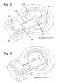
- the partition plate 12 shown in section in Fig. 2 consists of a top 12a and a Lower half 12b. In between are the slide 22, which move in a guide can, and a magnetic circuit 24.
- the transverse bore 20 of the slider 22 is opposite to Bypass hole 18 moved so that the bypass is closed here in total.
- the drive of the slider 22 is carried out electro-magnetically by means of the so-called Lorentz force.
- that of the transverse bore 20 opposite end of the Slider 22 a magnetic circuit 24 (magnetic flux ⁇ , 26) on.
- the magnetic circuit 24 (permanent magnet system) - left in Fig. 2 - consists of a Permanent magnet 28 and an iron circle 30 which forms the pole pieces and a Magnetic field (magnetic flux ⁇ , 26) generated in the area in which the rear, with a coil 32 provided part of the slider 22 is immersed with the coil (coil pocket 34, Fig. 3 and Fig. 8).
- the slider 22 is made of non-magnetic material (A1 or Plastic) and contains a coil 32 located in the coil pocket 34 of the slider 22, which is perpendicular to the part within the magnetic field 26. The return of the coil 32 must be outside the magnetic field 26 in this embodiment.
- When energizing the coil 32 acts a force in the longitudinal direction of the slider 22 perpendicular to Magnetic field 26 and perpendicular to the electric current I, 36 (right-hand rule). Becomes reversed, so sets an opposite direction of movement.
- the circular part of the partition plate halves 12a, 12b is below the GummitragMechs (rubber part, 4) attached, the angular part with the magnetic circuit 24th outside the camp 2.
- the magnetic field 26 does not have to be particularly homogeneous. It is also conceivable to be aware designed inhomogeneity in the way that the fields for the position "bypass open” and “Bypass closed” are larger than in the middle range of the movement. That could be the power to overcome the slightly higher stiction can be increased.
- the current I, 36 can be reduced to only to hold the position of the slider 22.
- the bore 20 of the Slider 22 in alignment with the bore (bypass opening 18) of the surrounding Partition plate 12 (upper and lower part of the partition plate 12a, 12b, Fig. 2).
- This can be a very streamlined bypass geometry can be realized.
- the partition plate 12 contains nor the "normal" long damping channel 14 (Fig. 2, right) and a Decoupling membrane 38, which ensures that the damping only at larger Vibration amplitudes begins.
- the problem with bypass bearings 2 is that the Decoupling membrane 38 for the bypass operation is also active and the desired effect (Reduction of dynamic stiffness) is disturbed.
Landscapes
- Engineering & Computer Science (AREA)
- General Engineering & Computer Science (AREA)
- Mechanical Engineering (AREA)
- Combined Devices Of Dampers And Springs (AREA)
- Magnetic Bearings And Hydrostatic Bearings (AREA)
- Jib Cranes (AREA)
Abstract
Description
Die Lösung mit Bohrung und Pfropfen ist nicht optimal, da der Pfropfen eine strömungsgünstige Flüssigkeitsschwingung behindert. Diese ist aber notwendig, um im Motorlager eine gute Schwingungstilgung und somit eine niedrige dynamische Steifigkeit zu bekommen.
Nachteilig ist, dass die Strömungsführung nicht verlustarm realisiert ist. Nachteilig ist auch, dass die Betätigung in Richtung der schwingenden Flüssigkeitssäule wirkt. Im geschlossenen Zustand muss also eine relativ starke Feder den Stempel gegen die Bypassbohrung drücken. Dies hat zur Folge, dass zum Öffnen der Elektromagnet gegen diese relativ starke Feder arbeiten muss, also recht stark und somit groß und teuer ausgeführt sein muss. Auch im geöffneten Zustand fließt ein hoher Strom durch die Spule, wodurch sich das Lager stark erwärmt. Durch die Anordnung der Spule mit Anker baut das Lager recht hoch. Der Anker hat zwei Endanschläge. Beim Erreichen dieser Anschläge können Geräusche entstehen.
Nachteilig ist, dass bei diesen Lösungen Vakuum benötigt wird. Von den meisten Automobilherstellern werden elektrisch betätigbare Ventileinrichtungen bevorzugt.
Zur Vakuumbetätigung wird mindestens ein Magnetventil benötigt, das Kosten verursacht und im Package des Fahrzeugs untergebracht werden muss.
Diese Art Motorlager ist recht teuer, da geringe Toleranzen eingehalten werden müssen. Die Durchführung der Welle nach außen kann Dichtprobleme bereiten. Durch die Abdichtung der sich drehenden Welle werden recht hohe Betätigungsmomente nötig. Außerdem wird generell als nachteilig angesehen, dass bei dem bekannten Verfahren Vakuum benötigt wird. Die Verlegung von Vakuumleitungen ist teuer. Bei Beschädigung des Motorlagers bzw. der Leitungen ist eine Beeinträchtigung des ebenfalls pneumatisch betätigten Bremskraftverstärkers zu befürchten.
Wenn sich in Zukunft elektrisch betätigte Bremsen ("brake by wire") durchsetzen, dann haben Dieselfahrzeuge keine Vakuumpumpe mehr, die zur Ansteuerung pneumatisch betätigter Motorlager dienen könnte.
Der apparative Aufwand für die Schaltbarkeit des Lagers erscheint unverhältnismäßig hoch. Bei einem billig hergestellten Getriebemotor ist die Zuverlässigkeit nicht gewährleistet.
Die erfindungsgemäße Antriebsart "Linearmotor" ist nicht auf einen translatorischen Schieber beschränkt sondern kann auf eine drehbar gelagerte Scheibe übertragen werden, wobei in einer Position durch zwei fluchtende Bohrungen ein Bypass geöffnet wird. Dabei befindet sich die Spule vorzugsweise auf einer Drehscheibe und macht eine Bewegung um einen gelagerten Drehpunkt.
Vorteilhafterweise wird der Magnetantrieb innerhalb des Lagers installiert.
Mit Hilfe eines inhomogenen Magnetfeldes, das die Endpositionen der Spule stärker durchflutet, kann die Haftreibung des Schiebers besser überwunden werden.
- 2
- Hydrolager, hydraulisches Motorlager
- 4
- Federelement, Gummiteil, Gummitragkörper
- 6a
- erstes) Anschlussteil
- 6b
- (zweites) Anschlussteil
- 8
- topfförmiges Gehäuse
- 8a
- zylindrische Wandung des topfförmigen Gehäuses (8)
- 8b
- Boden des topfförmigen Gehäuses (8)
- 10
- Hydraulik-Volumen
- 10a
- Arbeitskammer
- 10b
- Ausgleichskammer
- 12
- Trennplatte, Trennwand, Düsenplatte
- 12a
- obere Hälfte der Trennplatte (12)
- 12b
- untere Hälfte der Trennplatte (12)
- 14; 14a, 14b
- Drosselkanal, Dämpfungskanal
- 16
- (Roll-)Membran
- 18
- Bypass(-Öffnung), Bypass-Kanal
- 20
- Querbohrung, Bohrung
- 22
- Schieber
- 24
- Magnetkreis
- 26
- magnetischer Fluss, Magnetfeld
- 28
- Permanentmagnet
- 30
- Eisenkreis
- 32
- Spule
- 34
- Spulentasche
- 36
- elektrischer Strom I
- 38
- Entkopplungsmembran
- 40a, 40b
- Nasen, Klemmnasen
- 42
- Ausgleichsraum, Tasche(n) zur Reibungsverringerung
- 44
- schräge Nase
Claims (13)
- Bypass-schaltbares Hydrolager (2)die über mindestens einen in einer die Kammern (10a, 10b) separierenden Trennplatte (12) angeordneten Drosselkanal (14) und über einen dazu parallelgeschalteten, mittels eines elektromagnetischen Ventils verschließbaren Bypass-Kanal (18) miteinander in Verbindung stehen,insbesondere zur Verwendung als Motorlager in einem Kraftfahrzeug - mit einer Arbeitskammer (10a) und mit einer Ausgleichskammer (10b),
wobei die mit Hydraulikflüssigkeit gefüllten Volumina (10) von Arbeits- (10a) und Ausgleichskammer (10b) durch Be- und Entlastung eines Gummiteils (4) wechselweise veränderbar sind,
dadurch gekennzeichnet, dass das elektromagnetische Ventil einen mit Querbohrung (20) versehenen Schieber (22) aufweist, der durch einen mit Spule (32) versehenen Magnetkreis (24) transversal betätigbar ist,
oder dass das elektromagnetische Ventil eine um ihre vertikale Achse drehbar gelagerte, mit mindestens einer Querbohrung versehene und durch einen mit Spule versehenen Magnetkreis tangential antreibbare Scheibe aufweist,
und wobei bei Fluchten der mindestens einen Querbohrung mit der Bypass-Öffnung (18) der Bypass durchlässig ist. - Hydrolager nach Anspruch 1,
dadurch gekennzeichnet, dass der elektromagnetische Antrieb des transversal betätigbaren Schiebers (22) ein Linearantrieb ist, bei dem die Kraftwirkung auf einen stromdurchflossenen Leiter im Magnetfeld benutzt wird (Lorentzkraft). - Hydrolager nach Anspruch 1 oder 2,
dadurch gekennzeichnet, dass der Rückfluss des elektrischen Stroms I (36) mit einem entgegengesetzt gepolten Magneten in Wirkverbindung steht. - Hydrolager nach einem der Ansprüche 1 bis 3,
gekennzeichnet durch
eine Rückholfeder zur Erzeugung der Position "Bypass geschlossen" bei stromlosem Linearantrieb. - Hydrolager nach einem der Ansprüche 1 bis 4,
dadurch gekennzeichnet, dass der Magnetkreis (24) durch einen Permanentmagneten (28) oder durch einen Elektromagneten realisiert ist. - Hydrolager nach einem der Ansprüche 1 bis 5,
dadurch gekennzeichnet, dass die Bypass-Öffnung (18) eine ovale oder elliptische Querschnittsfläche aufweist. - Hydrolager nach einem der Ansprüche 1 bis 6,
dadurch gekennzeichnet, dass der Magnetantrieb innerhalb des Lagers (2) angeordnet ist. - Hydrolager nach einem der Ansprüche 1 bis 7,
dadurch gekennzeichnet, dass der Schieber (22) im Bereich der Querbohrung (20) dünner ist als im hinteren Bereich, der die Spule (32) aufnimmt. - Hydrolager nach einem der Ansprüche 1 bis 8,
dadurch gekennzeichnet, dass die Umschaltung von "Bypass geöffnet" zu "Bypass geschlossen" höherfrequent (> 100 Hz) abgestimmt ist. - Hydrolager nach einem der Ansprüche 1 bis 9,
dadurch gekennzeichnet, dass der Schieber (22) zwei schräggestellte Nasen (40a, 40b) aufweist,
mit deren Hilfe eine Entkopplungsmembran (38) in der Position "Bypass offen" eingeklemmt und somit unwirksam geschaltet wird. - Hydrolager nach einem der Ansprüche 1 bis 10,
dadurch gekennzeichnet, dass das Magnetfeld (26) zur Überwindung der Haftreibung des Schiebers (22) inhomogen gestaltet ist. - Hydrolager nach einem de Ansprüche 1 bis 11,
gekennzeichnet durch
einen Ausgleichsraum (42) neben dem Schieber (22) zur Aufnahme der verdrängten Flüssigkeit. - Hydrolager nach einem der Ansprüche 1 bis 12,
dadurch gekennzeichnet,
eine schräge Nase (44) am Ende des Schiebers (22), wodurch der Schieber (22) gegen den oberen Teil der Trennplatte (12) klemmt.
Priority Applications (3)
| Application Number | Priority Date | Filing Date | Title |
|---|---|---|---|
| EP02027114A EP1426651B1 (de) | 2002-12-04 | 2002-12-04 | Bypass-schaltbares Hydrolager |
| AT02027114T ATE360159T1 (de) | 2002-12-04 | 2002-12-04 | Bypass-schaltbares hydrolager |
| DE50209987T DE50209987D1 (de) | 2002-12-04 | 2002-12-04 | Bypass-schaltbares Hydrolager |
Applications Claiming Priority (1)
| Application Number | Priority Date | Filing Date | Title |
|---|---|---|---|
| EP02027114A EP1426651B1 (de) | 2002-12-04 | 2002-12-04 | Bypass-schaltbares Hydrolager |
Publications (2)
| Publication Number | Publication Date |
|---|---|
| EP1426651A1 true EP1426651A1 (de) | 2004-06-09 |
| EP1426651B1 EP1426651B1 (de) | 2007-04-18 |
Family
ID=32309375
Family Applications (1)
| Application Number | Title | Priority Date | Filing Date |
|---|---|---|---|
| EP02027114A Expired - Lifetime EP1426651B1 (de) | 2002-12-04 | 2002-12-04 | Bypass-schaltbares Hydrolager |
Country Status (3)
| Country | Link |
|---|---|
| EP (1) | EP1426651B1 (de) |
| AT (1) | ATE360159T1 (de) |
| DE (1) | DE50209987D1 (de) |
Cited By (4)
| Publication number | Priority date | Publication date | Assignee | Title |
|---|---|---|---|---|
| WO2006136233A1 (de) * | 2005-06-18 | 2006-12-28 | Contitech Vibration Control Gmbh | Hydrolager mit elektrisch schaltbarem bypass |
| DE102009059234A1 (de) | 2009-12-21 | 2011-06-22 | ContiTech Vibration Control GmbH, 30453 | Adaptives Motorlager |
| DE102014224244A1 (de) * | 2014-11-27 | 2016-06-02 | Contitech Vibration Control Gmbh | Hydrolager sowie Kraftfahrzeug mit einem derartigen Hydrolager |
| DE102016110703A1 (de) * | 2016-06-10 | 2017-12-14 | Vibracoustic Gmbh | Hydrolager |
Citations (7)
| Publication number | Priority date | Publication date | Assignee | Title |
|---|---|---|---|---|
| DE3316025C2 (de) | 1983-05-03 | 1988-09-29 | Tillmann 6108 Weiterstadt De Freudenberg | |
| US4783062A (en) * | 1987-07-01 | 1988-11-08 | General Motors Corporation | Electronic hydraulic mount-internal solenoid |
| US4796874A (en) * | 1987-10-02 | 1989-01-10 | General Motors Corporation | Electronic hydraulic mount with continuously variable control |
| US5246213A (en) * | 1992-11-24 | 1993-09-21 | General Motors Corporation | Hydraulic mount for improved idle and high frequency isolation |
| GB2278660A (en) | 1993-05-26 | 1994-12-07 | Honda Motor Co Ltd | Liquid-elastomer vibration-isolating device |
| DE19902493A1 (de) | 1999-01-22 | 2000-07-27 | Freudenberg Carl Fa | Umschaltbares Zweikammer-Stützlager mit hydraulischer Dämpfung |
| DE19807868C2 (de) | 1998-02-25 | 2001-06-28 | Freudenberg Carl Fa | Hydraulisch dämpfendes Lager |
-
2002
- 2002-12-04 AT AT02027114T patent/ATE360159T1/de not_active IP Right Cessation
- 2002-12-04 DE DE50209987T patent/DE50209987D1/de not_active Expired - Lifetime
- 2002-12-04 EP EP02027114A patent/EP1426651B1/de not_active Expired - Lifetime
Patent Citations (8)
| Publication number | Priority date | Publication date | Assignee | Title |
|---|---|---|---|---|
| DE3316025C2 (de) | 1983-05-03 | 1988-09-29 | Tillmann 6108 Weiterstadt De Freudenberg | |
| US4783062A (en) * | 1987-07-01 | 1988-11-08 | General Motors Corporation | Electronic hydraulic mount-internal solenoid |
| US4796874A (en) * | 1987-10-02 | 1989-01-10 | General Motors Corporation | Electronic hydraulic mount with continuously variable control |
| US5246213A (en) * | 1992-11-24 | 1993-09-21 | General Motors Corporation | Hydraulic mount for improved idle and high frequency isolation |
| GB2278660A (en) | 1993-05-26 | 1994-12-07 | Honda Motor Co Ltd | Liquid-elastomer vibration-isolating device |
| DE19807868C2 (de) | 1998-02-25 | 2001-06-28 | Freudenberg Carl Fa | Hydraulisch dämpfendes Lager |
| DE19902493A1 (de) | 1999-01-22 | 2000-07-27 | Freudenberg Carl Fa | Umschaltbares Zweikammer-Stützlager mit hydraulischer Dämpfung |
| DE19902493C2 (de) | 1999-01-22 | 2001-02-01 | Freudenberg Carl Fa | Umschaltbares Zweikammer-Stützlager mit hydraulischer Dämpfung |
Cited By (14)
| Publication number | Priority date | Publication date | Assignee | Title |
|---|---|---|---|---|
| JP4782195B2 (ja) * | 2005-06-18 | 2011-09-28 | コンティテク・バイブレーション・コントロール・ゲゼルシャフト・ミト・ベシュレンクテル・ハフツング | 電気的に切換え可能なバイパスを備えた液体封入マウント |
| JP2008544178A (ja) * | 2005-06-18 | 2008-12-04 | コンティテク・バイブレーション・コントロール・ゲゼルシャフト・ミト・ベシュレンクテル・ハフツング | 電気的に切換え可能なバイパスを備えた液体封入マウント |
| DE102005028337B4 (de) * | 2005-06-18 | 2014-03-20 | Contitech Vibration Control Gmbh | Hydrolager mit elektrisch schaltbarem Bypass |
| WO2006136233A1 (de) * | 2005-06-18 | 2006-12-28 | Contitech Vibration Control Gmbh | Hydrolager mit elektrisch schaltbarem bypass |
| US8616537B2 (en) | 2009-12-21 | 2013-12-31 | Contitech Vibration Control Gmbh | Adaptive motor mount |
| CN102792051A (zh) * | 2009-12-21 | 2012-11-21 | 康蒂泰克振动控制有限公司 | 自适应发动机轴承 |
| WO2011076455A1 (de) | 2009-12-21 | 2011-06-30 | Contitech Vibration Control Gmbh | Adaptives motorlager |
| DE102009059234A1 (de) | 2009-12-21 | 2011-06-22 | ContiTech Vibration Control GmbH, 30453 | Adaptives Motorlager |
| CN102792051B (zh) * | 2009-12-21 | 2014-08-27 | 康蒂泰克振动控制有限公司 | 自适应发动机轴承 |
| DE102009059234B4 (de) | 2009-12-21 | 2020-08-06 | Contitech Vibration Control Gmbh | Adaptives Motorlager |
| DE102014224244A1 (de) * | 2014-11-27 | 2016-06-02 | Contitech Vibration Control Gmbh | Hydrolager sowie Kraftfahrzeug mit einem derartigen Hydrolager |
| DE102016110703A1 (de) * | 2016-06-10 | 2017-12-14 | Vibracoustic Gmbh | Hydrolager |
| WO2017211507A1 (de) * | 2016-06-10 | 2017-12-14 | Vibracoustic Gmbh | Hydrolager |
| CN109073034A (zh) * | 2016-06-10 | 2018-12-21 | 威巴克公司 | 液压支承 |
Also Published As
| Publication number | Publication date |
|---|---|
| DE50209987D1 (de) | 2007-05-31 |
| EP1426651B1 (de) | 2007-04-18 |
| ATE360159T1 (de) | 2007-05-15 |
Similar Documents
| Publication | Publication Date | Title |
|---|---|---|
| EP0401463B1 (de) | Gummilager mit hydraulischer Dämpfung | |
| DE69908467T2 (de) | Flüssigkeitsgefüllte, aktive schwingungsdämpfende Vorrichtung mit einem oszillierenden, durch Impulssignale gesteuerten Bauteil | |
| DE3827255C2 (de) | Regelbarer hydraulischer Schwingungsdämpfer für Kraftfahrzeuge | |
| DE3542917A1 (de) | Montageeinheit fuer einen antrieb | |
| EP3209530A1 (de) | Kippankerventil für eine bremse eines fahrzeugs und verfahren zum betreiben eines kippankerventils | |
| WO2014122312A1 (de) | Linearaktuator | |
| EP0664854B1 (de) | Kraftstoffeinspritzvorrichtung für brennkraftmaschinen | |
| EP1426651B1 (de) | Bypass-schaltbares Hydrolager | |
| DE2330943C3 (de) | Elektromagnetisch betätigbarer Hydraulikschalter | |
| EP1972826B1 (de) | Hydrolager | |
| EP0541902B1 (de) | Gummilager | |
| DE3633312C2 (de) | ||
| DE2658969A1 (de) | Druckregelventil | |
| DE4109181A1 (de) | Stossdaempfer mit veraenderlicher daempfungskraft | |
| DE102020213592A1 (de) | Frequenzselektive Dämpfventilanordnung | |
| DE4002883A1 (de) | Schwingungsdaempfersteuerventil eines bypasses mit selbsthaltung | |
| DE3526191A1 (de) | Druckmodulator | |
| DE10229774C1 (de) | Motorlager mit schaltbarem Bypass | |
| WO2008043630A1 (de) | Luftfeder- und dämpfereinheit | |
| DE2022547A1 (de) | Motor mit schwingenden Antriebselementen | |
| EP0248229B1 (de) | Bremsgerät für eine hydraulische Fahrzeugbremsanlage | |
| DE19833458A1 (de) | Motorlager | |
| WO2006136233A1 (de) | Hydrolager mit elektrisch schaltbarem bypass | |
| EP1457722B1 (de) | Anbausatz für ein Fahrzeug-Luftfedersystem mit einem zuschaltbaren Zusatz-Luftfedervolumen | |
| WO2007014827A1 (de) | Hydraulikventil |
Legal Events
| Date | Code | Title | Description |
|---|---|---|---|
| PUAI | Public reference made under article 153(3) epc to a published international application that has entered the european phase |
Free format text: ORIGINAL CODE: 0009012 |
|
| AK | Designated contracting states |
Kind code of ref document: A1 Designated state(s): AT BE BG CH CY CZ DE DK EE ES FI FR GB GR IE IT LI LU MC NL PT SE SI SK TR |
|
| AX | Request for extension of the european patent |
Extension state: AL LT LV MK RO |
|
| 17P | Request for examination filed |
Effective date: 20041209 |
|
| AKX | Designation fees paid |
Designated state(s): AT BE BG CH CY CZ DE DK EE ES FI FR GB GR IE IT LI LU MC NL PT SE SI SK TR |
|
| 17Q | First examination report despatched |
Effective date: 20050503 |
|
| GRAP | Despatch of communication of intention to grant a patent |
Free format text: ORIGINAL CODE: EPIDOSNIGR1 |
|
| GRAS | Grant fee paid |
Free format text: ORIGINAL CODE: EPIDOSNIGR3 |
|
| GRAA | (expected) grant |
Free format text: ORIGINAL CODE: 0009210 |
|
| AK | Designated contracting states |
Kind code of ref document: B1 Designated state(s): AT BE BG CH CY CZ DE DK EE ES FI FR GB GR IE IT LI LU MC NL PT SE SI SK TR |
|
| PG25 | Lapsed in a contracting state [announced via postgrant information from national office to epo] |
Ref country code: FI Free format text: LAPSE BECAUSE OF FAILURE TO SUBMIT A TRANSLATION OF THE DESCRIPTION OR TO PAY THE FEE WITHIN THE PRESCRIBED TIME-LIMIT Effective date: 20070418 Ref country code: SI Free format text: LAPSE BECAUSE OF FAILURE TO SUBMIT A TRANSLATION OF THE DESCRIPTION OR TO PAY THE FEE WITHIN THE PRESCRIBED TIME-LIMIT Effective date: 20070418 |
|
| REG | Reference to a national code |
Ref country code: CH Ref legal event code: EP |
|
| REG | Reference to a national code |
Ref country code: IE Ref legal event code: FG4D Free format text: LANGUAGE OF EP DOCUMENT: GERMAN |
|
| REF | Corresponds to: |
Ref document number: 50209987 Country of ref document: DE Date of ref document: 20070531 Kind code of ref document: P |
|
| PG25 | Lapsed in a contracting state [announced via postgrant information from national office to epo] |
Ref country code: SE Free format text: LAPSE BECAUSE OF FAILURE TO SUBMIT A TRANSLATION OF THE DESCRIPTION OR TO PAY THE FEE WITHIN THE PRESCRIBED TIME-LIMIT Effective date: 20070718 |
|
| PG25 | Lapsed in a contracting state [announced via postgrant information from national office to epo] |
Ref country code: ES Free format text: LAPSE BECAUSE OF FAILURE TO SUBMIT A TRANSLATION OF THE DESCRIPTION OR TO PAY THE FEE WITHIN THE PRESCRIBED TIME-LIMIT Effective date: 20070729 |
|
| PG25 | Lapsed in a contracting state [announced via postgrant information from national office to epo] |
Ref country code: PT Free format text: LAPSE BECAUSE OF FAILURE TO SUBMIT A TRANSLATION OF THE DESCRIPTION OR TO PAY THE FEE WITHIN THE PRESCRIBED TIME-LIMIT Effective date: 20070918 |
|
| NLV1 | Nl: lapsed or annulled due to failure to fulfill the requirements of art. 29p and 29m of the patents act | ||
| GBV | Gb: ep patent (uk) treated as always having been void in accordance with gb section 77(7)/1977 [no translation filed] |
Effective date: 20070418 |
|
| REG | Reference to a national code |
Ref country code: IE Ref legal event code: FD4D |
|
| EN | Fr: translation not filed | ||
| PG25 | Lapsed in a contracting state [announced via postgrant information from national office to epo] |
Ref country code: NL Free format text: LAPSE BECAUSE OF FAILURE TO SUBMIT A TRANSLATION OF THE DESCRIPTION OR TO PAY THE FEE WITHIN THE PRESCRIBED TIME-LIMIT Effective date: 20070418 Ref country code: DK Free format text: LAPSE BECAUSE OF FAILURE TO SUBMIT A TRANSLATION OF THE DESCRIPTION OR TO PAY THE FEE WITHIN THE PRESCRIBED TIME-LIMIT Effective date: 20070418 Ref country code: IE Free format text: LAPSE BECAUSE OF FAILURE TO SUBMIT A TRANSLATION OF THE DESCRIPTION OR TO PAY THE FEE WITHIN THE PRESCRIBED TIME-LIMIT Effective date: 20070418 Ref country code: CZ Free format text: LAPSE BECAUSE OF FAILURE TO SUBMIT A TRANSLATION OF THE DESCRIPTION OR TO PAY THE FEE WITHIN THE PRESCRIBED TIME-LIMIT Effective date: 20070418 Ref country code: BG Free format text: LAPSE BECAUSE OF FAILURE TO SUBMIT A TRANSLATION OF THE DESCRIPTION OR TO PAY THE FEE WITHIN THE PRESCRIBED TIME-LIMIT Effective date: 20070718 |
|
| PLBE | No opposition filed within time limit |
Free format text: ORIGINAL CODE: 0009261 |
|
| STAA | Information on the status of an ep patent application or granted ep patent |
Free format text: STATUS: NO OPPOSITION FILED WITHIN TIME LIMIT |
|
| PG25 | Lapsed in a contracting state [announced via postgrant information from national office to epo] |
Ref country code: SK Free format text: LAPSE BECAUSE OF FAILURE TO SUBMIT A TRANSLATION OF THE DESCRIPTION OR TO PAY THE FEE WITHIN THE PRESCRIBED TIME-LIMIT Effective date: 20070418 |
|
| 26N | No opposition filed |
Effective date: 20080121 |
|
| PG25 | Lapsed in a contracting state [announced via postgrant information from national office to epo] |
Ref country code: FR Free format text: LAPSE BECAUSE OF FAILURE TO SUBMIT A TRANSLATION OF THE DESCRIPTION OR TO PAY THE FEE WITHIN THE PRESCRIBED TIME-LIMIT Effective date: 20071214 Ref country code: IT Free format text: LAPSE BECAUSE OF FAILURE TO SUBMIT A TRANSLATION OF THE DESCRIPTION OR TO PAY THE FEE WITHIN THE PRESCRIBED TIME-LIMIT Effective date: 20070418 Ref country code: GB Free format text: LAPSE BECAUSE OF FAILURE TO SUBMIT A TRANSLATION OF THE DESCRIPTION OR TO PAY THE FEE WITHIN THE PRESCRIBED TIME-LIMIT Effective date: 20070418 Ref country code: GR Free format text: LAPSE BECAUSE OF FAILURE TO SUBMIT A TRANSLATION OF THE DESCRIPTION OR TO PAY THE FEE WITHIN THE PRESCRIBED TIME-LIMIT Effective date: 20070719 |
|
| BERE | Be: lapsed |
Owner name: CONTITECH VIBRATION CONTROL G.M.B.H. Effective date: 20071231 |
|
| PG25 | Lapsed in a contracting state [announced via postgrant information from national office to epo] |
Ref country code: MC Free format text: LAPSE BECAUSE OF NON-PAYMENT OF DUE FEES Effective date: 20071231 |
|
| REG | Reference to a national code |
Ref country code: CH Ref legal event code: PL |
|
| PG25 | Lapsed in a contracting state [announced via postgrant information from national office to epo] |
Ref country code: BE Free format text: LAPSE BECAUSE OF NON-PAYMENT OF DUE FEES Effective date: 20071231 |
|
| PG25 | Lapsed in a contracting state [announced via postgrant information from national office to epo] |
Ref country code: LI Free format text: LAPSE BECAUSE OF NON-PAYMENT OF DUE FEES Effective date: 20071231 Ref country code: CH Free format text: LAPSE BECAUSE OF NON-PAYMENT OF DUE FEES Effective date: 20071231 |
|
| PG25 | Lapsed in a contracting state [announced via postgrant information from national office to epo] |
Ref country code: FR Free format text: LAPSE BECAUSE OF FAILURE TO SUBMIT A TRANSLATION OF THE DESCRIPTION OR TO PAY THE FEE WITHIN THE PRESCRIBED TIME-LIMIT Effective date: 20070418 |
|
| PG25 | Lapsed in a contracting state [announced via postgrant information from national office to epo] |
Ref country code: EE Free format text: LAPSE BECAUSE OF FAILURE TO SUBMIT A TRANSLATION OF THE DESCRIPTION OR TO PAY THE FEE WITHIN THE PRESCRIBED TIME-LIMIT Effective date: 20070418 |
|
| PG25 | Lapsed in a contracting state [announced via postgrant information from national office to epo] |
Ref country code: AT Free format text: LAPSE BECAUSE OF NON-PAYMENT OF DUE FEES Effective date: 20071204 |
|
| PG25 | Lapsed in a contracting state [announced via postgrant information from national office to epo] |
Ref country code: CY Free format text: LAPSE BECAUSE OF FAILURE TO SUBMIT A TRANSLATION OF THE DESCRIPTION OR TO PAY THE FEE WITHIN THE PRESCRIBED TIME-LIMIT Effective date: 20070418 |
|
| PG25 | Lapsed in a contracting state [announced via postgrant information from national office to epo] |
Ref country code: LU Free format text: LAPSE BECAUSE OF NON-PAYMENT OF DUE FEES Effective date: 20071204 |
|
| PG25 | Lapsed in a contracting state [announced via postgrant information from national office to epo] |
Ref country code: TR Free format text: LAPSE BECAUSE OF FAILURE TO SUBMIT A TRANSLATION OF THE DESCRIPTION OR TO PAY THE FEE WITHIN THE PRESCRIBED TIME-LIMIT Effective date: 20070418 |
|
| REG | Reference to a national code |
Ref country code: DE Ref legal event code: R231 Ref document number: 50209987 Country of ref document: DE |
|
| PG25 | Lapsed in a contracting state [announced via postgrant information from national office to epo] |
Ref country code: DE Free format text: LAPSE BECAUSE OF THE APPLICANT RENOUNCES Effective date: 20160330 |
|
| PGFP | Annual fee paid to national office [announced via postgrant information from national office to epo] |
Ref country code: DE Payment date: 20151231 Year of fee payment: 14 |