EP1426989B1 - Outil à main à moteur électrique - Google Patents
Outil à main à moteur électrique Download PDFInfo
- Publication number
- EP1426989B1 EP1426989B1 EP03025863A EP03025863A EP1426989B1 EP 1426989 B1 EP1426989 B1 EP 1426989B1 EP 03025863 A EP03025863 A EP 03025863A EP 03025863 A EP03025863 A EP 03025863A EP 1426989 B1 EP1426989 B1 EP 1426989B1
- Authority
- EP
- European Patent Office
- Prior art keywords
- tool
- housing
- motor
- actuator
- linkage
- Prior art date
- Legal status (The legal status is an assumption and is not a legal conclusion. Google has not performed a legal analysis and makes no representation as to the accuracy of the status listed.)
- Expired - Lifetime
Links
- 238000005553 drilling Methods 0.000 abstract description 3
- 230000000994 depressogenic effect Effects 0.000 description 7
- 230000007246 mechanism Effects 0.000 description 6
- 230000002093 peripheral effect Effects 0.000 description 2
- 210000003811 finger Anatomy 0.000 description 1
- 210000005224 forefinger Anatomy 0.000 description 1
- 230000010354 integration Effects 0.000 description 1
Images


Classifications
-
- H—ELECTRICITY
- H02—GENERATION; CONVERSION OR DISTRIBUTION OF ELECTRIC POWER
- H02K—DYNAMO-ELECTRIC MACHINES
- H02K23/00—DC commutator motors or generators having mechanical commutator; Universal AC/DC commutator motors
- H02K23/66—Structural association with auxiliary electric devices influencing the characteristic of, or controlling, the machine, e.g. with impedances or switches
-
- B—PERFORMING OPERATIONS; TRANSPORTING
- B25—HAND TOOLS; PORTABLE POWER-DRIVEN TOOLS; MANIPULATORS
- B25F—COMBINATION OR MULTI-PURPOSE TOOLS NOT OTHERWISE PROVIDED FOR; DETAILS OR COMPONENTS OF PORTABLE POWER-DRIVEN TOOLS NOT PARTICULARLY RELATED TO THE OPERATIONS PERFORMED AND NOT OTHERWISE PROVIDED FOR
- B25F5/00—Details or components of portable power-driven tools not particularly related to the operations performed and not otherwise provided for
- B25F5/001—Gearings, speed selectors, clutches or the like specially adapted for rotary tools
-
- B—PERFORMING OPERATIONS; TRANSPORTING
- B25—HAND TOOLS; PORTABLE POWER-DRIVEN TOOLS; MANIPULATORS
- B25F—COMBINATION OR MULTI-PURPOSE TOOLS NOT OTHERWISE PROVIDED FOR; DETAILS OR COMPONENTS OF PORTABLE POWER-DRIVEN TOOLS NOT PARTICULARLY RELATED TO THE OPERATIONS PERFORMED AND NOT OTHERWISE PROVIDED FOR
- B25F5/00—Details or components of portable power-driven tools not particularly related to the operations performed and not otherwise provided for
- B25F5/02—Construction of casings, bodies or handles
-
- H—ELECTRICITY
- H01—ELECTRIC ELEMENTS
- H01H—ELECTRIC SWITCHES; RELAYS; SELECTORS; EMERGENCY PROTECTIVE DEVICES
- H01H9/00—Details of switching devices, not covered by groups H01H1/00 - H01H7/00
- H01H9/02—Bases, casings, or covers
- H01H9/06—Casing of switch constituted by a handle serving a purpose other than the actuation of the switch, e.g. by the handle of a vacuum cleaner
- H01H9/063—Casing of switch constituted by a handle serving a purpose other than the actuation of the switch, e.g. by the handle of a vacuum cleaner enclosing a reversing switch
-
- H—ELECTRICITY
- H02—GENERATION; CONVERSION OR DISTRIBUTION OF ELECTRIC POWER
- H02K—DYNAMO-ELECTRIC MACHINES
- H02K7/00—Arrangements for handling mechanical energy structurally associated with dynamo-electric machines, e.g. structural association with mechanical driving motors or auxiliary dynamo-electric machines
- H02K7/14—Structural association with mechanical loads, e.g. with hand-held machine tools or fans
- H02K7/145—Hand-held machine tool
Definitions
- the invention relates to an electric motor driven hand-held tool, such as a hammering, drilling and/or screwdriving tool, having a main switch which is actuated to actuate the motor and a forward/reverse switch which is actuated to select the desired direction of rotation of the motor.
- the main switch and the forward/reverse switch are conveniently combined in a single integrated switch unit.
- Such integrated switch units generally includes a first actuator which is actuated via a trigger switch, which trigger switch is depressed by a user to turn the motor on and released to turn the motor off. Generally the speed of the motor can also be controlled depending on the extent that the trigger switch and thus the first actuator is depressed.
- An electronic control unit is generally incorporated within the integrated switch unit, and is responsive to the first actuator to apply the appropriate current to the motor.
- the integrated switch unit will also generally include a second actuator which can be moved between two positions via a forward/reverse lever moveable by a user.
- the electronic control unit is also generally responsive to the second actuator and in a first forward position of the second actuator the electronic control unit will drive the motor in a forward direction of rotation and in a second reverse position of the second actuator the electronic control unit will drive the motor in a second reverse direction.
- the main switch and the forward/reverse switch are generally mechanically coupled, so that the position of the forward/reverse switch can only be changed to alter the direction of rotation when the main switch is released, i.e. when the motor is switched off.
- a mechanical interface in the form of a slideable locking bar, is moved into the path of the trigger switch of the main switch by movement of the forward/reverse switch between the forward and reverse position or vice versa.
- the mechanical interface is arranged so that when the trigger switch is depressed the trigger switch blocks movement of the locking bar and so prevents movement of the forward/reverse switch between its two positions.
- US 4523116 discloses an electrical connection system for motors in which actuation of a forward/reverse mechanism of a power tool is prevented when the motor of the tool is operated in order to avoid damage to the motor.
- the present invention aims to provide a tool with a combined main and forward/reverse switch arrangement which is suitable for use with an integrated switch unit of the type described above and which enables a user to see the forward/reverse switch lever in most normal operating positions of the tool.
- an electric motor driven hand-held tool having a tool housing, a motor, a first actuator which is actuated by a manually operable power member, a second actuator which is actuated by a manually operable forward/reverse member wherein the forward/reverse member is located on a portion of the tool housing which can be seen by a user of the tool during normal operation of the tool, and a linkage arrangement moveably mounted within the tool housing for actuating the second actuator in response to a manual actuation of the forward/reverse member, characterised by an integrated switch unit located within the tool housing and including an electronic motor control unit, said first actuator and said second actuator, wherein the control unit is responsive to said first actuator to power the motor and is responsive to said second actuator to drive the motor in a selected forward or reverse direction, and wherein said forward/reverse member is located remotely from the switch unit.
- a linkage enables the forward/reverse switch to be located on an easily viewable location on the tool housing, while still enabling the use of
- the forward/reverse member may be located on a surface of the tool housing which is directed upwardly in the most common operating position of the tool.
- the forward/reverse member may be located towards the rearward end of said surface of the tool housing so as to be close to the user.
- the forward/reverse lever may be located on a rearward facing surface of the tool housing which faces towards the user during normal operation of the tool.
- the tool which may for example be a drilling, hammering or screw driving tool may have a housing which has a body portion and a main handle extending from the body portion.
- the forward reverse member may be conveniently located on the body portion and the power member may be located on the main handle with the switch unit located adjacent the power member. This enables the power member to be actuated by a finger of a hand of a user who is gripping the main handle.
- the body portion is generally more easily viewed by a user, than the handle portion, during use of the tool.
- the forward reverse member may be located, for easy viewing, on an upper facing face of the tool housing (in the normal operating position of the hammer) and the power member may be located on a downwardly facing face of the tool housing with the switch unit located adjacent the power member.
- the linkage is pivotally mounted within the tool housing so that manual actuation of the forward/reverse member causes the linkage to pivot and to actuate the second actuator.
- the linkage could be slideably mounted within the tool housing.
- the linkage may be pivotally mounted on a motor housing portion of the tool housing, for example on a closed end of the motor housing, which motor housing end is adjacent to an end of the motor.
- the closed end of the motor housing may be the rearward end of the motor housing. This provides an easily manufactured and assembled arrangement where the motor housing is a jam pot housing having said closed end and an opposite open end.
- the pivot axis of the linkage may be parallel to the longitudinal axis of the motor.
- the pivotally mounted portion of the linkage may be formed with a central annular portion which is pivotable about a boss formed on the closed end of the motor housing.
- a first arm may extend from the pivotally mounted portion of the linkage and the forward/reverse member may be located on this first arm.
- a second arm may extend from the pivotally mounted portion of the linkage and the second arm engages the second actuator.
- a fixing boss may extend from the motor housing and a rear handle portion of the tool housing may be fixed to the motor housing via a fixing which engages the fixing boss and the fixing boss may be made engageable with the linkage to limit movement of the linkage within the tool housing.
- the hammers shown in Figures 1 to 4 have a housing comprising a rear handle housing (2) and a body portion comprising a motor housing (3) and a gear housing (5).
- the rear handle housing (2) can be fitted to the downward extension of the motor housing (3) to form the downwardly extending main handle of the hammer, which is a pistol grip style handle.
- the motor housing (3) houses a motor (150) (the outline of which is shown in dotted lines in Figure 4) of the hammer and is of a jam pot design with an open forward end and a closed rearward end, so that the motor is inserted into the motor housing (3) from the front.
- the motor is mounted in the jam pot motor housing (3) with its longitudinal axis (7) (shown in dotted lines in Figure 4) extending parallel to the longitudinal axis of a tool or bit (11) when such a tool or bit is mounted in the tool holder (9) of the hammer.
- a tool or bit mounted within the tool holder of the hammer will receive repeated impacts from a hammering mechanism of the hammer and/or will be rotatingly driven by a rotary drive mechanism of the hammer, depending on the mode of operation of the hammer selected by a user.
- the motor drives the hammering mechanism and the rotary drive mechanism of the hammer.
- Such hammering and rotary drive mechanisms are well known in the art.
- the handle could be a D-shaped handle extending rearwardly from the body portion (3, 5) or where the hammer is an L-shaped hammer with the motor mounted perpendicular to the axis of the tool or bit the handle the handle could be a D-handle extending rearwardly of the motor housing of the hammer.
- the hammers shown in Figures 1 to 4 comprise a main switch and a forward/reverse switch which are combined in a single integrated switch unit (6).
- Such integrated switch units generally includes a first actuator (not shown) which is actuated via a trigger switch (4).
- the trigger switch (4) is located, in a conventional position for pistol grip style handles, at the interface between the front of the rear handle (2) of the hammer and the underside of the body portion (3, 5) of the hammer, so that it can be actuated by a fore finger of a user who is grasping the rear handle.
- the trigger switch (4) is depressed by a user to turn the motor on and released to turn the motor off.
- the speed of the motor can be controlled depending on the extent that the trigger switch (4) and thus the first actuator is depressed.
- the switch unit (6) is located within the main handle adjacent the trigger switch (4).
- An electronic control unit (8) is incorporated within the integrated switch unit (6) and is electrically connected to the motor of the hammer.
- the electronic control unit (8) is responsive to the first actuator to apply the appropriate current to the motor.
- the integrated switch (6) unit also includes a second actuator (10) which can be moved between two positions via a forward/reverse lever moveable by a user.
- the electronic control unit (8) is also responsive to the second actuator (10) which is moveable in a direction indicated by the arrows in Figure 3A. In a first forward position of the second actuator the electronic control unit will drive the motor in a forward direction of rotation and in a second rearward position of the second actuator the electronic control unit will drive the motor in a second reverse direction.
- the prior art hammer, shown in Figure 1 is provided with an integrated switch unit (6) and the second actuator (10) is moved between its forward and reverse position by a switch lever (21).
- the switch lever (21) has a central portion which engages the second actuator (10).
- the lever (21) is slideably mounted within the motor housing (3) so as to slide laterally and is mounted in the motor housing with its ends extending laterally beyond the outer surface of the motor housing. When a first end of the lever (21), which can be seen in Figure 1, is pushed towards the hammer housing (3) the second actuator (10) is moved to its reverse position.
- the integrated switch unit (6) used in the hammers of Figures 1 to 4 is arranged so that the second actuator (10) cannot be moved between its forward and reverse positions while the trigger switch (4) is depressed, i.e. while the motor is running.
- a wall (12) is formed within the trigger switch (4) so that in the forward position of the second actuator (10), a depending portion (10b) of the second actuator (10) is located to the left hand side of the wall (12) (see position in Figure 3). In the reverse position of the second actuator (10), the depending portion (10b) of the second actuator is located to the right hand side of the wall (12).
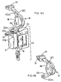
- FIG. 2 to 4 An improved forward/reverse switch arrangement, according to the present invention is shown in Figures 2 to 4.
- the forward/reverse lever (14) which is actuated by a user is located on the upper part of the motor housing (3) (i.e. the part of the housing which is directed upwardly in the most common operating position of the hammer) some distance above the trigger switch (4), as shown in Figures 2 and 4.
- a linkage (16) is required to actuate the second actuator (10) of the integrated switch unit (6).
- the linkage (16) has an annular central portion (18) and an upwardly extending arm (20) with the forward/reverse lever (14) located at the end of the upwardly extending arm remote from the annular portion (18).
- the linkage (16) also has a downwardly extending arm (22) which incorporates a through hole (22a) for receiving a pin (10a) formed on the second actuator (10) of the integrated switch unit (6).
- the annular portion (18) of the linkage (16) is pivotally mounted around the periphery of a circular boss (24) which boss is formed on the rearward closed end of the motor housing (3).
- the linkage (16) is arranged to pivot about an axis (7) which is parallel to the longitudinal axis of the motor.
- a rear handle housing part (2) is fitted to the rear of the motor housing (3) so that a peripheral rim at the forward edge of the rear handle housing (2) abuts a peripheral rim (26) at the rearward edge of the motor housing (3) (See Figure 2).
- the rear handle housing has a portion (not shown) which abuts the boss (24) in order to secure the annular portion (18) of the linkage (16) pivotally around the boss (24).
- the rear handle housing (2) has a recess (30) in the forward edge of its upper portion which mates with the rearward edge (15) of the upper portion of the motor housing (3) to form a hole in the hammer housing through which the forward/reverse lever (14) extends.
- the forward/reverse lever (14) is located on an a rearward part of an upper face of the hammer housing in the normal operating position of the hammer.
- the upwardly extending arm (20) of the linkage (16) is formed with a through hole (20a) through which a screw boss (34) extends rearwardly from the motor housing (3).
- the screw boss (34) is engageable with the edges of the through hole (20a) in the arm (20) so as to limit the extent of the pivotal movement of the linkage (16).
- a screw which extends through the rear handle housing (2) is secured within the screw boss (34) so as to fix the rear handle housing (2) to the motor housing (3).
- the forward/reverse lever (14) can be moved by a user to the desired forward or reverse position. This causes the linkage (16) to pivot about the boss (24) to cause the lower arm (22) to move the second actuator (10) to the desired forward or reverse position.
- the forward facing edge of the forward/reverse lever (14) may be formed with a small projection (13) which is selectively engageable, in a snap fit with one of a corresponding pair of recesses formed in the rearward facing edge (15) of the motor housing (3) adjacent the lever (14).
- the projection resiliently engages one of the recesses in a snap fit in the forward position of the lever (14) and the other of the recesses in the reverse position of the lever (14).
Landscapes
- Engineering & Computer Science (AREA)
- Mechanical Engineering (AREA)
- Power Engineering (AREA)
- Drilling And Boring (AREA)
- Portable Power Tools In General (AREA)
- Percussive Tools And Related Accessories (AREA)
- Iron Core Of Rotating Electric Machines (AREA)
- Manipulator (AREA)
Claims (16)
- Outil à main entraîné par un moteur électrique comprenant un carter d'outil (2, 3), un moteur (150), un premier actionneur qui est actionné par un élément de commande électrique actionnable manuellement (4), un deuxième actionneur (10) qui est actionné par un élément de commande en marche avant / en marche arrière actionnable manuellement (14), dans lequel l'élément de commande en marche avant / en marche arrière est placé sur une partie du carter d'outil qui peut être vue par un utilisateur de l'outil durant un fonctionnement normal de l'outil, et un dispositif de raccordement (16) monté de façon mobile à l'intérieur du carter d'outil pour actionner le deuxième actionneur en réponse à un actionnement manuel de l'élément de commande en marche avant / en marche arrière, caractérisé par une unité de commutation intégrée (6) disposée à l'intérieur du carter d'outil et comprenant une unité de commande de moteur électronique (8), ledit premier actionneur et ledit deuxième actionneur, dans lequel l'unité de commande répond au dit premier actionneur pour alimenter électriquement le moteur et répond au dit deuxième actionneur pour commander le moteur dans une direction sélectionnée en marche avant ou en marche arrière, et dans lequel ledit élément de commande en marche avant / en marche arrière est placé à distance par rapport à l'unité de commutation.
- Outil selon la revendication 1, dans lequel l'élément de commande en marche avant / en marche arrière (14) est placé sur une surface du carter d'outil qui est dirigée vers le haut dans la position d'utilisation la plus courante de l'outil.
- Outil selon la revendication 1 ou 2, dans lequel le carter d'outil comprend une partie de corps (3, 5) ainsi qu'une poignée principale (2) s'étendant depuis la partie de corps, et l'élément de commande en marche avant / en marche arrière (14) est placé sur la partie de corps (3, 5), et l'élément de commande électrique (4) est placé sur la poignée principale avec l'unité de commutation (6) disposée adjacente à l'élément de commande électrique (4).
- Outil selon l'une quelconque des revendications précédentes, dans lequel l'élément de commande en marche avant / en marche arrière (14) est placé sur une face dirigée vers le haut du carter d'outil dans la position d'utilisation normale de l'outil, et l'élément de commande électrique (4) est placé sur une face dirigée vers le bas du carter d'outil avec l'unité de commutation (6) disposée adjacente à l'élément de commande électrique.
- Outil selon l'une quelconque des revendications précédentes, dans lequel le dispositif de raccordement (16) est monté de manière pivotante à l'intérieur du carter d'outil, de sorte qu'un actionnement manuel de l'élément de commande en marche avant / en marche arrière (14) amène le dispositif de raccordement à pivoter et à actionner le deuxième actionneur (10).
- Outil selon la revendication 5, dans lequel le dispositif de raccordement (16) est monté de manière pivotante sur une partie de carter moteur (3) du carter d'outil.
- Outil selon la revendication 6, dans lequel le dispositif de raccordement (16) est monté de manière pivotante sur une extrémité fermée du carter moteur (3), laquelle extrémité du carter moteur est adjacente à une extrémité du moteur.
- Outil selon la revendication 7, dans lequel l'extrémité fermée du carter moteur (3) correspond à l'extrémité arrière du carter moteur.
- Outil selon l'une quelconque des revendications 6 à 8, dans lequel l'axe de pivot du dispositif de raccordement (16) est parallèle à l'axe longitudinal du moteur.
- Outil selon l'une quelconque des revendications 7 à 9, dans lequel la partie montée de manière pivotante du dispositif de raccordement (16) est formée avec une partie centrale annulaire (18) qui a la possibilité de pivoter autour d'un bossage (24) formé sur l'extrémité fermée du carter moteur (3).
- Outil selon l'une quelconque des revendications 6 à 8, dans lequel le carter moteur a la forme d'un pot de confiture (3) comprenant ladite extrémité fermée et une extrémité ouverte opposée.
- Outil selon l'une quelconque des revendications 6 à 9, dans lequel un bossage de fixation (34) s'étend depuis le carter moteur (3), et une partie de poignée arrière (2) du carter d'outil est fixée au carter moteur (3) par le biais d'un dispositif de fixation qui met en prise le bossage de fixation (34), et le bossage de fixation (34) peut se mettre en prise avec le dispositif de raccordement (16) de façon à limiter un mouvement du dispositif de raccordement (16) à l'intérieur du carter d'outil.
- Outil selon l'une quelconque des revendications 5 à 12, dans lequel un premier bras (20) s'étend depuis la partie montée de manière pivotante (18) du dispositif de raccordement, et l'élément de commande en marche avant / en marche arrière (14) est placé sur le premier bras.
- Outil selon l'une quelconque des revendications 5 à 13, dans lequel un deuxième bras (22) s'étend depuis la partie montée de manière pivotante (18) du dispositif de raccordement, et le deuxième bras (22) met en prise le deuxième actionneur (10).
- Outil selon l'une quelconque des revendications précédentes, dans lequel l'élément de commande électrique (4) est une commande de déclenchement.
- Outil selon l'une quelconque des revendications précédentes, dans lequel l'élément de commande électrique (4) et l'unité de commutation (6) sont disposés de telle sorte que quand l'élément de commande électrique (4) est actionné par un utilisateur de l'outil afin de faire fonctionner électriquement le moteur, l'élément de commande électrique (4) empêche le deuxième actionneur (10) de bouger par le biais du dispositif de raccordement (16).
Applications Claiming Priority (2)
| Application Number | Priority Date | Filing Date | Title |
|---|---|---|---|
| GB0226523 | 2002-11-14 | ||
| GBGB0226523.9A GB0226523D0 (en) | 2002-11-14 | 2002-11-14 | Electric motor driven hand-held tool |
Publications (2)
| Publication Number | Publication Date |
|---|---|
| EP1426989A1 EP1426989A1 (fr) | 2004-06-09 |
| EP1426989B1 true EP1426989B1 (fr) | 2006-09-27 |
Family
ID=9947782
Family Applications (1)
| Application Number | Title | Priority Date | Filing Date |
|---|---|---|---|
| EP03025863A Expired - Lifetime EP1426989B1 (fr) | 2002-11-14 | 2003-11-11 | Outil à main à moteur électrique |
Country Status (7)
| Country | Link |
|---|---|
| US (1) | US7401663B2 (fr) |
| EP (1) | EP1426989B1 (fr) |
| AT (1) | ATE341091T1 (fr) |
| DE (1) | DE60308626T2 (fr) |
| ES (1) | ES2271456T3 (fr) |
| GB (1) | GB0226523D0 (fr) |
| PT (1) | PT1426989E (fr) |
Cited By (1)
| Publication number | Priority date | Publication date | Assignee | Title |
|---|---|---|---|---|
| TWI863554B (zh) * | 2020-06-02 | 2024-11-21 | 美商施耐寶公司 | 用於動力工具的方向選擇器機構及工具 |
Families Citing this family (39)
| Publication number | Priority date | Publication date | Assignee | Title |
|---|---|---|---|---|
| USD594725S1 (en) * | 2006-05-22 | 2009-06-23 | Black & Decker Inc. | Drill |
| US7803159B2 (en) * | 2006-11-29 | 2010-09-28 | Mi4Spine, Llc | Disc space preparation device for spinal surgery |
| USD589316S1 (en) * | 2007-08-23 | 2009-03-31 | Black & Decker Inc. | Driver |
| DE102008063113A1 (de) * | 2008-01-09 | 2009-07-16 | Marquardt Gmbh | Elektrowerkzeug |
| US8047100B2 (en) * | 2008-02-15 | 2011-11-01 | Black & Decker Inc. | Tool assembly having telescoping fastener support |
| EP2095909A1 (fr) * | 2008-02-26 | 2009-09-02 | Metabowerke Gmbh | Train épicycloïdal pour une machine-outil électrique et machine-outil portative électrique |
| EP2110921B1 (fr) * | 2008-04-14 | 2013-06-19 | Stanley Black & Decker, Inc. | Système de gestion de batterie pour outil sans fil |
| USD593388S1 (en) * | 2008-05-27 | 2009-06-02 | Makita Corporation | Portable electric drill |
| JP5180697B2 (ja) * | 2008-06-19 | 2013-04-10 | 株式会社マキタ | 手持式作業工具 |
| USD587545S1 (en) * | 2008-07-29 | 2009-03-03 | Makita Corporation | Portable electric drill |
| USD587546S1 (en) * | 2008-09-17 | 2009-03-03 | Black & Decker Inc. | Corded drill |
| USD610424S1 (en) * | 2008-09-26 | 2010-02-23 | Black & Decker Inc. | Drill |
| USD610425S1 (en) * | 2008-09-26 | 2010-02-23 | Black & Decker Inc. | Drill |
| USD608174S1 (en) * | 2008-11-19 | 2010-01-19 | Black & Decker Inc. | Drill |
| DE102009027705A1 (de) * | 2009-07-15 | 2011-01-20 | Robert Bosch Gmbh | Handgeführtes Elektrowerkzeug |
| DE202009010557U1 (de) * | 2009-08-05 | 2010-12-16 | Makita Corp., Anjo | Vormontierte Vorrichtung |
| JP5394895B2 (ja) * | 2009-11-11 | 2014-01-22 | 株式会社マキタ | 電動工具 |
| EP2364818B1 (fr) * | 2010-03-08 | 2017-08-16 | HILTI Aktiengesellschaft | Machine-outil manuelle |
| US8786233B2 (en) | 2011-04-27 | 2014-07-22 | Medtronic Xomed, Inc. | Electric ratchet for a powered screwdriver |
| US9321112B2 (en) | 2011-05-18 | 2016-04-26 | Black & Decker Inc. | Power saw tool |
| JP2013172163A (ja) * | 2012-02-17 | 2013-09-02 | Xacti Corp | ケーシングのビス止め構造及びこれを具えた電子機器 |
| US9559628B2 (en) | 2013-10-25 | 2017-01-31 | Black & Decker Inc. | Handheld power tool with compact AC switch |
| DE102014217863A1 (de) * | 2014-05-16 | 2015-11-19 | Robert Bosch Gmbh | Handwerkzeugmaschine |
| EP3146615B1 (fr) | 2014-05-18 | 2020-01-15 | Black & Decker, Inc. | Système d'outil électrique |
| US9893384B2 (en) | 2014-05-18 | 2018-02-13 | Black & Decker Inc. | Transport system for convertible battery pack |
| US10615670B2 (en) | 2015-06-05 | 2020-04-07 | Ingersoll-Rand Industrial U.S., Inc. | Power tool user interfaces |
| WO2016196899A1 (fr) | 2015-06-05 | 2016-12-08 | Ingersoll-Rand Company | Boîtiers d'outil électrique |
| WO2016196984A1 (fr) | 2015-06-05 | 2016-12-08 | Ingersoll-Rand Company | Machines portatives à moteur à modes de fonctionnement sélectionnables par l'utilisateur |
| WO2016196979A1 (fr) | 2015-06-05 | 2016-12-08 | Ingersoll-Rand Company | Outils de percussion avec fonctionnalités d'alignement de couronne dentée |
| CN107614205B (zh) * | 2015-06-05 | 2020-06-16 | 英古所连工业美国公司 | 电动工具用户接口 |
| WO2016196891A1 (fr) | 2015-06-05 | 2016-12-08 | Ingersoll-Rand Company | Interfaces utilisateur de machine-outil électrique |
| JP6399066B2 (ja) * | 2016-09-27 | 2018-10-03 | オムロン株式会社 | トリガースイッチ |
| WO2018119256A1 (fr) | 2016-12-23 | 2018-06-28 | Black & Decker Inc. | Système d'outil électrique sans fil |
| EP3784429B1 (fr) * | 2018-04-27 | 2024-01-24 | Milwaukee Electric Tool Corporation | Outil de coupe de matériaux multiples compact |
| US11498197B2 (en) | 2018-09-24 | 2022-11-15 | Milwaukee Electric Tool Corporation | Power tool including input control device on top portion of housing |
| EP3894136A4 (fr) | 2018-12-10 | 2023-01-11 | Milwaukee Electric Tool Corporation | Outil d'impact à couple élevé |
| EP4100208A4 (fr) | 2020-02-04 | 2024-07-03 | Milwaukee Electric Tool Corporation | Outil à percussion |
| EP4110554B1 (fr) | 2020-02-24 | 2025-09-17 | Milwaukee Electric Tool Corporation | Outil à percussion |
| USD948978S1 (en) | 2020-03-17 | 2022-04-19 | Milwaukee Electric Tool Corporation | Rotary impact wrench |
Family Cites Families (30)
| Publication number | Priority date | Publication date | Assignee | Title |
|---|---|---|---|---|
| US1245860A (en) * | 1914-12-04 | 1917-11-06 | Black & Decker Mfg Co | Electrically-driven tool. |
| US2979089A (en) * | 1958-04-24 | 1961-04-11 | Hanns Fickert | Portable battery-energized screw driver |
| US3706648A (en) * | 1970-10-28 | 1972-12-19 | Cities Service Oil Co | Regeneration of spent alkylation acid |
| US3703646A (en) | 1970-12-11 | 1972-11-21 | Murphy Ind Inc G W | Electric tool with trigger switch and lock-out arrangement |
| US3742364A (en) * | 1971-10-22 | 1973-06-26 | Lucerne Products Inc | Reversing switch lever |
| US4097703A (en) * | 1977-08-05 | 1978-06-27 | The Singer Company | Trigger switch and lock mechanism therefore |
| US4204580A (en) | 1978-08-03 | 1980-05-27 | The Singer Company | Forward biased switch for a reversible hammer drill |
| US4342931A (en) * | 1981-01-29 | 1982-08-03 | Black & Decker Inc. | Brush-shifting and trigger-switch arrangements for a portable tool |
| US4448098A (en) * | 1982-03-10 | 1984-05-15 | Katsuyuki Totsu | Electrically driven screw-driver |
| DE3311421A1 (de) * | 1983-03-29 | 1984-10-04 | Hilti Ag, Schaan | Elektromotorisch betriebenes handgeraet |
| US4684774A (en) * | 1983-03-31 | 1987-08-04 | Black & Decker Inc. | Electrical contacts for a switch |
| US4523116A (en) * | 1983-03-31 | 1985-06-11 | Black & Decker, Inc. | Electrical connection system for motors |
| IT8322175U1 (it) | 1983-06-21 | 1984-12-21 | Black & Decker Inc | Dispositivo commutatore per l'inversione di marcia di un motore, in particolare per utensili elettrici portatili |
| DE3324545A1 (de) * | 1983-07-07 | 1985-01-17 | Hilti Ag, Schaan | Elektromotorisch betriebenes handgeraet |
| DE3342412A1 (de) * | 1983-11-24 | 1985-06-05 | Black & Decker Inc., Newark, Del. | Schalteranordnung fuer den drehrichtungsumschalter eines elektrowerkzeugs, insbesondere einer bohr- oder schlagbohrmaschine |
| DE3527091A1 (de) | 1985-07-29 | 1987-01-29 | Hilti Ag | Bohrgeraet |
| US4649245A (en) * | 1985-08-09 | 1987-03-10 | Black & Decker Inc. | Variable speed trigger switch |
| US4772765A (en) * | 1987-02-12 | 1988-09-20 | Black & Decker Inc. | Combined on/off and reversing switch and electric device therewith |
| US5089729A (en) * | 1991-03-14 | 1992-02-18 | Black & Decker Inc. | Power tool with brush shifting and reversing switch assembly |
| US5311949A (en) * | 1992-12-03 | 1994-05-17 | Cooper Industries, Inc. | Power screwdriver handle configuration |
| US5525889A (en) * | 1994-03-30 | 1996-06-11 | Gsl Rechargeable Products Limited | Direct plug-in cordless screwdriver |
| DE4438045C2 (de) * | 1994-10-25 | 1996-11-07 | Atlas Copco Elektrowerkzeuge | Schalteinrichtung einer handgeführten Elektrowerkzeugmaschine |
| US5738177A (en) * | 1995-07-28 | 1998-04-14 | Black & Decker Inc. | Production assembly tool |
| DE19605202C1 (de) * | 1996-02-13 | 1997-09-18 | Atlas Copco Elektrowerkzeuge | Elektrowerkzeugmaschine mit Umschalteinrichtung für Rechts-/Linkslauf |
| DE19913712A1 (de) * | 1998-04-04 | 1999-10-07 | Marquardt Gmbh | Elektrischer Schalter |
| US6199642B1 (en) * | 1999-07-06 | 2001-03-13 | Snap-On Tools Company | Reversible ratcheting power tool with synchronized motor and ratchet control |
| US6315060B1 (en) * | 1999-08-13 | 2001-11-13 | Wilton Tool Company, Llc | Collet assembly for power tools |
| DE19952332A1 (de) | 1999-10-29 | 2001-05-03 | Hilti Ag | Bohrgerät |
| DE20011047U1 (de) | 2000-06-21 | 2000-10-05 | Röhm GmbH, 89567 Sontheim | Bohrvorrichtung |
| US6729414B2 (en) * | 2002-07-16 | 2004-05-04 | Black & Decker Inc. | Cordless drill with metal housing |
-
2002
- 2002-11-14 GB GBGB0226523.9A patent/GB0226523D0/en not_active Ceased
-
2003
- 2003-11-11 ES ES03025863T patent/ES2271456T3/es not_active Expired - Lifetime
- 2003-11-11 DE DE60308626T patent/DE60308626T2/de not_active Expired - Lifetime
- 2003-11-11 EP EP03025863A patent/EP1426989B1/fr not_active Expired - Lifetime
- 2003-11-11 PT PT03025863T patent/PT1426989E/pt unknown
- 2003-11-11 AT AT03025863T patent/ATE341091T1/de not_active IP Right Cessation
- 2003-11-13 US US10/712,327 patent/US7401663B2/en not_active Expired - Fee Related
Cited By (1)
| Publication number | Priority date | Publication date | Assignee | Title |
|---|---|---|---|---|
| TWI863554B (zh) * | 2020-06-02 | 2024-11-21 | 美商施耐寶公司 | 用於動力工具的方向選擇器機構及工具 |
Also Published As
| Publication number | Publication date |
|---|---|
| US7401663B2 (en) | 2008-07-22 |
| US20040140781A1 (en) | 2004-07-22 |
| ATE341091T1 (de) | 2006-10-15 |
| EP1426989A1 (fr) | 2004-06-09 |
| DE60308626D1 (de) | 2006-11-09 |
| DE60308626T2 (de) | 2007-08-09 |
| GB0226523D0 (en) | 2002-12-18 |
| PT1426989E (pt) | 2007-01-31 |
| ES2271456T3 (es) | 2007-04-16 |
Similar Documents
| Publication | Publication Date | Title |
|---|---|---|
| EP1426989B1 (fr) | Outil à main à moteur électrique | |
| EP2233252B1 (fr) | Outil électrique | |
| US5685080A (en) | Battery powered chain saw | |
| EP0143909B1 (fr) | Arrangement de déclencheur pour outil portatif électrique | |
| US6199642B1 (en) | Reversible ratcheting power tool with synchronized motor and ratchet control | |
| US20080282763A1 (en) | Hydraulic tool | |
| AU2006200506A1 (en) | Hammer drill | |
| EP1808274B8 (fr) | Outil électrique | |
| BRPI1000959A2 (pt) | ferramenta de impacto | |
| CN101873912A (zh) | 便携式电动工具 | |
| US20120000755A1 (en) | Electric tool | |
| EP3903977A1 (fr) | Outil de coupe de matériaux multiples compact | |
| US6585403B2 (en) | Hand-held mixer having speed switching means and having disengaging means for mixing tools | |
| JP5003223B2 (ja) | 電動工具 | |
| US20060011367A1 (en) | Electric hand tool | |
| EP2622953A1 (fr) | Cultivateurs électriques | |
| CN110125882B (zh) | 用于电驱动式园林工具的开关装置 | |
| JP5351555B2 (ja) | 電動工具のスイッチ | |
| JP2880630B2 (ja) | 電動工具 | |
| US12162129B2 (en) | Work machine | |
| JP4014787B2 (ja) | 電動工具におけるトグルスイッチの防塵装置 | |
| CN1296948C (zh) | 电气用具 | |
| TWI792869B (zh) | 可單手握持推動換向之動力工具 | |
| US20260084278A1 (en) | Reciprocating tool | |
| US20050120853A1 (en) | Power cutting tool |
Legal Events
| Date | Code | Title | Description |
|---|---|---|---|
| PUAI | Public reference made under article 153(3) epc to a published international application that has entered the european phase |
Free format text: ORIGINAL CODE: 0009012 |
|
| AK | Designated contracting states |
Kind code of ref document: A1 Designated state(s): AT BE BG CH CY CZ DE DK EE ES FI FR GB GR HU IE IT LI LU MC NL PT RO SE SI SK TR |
|
| AX | Request for extension of the european patent |
Extension state: AL LT LV MK |
|
| 17P | Request for examination filed |
Effective date: 20040618 |
|
| 17Q | First examination report despatched |
Effective date: 20040730 |
|
| AKX | Designation fees paid |
Designated state(s): AT BE BG CH CY CZ DE DK EE ES FI FR GB GR HU IE IT LI LU MC NL PT RO SE SI SK TR |
|
| GRAP | Despatch of communication of intention to grant a patent |
Free format text: ORIGINAL CODE: EPIDOSNIGR1 |
|
| GRAS | Grant fee paid |
Free format text: ORIGINAL CODE: EPIDOSNIGR3 |
|
| GRAA | (expected) grant |
Free format text: ORIGINAL CODE: 0009210 |
|
| AK | Designated contracting states |
Kind code of ref document: B1 Designated state(s): AT BE BG CH CY CZ DE DK EE ES FI FR GB GR HU IE IT LI LU MC NL PT RO SE SI SK TR |
|
| PG25 | Lapsed in a contracting state [announced via postgrant information from national office to epo] |
Ref country code: IT Free format text: LAPSE BECAUSE OF FAILURE TO SUBMIT A TRANSLATION OF THE DESCRIPTION OR TO PAY THE FEE WITHIN THE PRESCRIBED TIME-LIMIT;WARNING: LAPSES OF ITALIAN PATENTS WITH EFFECTIVE DATE BEFORE 2007 MAY HAVE OCCURRED AT ANY TIME BEFORE 2007. THE CORRECT EFFECTIVE DATE MAY BE DIFFERENT FROM THE ONE RECORDED. Effective date: 20060927 Ref country code: FI Free format text: LAPSE BECAUSE OF FAILURE TO SUBMIT A TRANSLATION OF THE DESCRIPTION OR TO PAY THE FEE WITHIN THE PRESCRIBED TIME-LIMIT Effective date: 20060927 Ref country code: SI Free format text: LAPSE BECAUSE OF FAILURE TO SUBMIT A TRANSLATION OF THE DESCRIPTION OR TO PAY THE FEE WITHIN THE PRESCRIBED TIME-LIMIT Effective date: 20060927 Ref country code: BE Free format text: LAPSE BECAUSE OF FAILURE TO SUBMIT A TRANSLATION OF THE DESCRIPTION OR TO PAY THE FEE WITHIN THE PRESCRIBED TIME-LIMIT Effective date: 20060927 Ref country code: AT Free format text: LAPSE BECAUSE OF FAILURE TO SUBMIT A TRANSLATION OF THE DESCRIPTION OR TO PAY THE FEE WITHIN THE PRESCRIBED TIME-LIMIT Effective date: 20060927 Ref country code: SK Free format text: LAPSE BECAUSE OF FAILURE TO SUBMIT A TRANSLATION OF THE DESCRIPTION OR TO PAY THE FEE WITHIN THE PRESCRIBED TIME-LIMIT Effective date: 20060927 Ref country code: RO Free format text: LAPSE BECAUSE OF FAILURE TO SUBMIT A TRANSLATION OF THE DESCRIPTION OR TO PAY THE FEE WITHIN THE PRESCRIBED TIME-LIMIT Effective date: 20060927 Ref country code: NL Free format text: LAPSE BECAUSE OF FAILURE TO SUBMIT A TRANSLATION OF THE DESCRIPTION OR TO PAY THE FEE WITHIN THE PRESCRIBED TIME-LIMIT Effective date: 20060927 |
|
| REG | Reference to a national code |
Ref country code: GB Ref legal event code: FG4D |
|
| REG | Reference to a national code |
Ref country code: CH Ref legal event code: EP |
|
| REG | Reference to a national code |
Ref country code: IE Ref legal event code: FG4D |
|
| REF | Corresponds to: |
Ref document number: 60308626 Country of ref document: DE Date of ref document: 20061109 Kind code of ref document: P |
|
| PG25 | Lapsed in a contracting state [announced via postgrant information from national office to epo] |
Ref country code: IE Free format text: LAPSE BECAUSE OF NON-PAYMENT OF DUE FEES Effective date: 20061113 |
|
| PG25 | Lapsed in a contracting state [announced via postgrant information from national office to epo] |
Ref country code: MC Free format text: LAPSE BECAUSE OF NON-PAYMENT OF DUE FEES Effective date: 20061130 |
|
| PG25 | Lapsed in a contracting state [announced via postgrant information from national office to epo] |
Ref country code: DK Free format text: LAPSE BECAUSE OF FAILURE TO SUBMIT A TRANSLATION OF THE DESCRIPTION OR TO PAY THE FEE WITHIN THE PRESCRIBED TIME-LIMIT Effective date: 20061227 Ref country code: BG Free format text: LAPSE BECAUSE OF FAILURE TO SUBMIT A TRANSLATION OF THE DESCRIPTION OR TO PAY THE FEE WITHIN THE PRESCRIBED TIME-LIMIT Effective date: 20061227 |
|
| REG | Reference to a national code |
Ref country code: SE Ref legal event code: TRGR |
|
| REG | Reference to a national code |
Ref country code: CH Ref legal event code: NV Representative=s name: E. BLUM & CO. AG PATENT- UND MARKENANWAELTE VSP |
|
| REG | Reference to a national code |
Ref country code: PT Ref legal event code: SC4A Free format text: AVAILABILITY OF NATIONAL TRANSLATION Effective date: 20061221 |
|
| NLV1 | Nl: lapsed or annulled due to failure to fulfill the requirements of art. 29p and 29m of the patents act | ||
| ET | Fr: translation filed | ||
| REG | Reference to a national code |
Ref country code: ES Ref legal event code: FG2A Ref document number: 2271456 Country of ref document: ES Kind code of ref document: T3 |
|
| PLBE | No opposition filed within time limit |
Free format text: ORIGINAL CODE: 0009261 |
|
| STAA | Information on the status of an ep patent application or granted ep patent |
Free format text: STATUS: NO OPPOSITION FILED WITHIN TIME LIMIT |
|
| 26N | No opposition filed |
Effective date: 20070628 |
|
| PG25 | Lapsed in a contracting state [announced via postgrant information from national office to epo] |
Ref country code: GR Free format text: LAPSE BECAUSE OF FAILURE TO SUBMIT A TRANSLATION OF THE DESCRIPTION OR TO PAY THE FEE WITHIN THE PRESCRIBED TIME-LIMIT Effective date: 20061228 |
|
| PG25 | Lapsed in a contracting state [announced via postgrant information from national office to epo] |
Ref country code: EE Free format text: LAPSE BECAUSE OF FAILURE TO SUBMIT A TRANSLATION OF THE DESCRIPTION OR TO PAY THE FEE WITHIN THE PRESCRIBED TIME-LIMIT Effective date: 20060927 |
|
| PG25 | Lapsed in a contracting state [announced via postgrant information from national office to epo] |
Ref country code: TR Free format text: LAPSE BECAUSE OF FAILURE TO SUBMIT A TRANSLATION OF THE DESCRIPTION OR TO PAY THE FEE WITHIN THE PRESCRIBED TIME-LIMIT Effective date: 20060927 Ref country code: HU Free format text: LAPSE BECAUSE OF FAILURE TO SUBMIT A TRANSLATION OF THE DESCRIPTION OR TO PAY THE FEE WITHIN THE PRESCRIBED TIME-LIMIT Effective date: 20070328 Ref country code: LU Free format text: LAPSE BECAUSE OF NON-PAYMENT OF DUE FEES Effective date: 20061111 |
|
| PG25 | Lapsed in a contracting state [announced via postgrant information from national office to epo] |
Ref country code: CY Free format text: LAPSE BECAUSE OF FAILURE TO SUBMIT A TRANSLATION OF THE DESCRIPTION OR TO PAY THE FEE WITHIN THE PRESCRIBED TIME-LIMIT Effective date: 20060927 |
|
| PGFP | Annual fee paid to national office [announced via postgrant information from national office to epo] |
Ref country code: CH Payment date: 20081125 Year of fee payment: 6 Ref country code: CZ Payment date: 20081030 Year of fee payment: 6 |
|
| PGFP | Annual fee paid to national office [announced via postgrant information from national office to epo] |
Ref country code: ES Payment date: 20081126 Year of fee payment: 6 Ref country code: PT Payment date: 20081021 Year of fee payment: 6 |
|
| PGFP | Annual fee paid to national office [announced via postgrant information from national office to epo] |
Ref country code: SE Payment date: 20081128 Year of fee payment: 6 |
|
| PGFP | Annual fee paid to national office [announced via postgrant information from national office to epo] |
Ref country code: FR Payment date: 20081117 Year of fee payment: 6 |
|
| REG | Reference to a national code |
Ref country code: PT Ref legal event code: MM4A Free format text: LAPSE DUE TO NON-PAYMENT OF FEES Effective date: 20100511 |
|
| EUG | Se: european patent has lapsed | ||
| REG | Reference to a national code |
Ref country code: CH Ref legal event code: PL |
|
| PG25 | Lapsed in a contracting state [announced via postgrant information from national office to epo] |
Ref country code: PT Free format text: LAPSE BECAUSE OF NON-PAYMENT OF DUE FEES Effective date: 20100511 |
|
| REG | Reference to a national code |
Ref country code: FR Ref legal event code: ST Effective date: 20100730 |
|
| PG25 | Lapsed in a contracting state [announced via postgrant information from national office to epo] |
Ref country code: CZ Free format text: LAPSE BECAUSE OF NON-PAYMENT OF DUE FEES Effective date: 20091111 |
|
| PG25 | Lapsed in a contracting state [announced via postgrant information from national office to epo] |
Ref country code: FR Free format text: LAPSE BECAUSE OF NON-PAYMENT OF DUE FEES Effective date: 20091130 Ref country code: CH Free format text: LAPSE BECAUSE OF NON-PAYMENT OF DUE FEES Effective date: 20091130 Ref country code: LI Free format text: LAPSE BECAUSE OF NON-PAYMENT OF DUE FEES Effective date: 20091130 |
|
| REG | Reference to a national code |
Ref country code: ES Ref legal event code: FD2A Effective date: 20110304 |
|
| PGFP | Annual fee paid to national office [announced via postgrant information from national office to epo] |
Ref country code: IT Payment date: 20101123 Year of fee payment: 8 |
|
| PG25 | Lapsed in a contracting state [announced via postgrant information from national office to epo] |
Ref country code: SE Free format text: LAPSE BECAUSE OF NON-PAYMENT OF DUE FEES Effective date: 20091112 |
|
| PG25 | Lapsed in a contracting state [announced via postgrant information from national office to epo] |
Ref country code: ES Free format text: LAPSE BECAUSE OF NON-PAYMENT OF DUE FEES Effective date: 20110303 |
|
| PG25 | Lapsed in a contracting state [announced via postgrant information from national office to epo] |
Ref country code: ES Free format text: LAPSE BECAUSE OF NON-PAYMENT OF DUE FEES Effective date: 20091112 |
|
| PG25 | Lapsed in a contracting state [announced via postgrant information from national office to epo] |
Ref country code: IT Free format text: LAPSE BECAUSE OF NON-PAYMENT OF DUE FEES Effective date: 20121111 |
|
| PGFP | Annual fee paid to national office [announced via postgrant information from national office to epo] |
Ref country code: DE Payment date: 20161108 Year of fee payment: 14 Ref country code: GB Payment date: 20161109 Year of fee payment: 14 |
|
| REG | Reference to a national code |
Ref country code: DE Ref legal event code: R119 Ref document number: 60308626 Country of ref document: DE |
|
| GBPC | Gb: european patent ceased through non-payment of renewal fee |
Effective date: 20171111 |
|
| PG25 | Lapsed in a contracting state [announced via postgrant information from national office to epo] |
Ref country code: DE Free format text: LAPSE BECAUSE OF NON-PAYMENT OF DUE FEES Effective date: 20180602 |
|
| PG25 | Lapsed in a contracting state [announced via postgrant information from national office to epo] |
Ref country code: GB Free format text: LAPSE BECAUSE OF NON-PAYMENT OF DUE FEES Effective date: 20171111 |