EP1427069A1 - Coaxial heat sink connector - Google Patents
Coaxial heat sink connector Download PDFInfo
- Publication number
- EP1427069A1 EP1427069A1 EP03257659A EP03257659A EP1427069A1 EP 1427069 A1 EP1427069 A1 EP 1427069A1 EP 03257659 A EP03257659 A EP 03257659A EP 03257659 A EP03257659 A EP 03257659A EP 1427069 A1 EP1427069 A1 EP 1427069A1
- Authority
- EP
- European Patent Office
- Prior art keywords
- connector
- heat sink
- conductors
- center
- heat
- Prior art date
- Legal status (The legal status is an assumption and is not a legal conclusion. Google has not performed a legal analysis and makes no representation as to the accuracy of the status listed.)
- Withdrawn
Links
- 239000004020 conductor Substances 0.000 claims abstract description 88
- 238000009413 insulation Methods 0.000 claims abstract description 20
- 238000012546 transfer Methods 0.000 claims abstract description 14
- 230000008878 coupling Effects 0.000 claims description 7
- 238000010168 coupling process Methods 0.000 claims description 7
- 238000005859 coupling reaction Methods 0.000 claims description 7
- 239000003989 dielectric material Substances 0.000 claims description 5
- 238000013461 design Methods 0.000 description 6
- 239000000463 material Substances 0.000 description 6
- 230000000712 assembly Effects 0.000 description 5
- 238000000429 assembly Methods 0.000 description 5
- 230000001627 detrimental effect Effects 0.000 description 4
- 238000002955 isolation Methods 0.000 description 4
- 238000012360 testing method Methods 0.000 description 4
- 239000004809 Teflon Substances 0.000 description 3
- 229920006362 Teflon® Polymers 0.000 description 3
- 230000007246 mechanism Effects 0.000 description 3
- 230000008901 benefit Effects 0.000 description 2
- 230000000295 complement effect Effects 0.000 description 2
- 230000001186 cumulative effect Effects 0.000 description 2
- 230000006872 improvement Effects 0.000 description 2
- 239000002184 metal Substances 0.000 description 2
- 230000009467 reduction Effects 0.000 description 2
- 239000007787 solid Substances 0.000 description 2
- 230000006978 adaptation Effects 0.000 description 1
- 230000000694 effects Effects 0.000 description 1
- 230000004907 flux Effects 0.000 description 1
- 239000011888 foil Substances 0.000 description 1
- 230000017525 heat dissipation Effects 0.000 description 1
- 238000010438 heat treatment Methods 0.000 description 1
- 239000012212 insulator Substances 0.000 description 1
- 238000000034 method Methods 0.000 description 1
- 238000012986 modification Methods 0.000 description 1
- 230000004048 modification Effects 0.000 description 1
- 238000013021 overheating Methods 0.000 description 1
- 229920001343 polytetrafluoroethylene Polymers 0.000 description 1
- 239000004810 polytetrafluoroethylene Substances 0.000 description 1
- 230000005855 radiation Effects 0.000 description 1
- 238000002076 thermal analysis method Methods 0.000 description 1
- 230000008646 thermal stress Effects 0.000 description 1
Images



Classifications
-
- H—ELECTRICITY
- H01—ELECTRIC ELEMENTS
- H01R—ELECTRICALLY-CONDUCTIVE CONNECTIONS; STRUCTURAL ASSOCIATIONS OF A PLURALITY OF MUTUALLY-INSULATED ELECTRICAL CONNECTING ELEMENTS; COUPLING DEVICES; CURRENT COLLECTORS
- H01R24/00—Two-part coupling devices, or either of their cooperating parts, characterised by their overall structure
- H01R24/38—Two-part coupling devices, or either of their cooperating parts, characterised by their overall structure having concentrically or coaxially arranged contacts
- H01R24/40—Two-part coupling devices, or either of their cooperating parts, characterised by their overall structure having concentrically or coaxially arranged contacts specially adapted for high frequency
-
- H—ELECTRICITY
- H01—ELECTRIC ELEMENTS
- H01R—ELECTRICALLY-CONDUCTIVE CONNECTIONS; STRUCTURAL ASSOCIATIONS OF A PLURALITY OF MUTUALLY-INSULATED ELECTRICAL CONNECTING ELEMENTS; COUPLING DEVICES; CURRENT COLLECTORS
- H01R2103/00—Two poles
Definitions
- This invention relates to coaxial cable equipment and more particularly to a coaxial heat sink connector.
- RF radio frequency
- coax interconnecting coaxial RF cables
- Heat dissipated in RF cables is generally transferred to the environment through radiation from the RF cable, and through conduction from the ends of the RF cable to the cable-connected RF components.
- convection helps reduce cable temperatures and accordingly, center conductor temperatures.
- other means of providing heat dissipation must be considered.
- the length, design, and power level of the RF cables have a significant impact on the power-handling capability of RF components. This is especially the case in the thermal design of RF components for space applications, as the worst-case temperatures, de-rated power levels and worst-case dissipation specifications combine to ensure that temperature predictions bound any kind of flight applications. Fault conditions become especially difficult to design for, as typical fault scenarios result in full reflection of RF power through the RF cables, the RF cable connectors and the RF components. This full reflection can result in almost twice the rated power passing through an RF cable.
- RF cables 10 which are used in space applications are conventionally clamped to a heat sink (not shown) using a cable clamp 12.
- a heat sink is a device that is attached to heat generating equipment to prevent overheating by absorbing heat from the equipment and dissipating it into the immediate environment.
- This kind of assembly as shown in FIG. 1 provides a conduction point (i.e. at the cable clamp 12) for heat transfer from RF cable 10 and also ensures that RF cable 10 structurally adheres to a support structure.
- cable clamp 12 since the ends of RF cable 10 are too rigid to make suitable physical contact with cable clamp 12, cable clamp 12 must be positioned near the center of RF cable 10. Accordingly, this arrangement does not consistently sink heat from the center conductor of RF cable 10 and RF components.
- RF power components e.g. circulators 14 and switches 16
- each RF cable 10 is at least 6 inches (15.3 cm) long with each pair of cables having a typical mass of 45 grams.
- the cumulative mass can be appreciable.
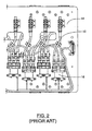
- FIG. 2 illustrates a spacecraft panel comprising of circulators 14 and switches 16 using RF cables 10 to interconnect flight components that could otherwise be bolted together. As shown, the width of a cable-connected panel layout is 16 inches (40.7 cm).
- the RF cables 10 that are used to attach circulators 14 to switches 16 are 5 inches (12.7cm) long, and accordingly are a critical limiting factor for the overall panel width. Without the interconnecting cables, the width of this panel can be reduced by approximately 4 inches (10.2 cm).
- RF components when RF components are directly connected through connectors without the need for cables, the power-handling capability of the components is substantially reduced.
- RF cables provide radial heat transfer from the center conductor to the outer sheath, and when this radial thermal heat path is absent, the center conductors of the individual components become hotter than they would otherwise be, thus further limiting the power-handling capability of multiple power component assemblies.
- conventional RF cable connectors are not designed to provide heat sinking functionality between RF components. Rather, RF cable connectors typically use a Teflon-based insulation layer between the center and outer conductors, which does not promote conduction of heat from the center conductor to the outer conductor due to its poor thermal conductivity.
- the invention provides in one aspect, a heat sink connector for providing a heat transfer path from the conductors of a first coaxial cable connector to a heat sink, said heat sink connector comprising:
- FIGS. 3 and 4 illustrate a heat sink connector 20 built in accordance with the present invention.
- heat sink connector 20 includes a center conductor 22, an outer conductor 24, an insulation layer 26, a thermal element 28, a male TNC connector 30 and a female TNC connector 32.
- heat sink connector 20 provides an efficient method of sinking heat from the center and outer conductors of attached RF power components or RF cables to a spacecraft environment.
- Heat sink connector 20 increases the power handing ability of the overall component assembly and isolates RF power components from the heat loads associated with connecting cables preventing associated detrimental effects.
- Heat sink connector 20 also allows for effective thermal isolation of bolted together RF components.
- Center conductor 22 is a conventional TNC center conductor and is made of an electrically conductive material (i.e. a solid metal wire). Center conductor 22 is covered by insulation layer 26 (FIG. 4). The thickness and other physical dimensions of center conductor 22 is related to the desired impedance of heat sink connector 20 (which also depends on the dielectric constant of insulation layer 26).
- Outer conductor 24 surrounds insulation layer 26 and has the thickness and other physical dimensions of a conventional TNC outer conductor.
- Outer conductor 24 may be a braid, a foil or a solid metal.
- Insulation layer 26 is formed out of an insulator, and is preferably a dielectric material with high thermal conductivity.
- insulation layer 26 can be comprised of FluoroloyTM dielectric material (manufactured by Furon Saint-Gobain, France) that has high thermal conductivity, provides a high degree of heat transfer, and minimizes material creep deformation.
- Thermal conductivity is a property of materials that expresses the heat flux f (W/m 2 ) that will flow through the material if a certain temperature gradient ⁇ T (K/m) exists over the material.
- Fluoroloy dielectric material is five times more thermally conductive than the TeflonTM (manufactured by Dupont of Delaware) dielectric material conventionally used in TNC connectors.
- insulation layer 26 is designed to provide a high degree of heat transfer from center conductor 22 to outer conductor 24.
- insulation layer 26 While it is preferred for insulation layer 26 to have a high thermal conductivity, any material having a thermal conductivity higher than that of Teflon (i.e. greater than 0.24 W/m C) would be suitable for application within heat sink connector 20. At the same time, it is important to ensure that the relative coefficients of thermal expansion (CTE) of insulation layer 26, center conductor 22, outer conductor 24, male and female TNC connectors 30 and 32 are such that when heated, insulation layer 26 and the other components sufficiently expand to maintain good material contact at the inner and outer interfaces of male and female TNC connectors 30 and 32.
- CTE coefficients of thermal expansion
- Male TNC connector 30 is provided on one end of heat sink connector 20 and a female TNC connector 32 is provided on the other end.
- Connectors 30 and 32 are conventional TNC connectors adapted to receive the female and male TNC connectors and fastening elements, respectively of a conventional cable connector assembly.
- Male TNC connector 30 includes a conventional adaptor nut 31 having internal threads (not shown) for conventional coupling to a female TNC cable connector which is typically provided on the signal inputs and outputs of an RF power component.
- Female TNC connector 32 has external threads 33 for conventional coupling to male TNC connectors on RF cables.
- the configuration of male and female TNC connectors 30 and 32 discussed above can be used to couple heat sink connector 20 between a RF component (i.e. typically having a female connector) and a RF cable connector (i.e. typically having a male connector).
- RF components typically feature female connectors at their signal inputs and outputs in order to minimize breakage of the center conductor prong.
- heat sink connector 20 has been shown in association with a male/female connector pair, it could be just as easily be constructed using any configuration of TNC connectors (e.g. as an adaptor with male/male or female/female) as appropriate for a particular application (i.e. depending on the TNC cable connection requirements between electrical components at issue).
- TNC connectors e.g. as an adaptor with male/male or female/female
- heat sink connector 20 be used to "bolt" together RF components, each of which would have female TNC connectors.
- heat sink connector 20 could just as easily be provided with two male TNC connectors 30, one at each end.
- heat sink connector 20 be constructed having only one male or female TNC connector as required for a particular heat sink application.
- heat sink connector 20 constructed with only one male or female TNC connector would provide heat sink capability to a single TNC cable or an individual piece of equipment having a complementary TNC cable connector.
- Thermal element 28 is configured as a tab and is used to provide a heat-sinking path from outer conductor 24 to an external heat sink bracket (not shown).
- thermal element 28 is a substantially rectangular planar segment that is coupled to outer conductor 24 through a section of the outer shell 27.
- Thermal element 28 is designed to protrude from the outer shell 27 with sufficient clearance and surface area to form thermal contact with an external heat sinking bracket which in turn absorbs the heat from thermal element 28 and dissipates this heat from heat sink connector 20 to a heat sink.
- Thermal element 28 contains holes 29 through which fasteners (not shown) can be used to bolt thermal element 28 to the external heat sinking bracket.
- thermal element 28 could be any other shape which has a surface adapted to be coupled to the outer conductor and to a heat sink.
- heat sink connector 20 when heat sink connector 20 is connected to a TNC male cable connector 39, heat sink connector 20 provides the conductors of the TNC male cable connector 39 with two critical heat paths. Specifically, the external threads 33 of female TNC connector 32 are engaged by the threads of the male TNC adaptor nut 44 of TNC male cable connector 39, such that the center conductor prong 43 is electrically coupled to center conductor 22 of heat sink connector 20.
- TNC male cable connector 39 electrically couples center cable conductor 38 and outer cable conductor 41 to the center conductor 22 and outer conductor 24, respectively as shown.
- the first heat path provided by heat sink connector 20 is the radial heat path (see arrow A in FIG. 5) from center conductor 22 (which receives heat from center conductor prong 43) to outer conductor 24.
- the second path is from outer conductor 24 to the thermal element 28.
- the length of heat sink connector 20 is dictated by the longitudinal dimension of male TNC connector 30, female TNC connector 32 and the necessary clearance required by thermal element 28. Given the conventional dimensions of the TNC male and female connectors and the relatively minimal clearance required for access to thermal element 28, the overall lengthwise dimension of heat sink conductor 20 can be comparable to that of a conventional TNC cable connector, and as little as 1 inch (2.54 cm).
- Heat sink connector 20 can be bolted between a RF power component and RF cables to prevent heat loads from connecting RF cables from causing detrimental effects on the RF component. Alternatively, heat sink connector 20 can be coupled between two critical RF power components. Because heat sink connector 20 is relatively short and of low mass, it does not have a significant impact on component assembly footprint or overall component assembly mass.
- Heat sink connector 20 provides heat paths to dissipate heat within coaxial cable equipment that conventionally limits the power handling capability of a RF power component. Based on a thermal analysis, the inventors contemplate that heat sink connector 20 can reduce the temperature of the center conductors of high RF power components by 10 degrees Celsius. This decrease corresponds to a 20% increase in power handling capability of RF components which are bolted together, given the current power-handling limit.. Further, by using heat sink connector 20 instead of RF cables for heat isolation of RF components, a significant reduction in size, weight and cost for high power RF component assemblies can be achieved as discussed above.
- heat sink connector 20 provides an efficient mechanism for transferring heat from the center conductor of RF cables and RF power components to a heat sink bracket.
- Heat sink connector 20 allows for effective thermal isolation of bolted together RF components by providing a heat transfer path for RF connections. Heat sink connector 20 can also be bolted between a RF power component and a RF cable to prevent heat loads from the RF cable from causing detrimental effects on the RF component.
- heat sink connector 20 having only one male or female TNC connector can provide heat sink capability to a single TNC cable or an individual piece of equipment having a complementary TNC cable connector. Heat sink connector 20 provides an especially critical benefit where power handling within a RF component assembly is a critical design requirement. Also, since the male and female TNC connectors 30 and 32 can be easily attached and detached from other connectors on RF power equipment or TNC cables, heat sink connector 20 can be conveniently utilized within conventional RF power component assemblies.
- heat sink connector 20 can be used in a wide variety of applications including flight multiplexer assembly hardware and high power test setups.
- a multiplexer MUX
- MUX multiplexer
- Multiplexers can be designed and manufactured as individual multiplexers or as combined assemblies of multiplexers with complex input circuits.
- the input circuits consist waveguides or RF cables which route signals through switches to provide a redundancy network in which RF signals can be transferred from various amplifiers to specific channel filters.
- Heat sink 20 allows for the isolation of RF components such a filter or switch from RF cable losses. Heat sink 20 can also provide similar functionality for high power RF test applications which are typically carried out in a thermal vacuum environment. Test RF cables also dissipate heat that can be detrimental to RF components. Heat sink connector 20 can isolate the RF component from the RF cable losses, and accordingly prevent unwarranted component testing failures.
- heat sink connector 20 could also be implemented for other types pf radio frequency connectors such as PTNC and SMA connectors.
Landscapes
- Connector Housings Or Holding Contact Members (AREA)
Abstract
Description
- This invention relates to coaxial cable equipment and more particularly to a coaxial heat sink connector.
- The power handling capability of radio frequency (RF) components is significantly affected by the design of interconnecting coaxial RF cables ("coax"), which are widely used to connect RF components due to their large bandwidth capabilities. Heat dissipated in RF cables is generally transferred to the environment through radiation from the RF cable, and through conduction from the ends of the RF cable to the cable-connected RF components. In ground applications, convection helps reduce cable temperatures and accordingly, center conductor temperatures. In the case of electronic components for use in space applications, since there is no mechanism for convective heat transfer from the outer cable surfaces, other means of providing heat dissipation must be considered.
- Generally, the length, design, and power level of the RF cables have a significant impact on the power-handling capability of RF components. This is especially the case in the thermal design of RF components for space applications, as the worst-case temperatures, de-rated power levels and worst-case dissipation specifications combine to ensure that temperature predictions bound any kind of flight applications. Fault conditions become especially difficult to design for, as typical fault scenarios result in full reflection of RF power through the RF cables, the RF cable connectors and the RF components. This full reflection can result in almost twice the rated power passing through an RF cable.
- As shown in FIG. 1,
RF cables 10 which are used in space applications are conventionally clamped to a heat sink (not shown) using acable clamp 12. A heat sink is a device that is attached to heat generating equipment to prevent overheating by absorbing heat from the equipment and dissipating it into the immediate environment. This kind of assembly as shown in FIG. 1 provides a conduction point (i.e. at the cable clamp 12) for heat transfer fromRF cable 10 and also ensures thatRF cable 10 structurally adheres to a support structure. However, since the ends ofRF cable 10 are too rigid to make suitable physical contact withcable clamp 12,cable clamp 12 must be positioned near the center ofRF cable 10. Accordingly, this arrangement does not consistently sink heat from the center conductor ofRF cable 10 and RF components. - In space applications, it is desirable to reduce the mass and equipment footprint of RF component assemblies and to reduce RF losses generally. By what is conventionally known as "bolting" together high power components using connectors instead of intermediate RF cables, several improvements can be realized. First, there is a substantial reduction of mass when components are bolted together as compared to when they are RF cabled together. As shown in FIG. 2, RF power components (
e.g. circulators 14 and switches 16) are typically connected by long sections ofRF cable 10 as long sections are required to minimize the thermal stress onRF cable 10 for durability and long life. Typically, eachRF cable 10 is at least 6 inches (15.3 cm) long with each pair of cables having a typical mass of 45 grams. Moreover, when several pairs of these cables are used the cumulative mass can be appreciable. Also, there is an improvement in RF performance due to the absence of RF losses associated with an intermediate cable. - Further, when RF components are bolted together, the equipment footprint of the complete assembly is slightly larger than the cumulative footprint of the individual components (due to the short length of TNC connectors). In contrast, when RF cables are used between components a suitable spacing is required to house the lengthy RF cables, and as a result the assembly has a larger overall footprint. Accordingly, the RF-cabled assembly takes up more room on a spacecraft, has a higher overall mass, and has a higher overall cost. FIG. 2 illustrates a spacecraft panel comprising of
circulators 14 andswitches 16 usingRF cables 10 to interconnect flight components that could otherwise be bolted together. As shown, the width of a cable-connected panel layout is 16 inches (40.7 cm). In this case, theRF cables 10 that are used to attachcirculators 14 to switches 16 are 5 inches (12.7cm) long, and accordingly are a critical limiting factor for the overall panel width. Without the interconnecting cables, the width of this panel can be reduced by approximately 4 inches (10.2 cm). - However, when RF components are directly connected through connectors without the need for cables, the power-handling capability of the components is substantially reduced. First, when two high power components are bolted to each other, they interact with each other thermally (i.e. one component heats up the other). Also, RF cables provide radial heat transfer from the center conductor to the outer sheath, and when this radial thermal heat path is absent, the center conductors of the individual components become hotter than they would otherwise be, thus further limiting the power-handling capability of multiple power component assemblies. Also, conventional RF cable connectors are not designed to provide heat sinking functionality between RF components. Rather, RF cable connectors typically use a Teflon-based insulation layer between the center and outer conductors, which does not promote conduction of heat from the center conductor to the outer conductor due to its poor thermal conductivity.
- The invention provides in one aspect, a heat sink connector for providing a heat transfer path from the conductors of a first coaxial cable connector to a heat sink, said heat sink connector comprising:
- (a) a body comprising:
- (i) a center conductor:
- (ii) an outer conductor disposed around said center conductor;
- (iii) an insulation layer positioned between said center conductor and said outer conductor, said insulative layer being selected to have a substantially high degree of thermal conductivity such that a substantial amount of heat is conducted from the center conductor to the outer conductor;
- (b) a first connector positioned at one end of said body, said first connector being electrically coupled to said center conductor and said outer conductor, said first connector being adapted to electrically couple said center and outer conductors to the conductors of the first coaxial cable connector; and
- (c) a thermal element coupled to the outer conductor, said thermal element having a surface adapted to be coupled to a heat sink such that said heat sink connector provides a heat transfer path from the conductors of the first coaxial cable connector to the heat sink through said center and outer conductors.
-
- Further aspects and advantages of the invention will appear from the following description taken together with the accompanying drawings.
- In the accompanying drawings:
- FIG. 1 is a top view of a prior art RF cable assembly showing how a cable clamp can be used to couple a RF cable to a heat sink;
- FIG. 2 is a top view of a prior art RF cable-connected power component spacecraft panel layout showing how RF cables are used to interconnect RF power components;
- FIG. 3 is a side perspective view of the co-axial heat sink connector of the present invention;
- FIG. 4 is a longitudinal partial cut-away view of the co-axial heat sink connector of FIG. 3 taken along the line A-A'; and
- FIG. 5 is a cross-sectional view of the co-axial heat sink connector of FIG. 3 engaged with a male TNC cable connector taken along the line A-A'.
-
- FIGS. 3 and 4 illustrate a
heat sink connector 20 built in accordance with the present invention. Specifically,heat sink connector 20 includes acenter conductor 22, anouter conductor 24, aninsulation layer 26, athermal element 28, amale TNC connector 30 and afemale TNC connector 32. As will be described,heat sink connector 20 provides an efficient method of sinking heat from the center and outer conductors of attached RF power components or RF cables to a spacecraft environment.Heat sink connector 20 increases the power handing ability of the overall component assembly and isolates RF power components from the heat loads associated with connecting cables preventing associated detrimental effects.Heat sink connector 20 also allows for effective thermal isolation of bolted together RF components. -
Center conductor 22 is a conventional TNC center conductor and is made of an electrically conductive material (i.e. a solid metal wire).Center conductor 22 is covered by insulation layer 26 (FIG. 4). The thickness and other physical dimensions ofcenter conductor 22 is related to the desired impedance of heat sink connector 20 (which also depends on the dielectric constant of insulation layer 26). -
Outer conductor 24 surroundsinsulation layer 26 and has the thickness and other physical dimensions of a conventional TNC outer conductor.Outer conductor 24 may be a braid, a foil or a solid metal. -
Insulation layer 26 is formed out of an insulator, and is preferably a dielectric material with high thermal conductivity. For example,insulation layer 26 can be comprised of Fluoroloy™ dielectric material (manufactured by Furon Saint-Gobain, France) that has high thermal conductivity, provides a high degree of heat transfer, and minimizes material creep deformation. Thermal conductivity is a property of materials that expresses the heat flux f (W/m2) that will flow through the material if a certain temperature gradient ΔT (K/m) exists over the material. Fluoroloy dielectric material is five times more thermally conductive than the Teflon™ (manufactured by Dupont of Delaware) dielectric material conventionally used in TNC connectors. Specifically, the thermal conductivity of Fluoroloy H is 1.21 W/m C, while that of Teflon PTFE is 0.24 W/m C. Accordingly,insulation layer 26 is designed to provide a high degree of heat transfer fromcenter conductor 22 toouter conductor 24. - While it is preferred for
insulation layer 26 to have a high thermal conductivity, any material having a thermal conductivity higher than that of Teflon (i.e. greater than 0.24 W/m C) would be suitable for application withinheat sink connector 20. At the same time, it is important to ensure that the relative coefficients of thermal expansion (CTE) ofinsulation layer 26,center conductor 22,outer conductor 24, male andfemale TNC connectors insulation layer 26 and the other components sufficiently expand to maintain good material contact at the inner and outer interfaces of male andfemale TNC connectors -
Male TNC connector 30 is provided on one end ofheat sink connector 20 and afemale TNC connector 32 is provided on the other end.Connectors Male TNC connector 30 includes aconventional adaptor nut 31 having internal threads (not shown) for conventional coupling to a female TNC cable connector which is typically provided on the signal inputs and outputs of an RF power component.Female TNC connector 32 hasexternal threads 33 for conventional coupling to male TNC connectors on RF cables. The configuration of male andfemale TNC connectors heat sink connector 20 between a RF component (i.e. typically having a female connector) and a RF cable connector (i.e. typically having a male connector). RF components typically feature female connectors at their signal inputs and outputs in order to minimize breakage of the center conductor prong. - Generally, it should be understood that while
heat sink connector 20 has been shown in association with a male/female connector pair, it could be just as easily be constructed using any configuration of TNC connectors (e.g. as an adaptor with male/male or female/female) as appropriate for a particular application (i.e. depending on the TNC cable connection requirements between electrical components at issue). For example, it is also contemplated thatheat sink connector 20 be used to "bolt" together RF components, each of which would have female TNC connectors. Accordingly,heat sink connector 20 could just as easily be provided with twomale TNC connectors 30, one at each end. It is also contemplated thatheat sink connector 20 be constructed having only one male or female TNC connector as required for a particular heat sink application. Specifically,heat sink connector 20 constructed with only one male or female TNC connector would provide heat sink capability to a single TNC cable or an individual piece of equipment having a complementary TNC cable connector. -
Thermal element 28 is configured as a tab and is used to provide a heat-sinking path fromouter conductor 24 to an external heat sink bracket (not shown).thermal element 28 is a substantially rectangular planar segment that is coupled toouter conductor 24 through a section of theouter shell 27.Thermal element 28 is designed to protrude from theouter shell 27 with sufficient clearance and surface area to form thermal contact with an external heat sinking bracket which in turn absorbs the heat fromthermal element 28 and dissipates this heat fromheat sink connector 20 to a heat sink.Thermal element 28 containsholes 29 through which fasteners (not shown) can be used to boltthermal element 28 to the external heat sinking bracket. It should be understood that any kind of conventional coupling mechanism can be used withinthermal element 28 to allow for thermal contact with an external heat sinking bracket (e.g. a slotted arrangement). It should be understoodthermal element 28 could be any other shape which has a surface adapted to be coupled to the outer conductor and to a heat sink. - As shown in FIG. 5, when
heat sink connector 20 is connected to a TNCmale cable connector 39,heat sink connector 20 provides the conductors of the TNCmale cable connector 39 with two critical heat paths. Specifically, theexternal threads 33 offemale TNC connector 32 are engaged by the threads of the maleTNC adaptor nut 44 of TNCmale cable connector 39, such that thecenter conductor prong 43 is electrically coupled tocenter conductor 22 ofheat sink connector 20. In a conventional manner, TNCmale cable connector 39 electrically couplescenter cable conductor 38 andouter cable conductor 41 to thecenter conductor 22 andouter conductor 24, respectively as shown. Similarly, a TNC female cable connector (not shown) would normally be engaged byinternal threads 37 ofmale TNC connector 31 such thatcenter conductor prong 49 would be electrically coupled to the center conductor of TNC female cable connector. The first heat path provided byheat sink connector 20 is the radial heat path (see arrow A in FIG. 5) from center conductor 22 (which receives heat from center conductor prong 43) toouter conductor 24. The second path (see arrow B in FIG. 5) is fromouter conductor 24 to thethermal element 28. - The length of
heat sink connector 20 is dictated by the longitudinal dimension ofmale TNC connector 30,female TNC connector 32 and the necessary clearance required bythermal element 28. Given the conventional dimensions of the TNC male and female connectors and the relatively minimal clearance required for access tothermal element 28, the overall lengthwise dimension ofheat sink conductor 20 can be comparable to that of a conventional TNC cable connector, and as little as 1 inch (2.54 cm).Heat sink connector 20 can be bolted between a RF power component and RF cables to prevent heat loads from connecting RF cables from causing detrimental effects on the RF component. Alternatively,heat sink connector 20 can be coupled between two critical RF power components. Becauseheat sink connector 20 is relatively short and of low mass, it does not have a significant impact on component assembly footprint or overall component assembly mass. -
Heat sink connector 20 provides heat paths to dissipate heat within coaxial cable equipment that conventionally limits the power handling capability of a RF power component. Based on a thermal analysis, the inventors contemplate thatheat sink connector 20 can reduce the temperature of the center conductors of high RF power components by 10 degrees Celsius. This decrease corresponds to a 20% increase in power handling capability of RF components which are bolted together, given the current power-handling limit.. Further, by usingheat sink connector 20 instead of RF cables for heat isolation of RF components, a significant reduction in size, weight and cost for high power RF component assemblies can be achieved as discussed above. - Accordingly,
heat sink connector 20 provides an efficient mechanism for transferring heat from the center conductor of RF cables and RF power components to a heat sink bracket.Heat sink connector 20 allows for effective thermal isolation of bolted together RF components by providing a heat transfer path for RF connections.Heat sink connector 20 can also be bolted between a RF power component and a RF cable to prevent heat loads from the RF cable from causing detrimental effects on the RF component. Finally,heat sink connector 20 having only one male or female TNC connector can provide heat sink capability to a single TNC cable or an individual piece of equipment having a complementary TNC cable connector.Heat sink connector 20 provides an especially critical benefit where power handling within a RF component assembly is a critical design requirement. Also, since the male andfemale TNC connectors heat sink connector 20 can be conveniently utilized within conventional RF power component assemblies. - It is contemplated that
heat sink connector 20 can be used in a wide variety of applications including flight multiplexer assembly hardware and high power test setups. As is conventionally known, a multiplexer (MUX) is a component consisting of bandpass filters multiplexed on a common manifold. Its purpose is to combine individual channels of RF signals into a single unit, which are subsequently beamed back to earth from an orbiting satellite. Multiplexers can be designed and manufactured as individual multiplexers or as combined assemblies of multiplexers with complex input circuits. The input circuits consist waveguides or RF cables which route signals through switches to provide a redundancy network in which RF signals can be transferred from various amplifiers to specific channel filters. - Proper thermal design of this redundancy network is critical since fault scenarios contemplate a doubling of input RF power back through RF cables resulting in a significant heating effect on the center conductors of these RF cables. Consequently, the center conductors transfer heat to the components which these cables link together.
Heat sink 20 allows for the isolation of RF components such a filter or switch from RF cable losses.Heat sink 20 can also provide similar functionality for high power RF test applications which are typically carried out in a thermal vacuum environment. Test RF cables also dissipate heat that can be detrimental to RF components.Heat sink connector 20 can isolate the RF component from the RF cable losses, and accordingly prevent unwarranted component testing failures. - It should be understood that the configuration of
heat sink connector 20 could also be implemented for other types pf radio frequency connectors such as PTNC and SMA connectors. As will be apparent to those skilled in the art, various modifications and adaptations of the structure described above are possible without departing from the present invention, the scope of which is defined in the appended claims.
Claims (9)
Applications Claiming Priority (4)
| Application Number | Priority Date | Filing Date | Title |
|---|---|---|---|
| US43123702P | 2002-12-06 | 2002-12-06 | |
| US431237P | 2002-12-06 | ||
| US407242 | 2003-04-07 | ||
| US10/407,242 US6733324B1 (en) | 2002-12-06 | 2003-04-07 | Coaxial heat sink connector |
Publications (1)
| Publication Number | Publication Date |
|---|---|
| EP1427069A1 true EP1427069A1 (en) | 2004-06-09 |
Family
ID=32233364
Family Applications (1)
| Application Number | Title | Priority Date | Filing Date |
|---|---|---|---|
| EP03257659A Withdrawn EP1427069A1 (en) | 2002-12-06 | 2003-12-05 | Coaxial heat sink connector |
Country Status (3)
| Country | Link |
|---|---|
| US (1) | US6733324B1 (en) |
| EP (1) | EP1427069A1 (en) |
| CA (1) | CA2448950A1 (en) |
Cited By (2)
| Publication number | Priority date | Publication date | Assignee | Title |
|---|---|---|---|---|
| DE102008022100A1 (en) * | 2008-04-15 | 2009-10-22 | Rohde & Schwarz Gmbh & Co. Kg | Coaxial connector with thermal decoupling |
| EP2256876A1 (en) | 2009-05-29 | 2010-12-01 | Radiall | Very-high-power connector |
Families Citing this family (13)
| Publication number | Priority date | Publication date | Assignee | Title |
|---|---|---|---|---|
| US7080989B2 (en) * | 2004-06-10 | 2006-07-25 | Sun Microsystems, Inc. | Memory metal springs for heatsink attachments |
| US7128604B2 (en) * | 2004-06-14 | 2006-10-31 | Corning Gilbert Inc. | High power coaxial interconnect |
| US6976884B1 (en) * | 2005-03-23 | 2005-12-20 | Chun Te Lee | Securing device for the adapter of a cable intermediate connector |
| US7705238B2 (en) | 2006-05-22 | 2010-04-27 | Andrew Llc | Coaxial RF device thermally conductive polymer insulator and method of manufacture |
| US7494374B2 (en) * | 2007-02-01 | 2009-02-24 | Tyco Electronics Corporation | Panel mount electrical connector |
| US8322977B2 (en) * | 2009-07-22 | 2012-12-04 | Siemens Energy, Inc. | Seal structure for preventing leakage of gases across a gap between two components in a turbine engine |
| KR101917052B1 (en) * | 2010-01-22 | 2019-01-30 | 누보트로닉스, 인크. | Thermal management |
| US8814601B1 (en) | 2011-06-06 | 2014-08-26 | Nuvotronics, Llc | Batch fabricated microconnectors |
| US9443683B2 (en) | 2012-04-24 | 2016-09-13 | Commscope Technologies Llc | RF thermal fuse |
| US8926360B2 (en) * | 2013-01-17 | 2015-01-06 | Cooper Technologies Company | Active cooling of electrical connectors |
| US9252512B2 (en) | 2013-08-14 | 2016-02-02 | Hamilton Sundstrand Corporation | Power connector having enhanced thermal conduction characteristics |
| CN108063338A (en) * | 2018-01-19 | 2018-05-22 | 无锡百祺电子科技有限公司 | A kind of solar energy connector with route protection |
| CN111740270B (en) * | 2020-07-30 | 2024-05-07 | 中国工程物理研究院总体工程研究所 | Connector adapter of high-temperature irradiation-resistant waterproof TNC (TNC) adapter M5 socket |
Citations (3)
| Publication number | Priority date | Publication date | Assignee | Title |
|---|---|---|---|---|
| US4687279A (en) * | 1985-12-20 | 1987-08-18 | Storm Products Co. | High frequency coaxial connector adaptor |
| JPH0817522A (en) * | 1994-06-28 | 1996-01-19 | Nec Eng Ltd | Coaxial connector and its assembly |
| JP2000349501A (en) * | 1999-06-01 | 2000-12-15 | Fujitsu Ltd | Connection structure of high power high frequency transmission line |
Family Cites Families (7)
| Publication number | Priority date | Publication date | Assignee | Title |
|---|---|---|---|---|
| US4189683A (en) * | 1978-10-25 | 1980-02-19 | Raytheon Company | Solid state diode amplifier |
| US4506939A (en) * | 1983-01-31 | 1985-03-26 | General Electric Company | Arrangement for connecting printed circuit boards |
| US4588963A (en) * | 1983-12-20 | 1986-05-13 | Hughes Aircraft Company | Microwave power combiner with alternating diode modules |
| US5030961A (en) * | 1990-04-10 | 1991-07-09 | Ford Aerospace Corporation | Microstrip antenna with bent feed board |
| US5124883A (en) * | 1990-10-31 | 1992-06-23 | Elcon Products International Company | Printed circuit board power plug contact |
| US6146208A (en) | 1997-06-17 | 2000-11-14 | Commscope | Field connector adaptor |
| US6623279B2 (en) * | 1999-07-15 | 2003-09-23 | Incep Technologies, Inc. | Separable power delivery connector |
-
2003
- 2003-04-07 US US10/407,242 patent/US6733324B1/en not_active Expired - Lifetime
- 2003-11-12 CA CA002448950A patent/CA2448950A1/en not_active Abandoned
- 2003-12-05 EP EP03257659A patent/EP1427069A1/en not_active Withdrawn
Patent Citations (3)
| Publication number | Priority date | Publication date | Assignee | Title |
|---|---|---|---|---|
| US4687279A (en) * | 1985-12-20 | 1987-08-18 | Storm Products Co. | High frequency coaxial connector adaptor |
| JPH0817522A (en) * | 1994-06-28 | 1996-01-19 | Nec Eng Ltd | Coaxial connector and its assembly |
| JP2000349501A (en) * | 1999-06-01 | 2000-12-15 | Fujitsu Ltd | Connection structure of high power high frequency transmission line |
Non-Patent Citations (2)
| Title |
|---|
| PATENT ABSTRACTS OF JAPAN vol. 1996, no. 05 31 May 1996 (1996-05-31) * |
| PATENT ABSTRACTS OF JAPAN vol. 2000, no. 15 6 April 2001 (2001-04-06) * |
Cited By (4)
| Publication number | Priority date | Publication date | Assignee | Title |
|---|---|---|---|---|
| DE102008022100A1 (en) * | 2008-04-15 | 2009-10-22 | Rohde & Schwarz Gmbh & Co. Kg | Coaxial connector with thermal decoupling |
| US8333611B2 (en) | 2008-04-15 | 2012-12-18 | Rohde & Schwarz Gmbh & Co. Kg | Coaxial plug-connector part with thermal decoupling |
| EP2256876A1 (en) | 2009-05-29 | 2010-12-01 | Radiall | Very-high-power connector |
| US8414327B2 (en) | 2009-05-29 | 2013-04-09 | Radiall | Very high power connector |
Also Published As
| Publication number | Publication date |
|---|---|
| US6733324B1 (en) | 2004-05-11 |
| CA2448950A1 (en) | 2004-06-06 |
Similar Documents
| Publication | Publication Date | Title |
|---|---|---|
| US6733324B1 (en) | Coaxial heat sink connector | |
| US12308505B2 (en) | Connecting electrical circuitry in a quantum computing system | |
| US9088094B2 (en) | Electrical connector having a plug and a socket with electrical connection being made while submerged in an inert fluid | |
| US5488380A (en) | Packaging architecture for phased arrays | |
| EP1097488B1 (en) | Rf connector | |
| EP1489692B1 (en) | Termination structure of cryogenic cable | |
| US5950444A (en) | Electronic apparatus | |
| US10998605B2 (en) | Connecting unit for connecting to first and second interfaces, where the connecting unit comprises an internal conductor disposed within a housing formed by half-shell construction | |
| WO2001057886A1 (en) | Heat-insulated signal transmission unit and superconducting signal transmission device | |
| JP2000500919A (en) | Compressible coaxial interconnect with integrated environmental seal | |
| US9559552B2 (en) | Coaxial cable and connector with capacitive coupling | |
| CN102548209A (en) | Flexible circuit assemblies with stacked flex interconnects and connector assemblies having the same | |
| US10312565B1 (en) | Microwave power divider/combiner devices, microwave power divider/combiner bandpass filters, and methods of thermally cooling a cable run | |
| CN120978429B (en) | Electrical connectors, signal transmission devices, and dilution refrigeration units | |
| JP3631432B2 (en) | Low PIM coaxial diplexer interface | |
| US10992272B2 (en) | High-frequency module with connection interface | |
| JPH09512130A (en) | Cryogenic cable | |
| KR100627511B1 (en) | Superconducting power cable connection system and conductor sleeves used in it | |
| US20240136748A1 (en) | Contact assembly for an electrical plug-in connector having a heat capacity element arranged on a contact element | |
| US20230170641A1 (en) | Cryogenic chamber connector | |
| US5247267A (en) | Utilizing thermal conductors to increase operating power of coaxial microwave devices | |
| US20240412896A1 (en) | Co-axial interconnect for low temperature applications | |
| CN117730457A (en) | Transmission line | |
| WO2004066488A2 (en) | High power switchable power combiner | |
| JPH08195510A (en) | Thermoelectric module |
Legal Events
| Date | Code | Title | Description |
|---|---|---|---|
| PUAI | Public reference made under article 153(3) epc to a published international application that has entered the european phase |
Free format text: ORIGINAL CODE: 0009012 |
|
| AK | Designated contracting states |
Kind code of ref document: A1 Designated state(s): AT BE BG CH CY CZ DE DK EE ES FI FR GB GR HU IE IT LI LU MC NL PT RO SE SI SK TR |
|
| AX | Request for extension of the european patent |
Extension state: AL LT LV MK |
|
| 17P | Request for examination filed |
Effective date: 20041004 |
|
| AKX | Designation fees paid |
Designated state(s): DE FR GB |
|
| RBV | Designated contracting states (corrected) |
Designated state(s): DE FR GB |
|
| STAA | Information on the status of an ep patent application or granted ep patent |
Free format text: STATUS: THE APPLICATION IS DEEMED TO BE WITHDRAWN |
|
| 18D | Application deemed to be withdrawn |
Effective date: 20070703 |