BACKGROUND OF THE INVENTION
Field of the Invention
The present invention relates to an apparatus and method for detecting
very small distances, and more particularly to proximity sensing with gas
flow.
Related Art
Many automated manufacturing processes require the sensing of the
distance between a manufacturing tool and the product or material surface
being worked. In some situations, such as semiconductor lithography, the
distance must be measured with accuracy approaching a nanometer.
The challenges associated with creating a proximity sensor of such
accuracy are significant, particularly in the context of photolithography
systems. In the photolithography context, in addition to being non-intrusive
and having the ability to precisely detect very small distances, the proximity
sensor can not introduce contaminants or come in contact with the work
surface, typically a semiconductor wafer. Occurrence of either situation may
significantly degrade or ruin the semiconductor quality.
Different types of proximity sensors are available to measure very
small distances. Examples of proximity sensors include capacitance and
optical gauges. These proximity sensors have serious shortcomings when
used in photolithography systems because physical properties of materials
deposited on wafers may impact the precision of these devices. For example,
capacitance gauges, being dependent on the concentration of electric charges,
can yield spurious proximity readings in locations where one type of material
(e.g., metal) is concentrated. Another class of problems occurs when exotic
wafers made of non-conductive and/or photosensitive materials, such as
Gallium Arsenide (GaAs) and Indium Phosphide (InP), are used. In these
cases, capacitance and optical gauges may provide spurious results.
U.S. Patents 4,953,388 and 4,550,592 disclose an alternative approach
to proximity sensing that uses an air gauge sensor. An air gauge sensor is not
vulnerable to concentrations of electric charges or electrical, optical and other
physical properties of a wafer surface. Current semiconductor manufacturing,
however, requires that proximity is gauged with high precision on the order of
nanometers. What is needed is a more precise gas gauge proximity sensor
than those described in the above U.S. patents.
SUMMARY OF THE INVENTION
The present invention provides a high-resolution gas gauge proximity
sensor and method that significantly improves on the precision of previous
types of proximity sensors. The gas gauge proximity sensor determines
proximity by detecting a difference in measurement and reference standoffs.
A standoff is the distance or gap between a nozzle of the proximity sensor and
the surface beneath the nozzle.
To determine the standoff difference, a flow of gas with a constant
mass flow rate is metered with a mass flow controller and is forced through
two channels - a measurement channel and a reference channel. According to
the present invention, porous restrictors are used in the reference channel and
measurement channel. The porous restrictors introduce no turbulence and
reduce pneumatic noise, while performing a resistive function required for
proper operation of the sensor. In alternate embodiments of the present
invention, a porous snubber is placed within the proximity sensor following
the mass flow controller and before the proximity sensor bifurcates into the
reference and measurement channel. The porous snubber quiets gas
turbulence and reduces possible acoustic noise propagated through the
channels, and enhances the proximity sensor's precision.
Each channel has a probe on the distal end that is positioned above a
surface. A gas is forced through the channels and emitted through nozzles
against respective measurement and reference surfaces. A bridge channel
between the reference and measurement channels senses mass flow between
the two channels that is induced by differences in the gas pressure in the
reference and measurement channel. The sensed mass flow rate is
representative of the difference in reference and measurement standoffs. In
other words, the sensed mass flow across the bridge is representative of any
difference between a reference standoff of a reference probe and reference
surface in the reference channel and a measurement standoff of a measurement
probe and a measurement surface in the measurement channel. The gas gauge
proximity sensor can provide an indication and invoke a control action based
on the sensed mass flow rate.
According to a further aspect of the present invention, different nozzle
types can be used as measurement and reference probes. These nozzles enable
the sensor to be readily adapted for different types of work surfaces.
According to a further aspect of the present invention, a gas gauge
proximity sensor can contain a measurement channel connected to a switching
device that connects to multiple measurement branches. Each of the
measurement branches has characteristics that are the same as those of a
measurement channel in a device that does not contain measurement branches.
Multiple measurement branches enhance the ability of a proximity sensor to
measure standoffs over a larger region of a measurement surface.
According to a further embodiment of the present invention, a method
is provided for a gas gauge proximity sensor with a single measurement
channel. The method includes steps of distributing gas flow into measurement
and reference channels, and restricting gas flow evenly across cross-sectional
areas of each channel.
According to a further embodiment of the present invention, a method
is provided for a gas gauge proximity sensor with multiple measurement
branches. The method includes steps of distributing gas flow into a
measurement branch and a reference channel, restricting gas flow evenly
across cross-sectional areas of the reference channel or a measurement branch,
and switching between measurement branches. An additional method
describes the use of a gas gauge proximity sensor with multiple measurement
branches to map the topography of a measurement surface.
Through the use of porous restrictors, a mass flow controller, and/or
snubbers, embodiments of the present invention allow measurement of
distances based on gas flow at a high-resolution with nanometer accuracy.
The present invention is especially advantageous in photolithography systems
and tools. In photolithography systems it is increasingly desired to determine
a distance between a suitable geometrical reference of a lithography
production tool and semiconductor wafers at high-resolution. Using a high-resolution
gas flow proximity sensing technique further provides
independence of wafer proximity measurements from the physical parameters
of wafer materials and materials deposited on wafers during semiconductor
fabrication at high-resolution performance.
Further embodiments, features, and advantages of the present
invention, as well as the structure and operation of the various embodiments of
the present invention are described in detail below with reference to
accompanying drawings.
BRIEF DESCRIPTION OF THE FIGURES
The present invention is described with reference to the accompanying
drawings. In the drawings, like reference numbers indicate identical or
functionally similar elements.
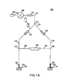
FIG. 1A is a diagram of a gas gauge proximity sensor, according to an
embodiment of the present invention.
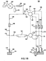
FIG. 1B is a diagram of a gas gauge proximity sensor with multiple
measurement branches, according to an embodiment of the present invention.
FIG. 2 is a diagram that provides a cross sectional view of a restrictor,
according to an embodiment of the present invention.
FIG. 3A is a diagram that shows the basic characteristics of a nozzle.
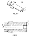
FIG. 3B is a diagram that shows a perspective view of a nozzle that
may be used in a reference probe or a measurement probe, according to an
embodiment of the present invention.
FIG. 3C is a diagram that shows a cross sectional view of the nozzle
illustrated in FIG. 3B, according to an embodiment of the present invention.
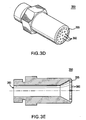
FIG. 3D is a diagram that shows a perspective view of a shower-head
nozzle that may be used in a reference probe or a measurement probe,
according to an embodiment of the present invention.
FIG. 3E is a diagram that shows a cross sectional view of the nozzle
illustrated in FIG 3D, according to an embodiment of the present invention.
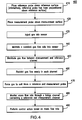
FIG. 4 is a flowchart diagram that shows a method for using a gas
gauge proximity sensor to detect very small distances and perform a control
action, according to an embodiment of the present invention.
FIG. 5 is a sensitivity plot that illustrates test results for nozzles with
different dimensions, according to an embodiment of the present invention.
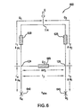
FIG. 6 is a schematic diagram of a gas gauge proximity sensor in a
bridge configuration according to an embodiment of the present invention
whose operation is simulated by a one-dimensional model.
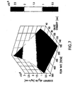
FIG. 7 is a sensitivity plot that illustrates simulation results as a
function of air mass flow rate and gauge nozzle standoff.
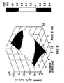
FIG. 8 is a sensitivity plot that illustrates simulation results as a
function of nozzle inner diameter (ID) and length of the porous restrictors.
DETAILED DESCRIPTION OF THE INVENTION
While the present invention is described herein with reference to
illustrative embodiments for particular applications, it should be understood
that the invention is not limited thereto. Those skilled in the art with access to
the teachings provided herein will recognize additional modifications,
applications, and embodiments within the scope thereof and additional fields
in which the present invention would be of significant utility.
| TABLE OF CONTENTS |
| A. | Gas Gauge Proximity Sensor |
| | 1. | Flow Restrictors |
| | 2. | Snubber |
| | 3. | Nozzles |
| B. | Methods |
| C. | Model and Simulation Results |
| | 1. | Selection of Simulation Parameters |
| | 2. | Results |
| D. | Conclusion |
FIG. 1A illustrates gas gauge proximity sensor 100, according to an
embodiment of the present invention. Gas gauge proximity sensor 100
includes mass flow controller 106, central channel 112, measurement channel
116, reference channel 118, measurement channel restrictor 120, reference
channel restrictor 122, measurement probe 128, reference probe 130, bridge
channel 136 and mass flow sensor 138. Gas supply 102 injects gas at a
desired pressure into gas gauge proximity sensor 100.
Central channel 112 connects gas supply 102 to mass flow controller
106 and then terminates at junction 114. Mass flow controller 106 maintains a
constant flow rate within gas gauge proximity sensor 100. Gas is forced out
from mass flow controller 106 through a porous snubber 110, with an
accumulator 108 affixed to channel 112. Snubber 110 reduces gas turbulence
introduced by the gas supply 102, and its use is optional. Upon exiting
snubber 110, gas travels through central channel 112 to junction 114. Central
channel 112 terminates at junction 114 and divides into measurement channel
116 and reference channel 118. Mass flow controller 106 injects gas at a
sufficiently low rate to provide laminar and incompressible fluid flow
throughout the system to minimize the production of undesired pneumatic
noise.
Bridge channel 136 is coupled between measurement channel 116 and
reference channel 118. Bridge channel 136 connects to measurement channel
116 at junction 124. Bridge channel 136 connects to reference channel 118 at
junction 126. In one example, the distance between junction 114 and junction
124 and the distance between junction 114 and junction 126 are equal.
All channels within gas gauge proximity sensor 100 permit gas to flow
through them. Channels 112, 116, 118, and 136 can be made up of conduits
(tubes, pipes, etc.) or any other type of structure that can contain and guide gas
flow through sensor 100. The channels do not have sharp bends, irregularities
or unnecessary obstructions that may introduce pneumatic noise, for example,
by producing local turbulence or flow instability. The overall lengths of
measurement channel 116 and reference channel 118 can be equal or in other
examples can be unequal.
Reference channel 118 terminates into reference probe 130. Likewise,
measurement channel 116 terminates into measurement probe 128. Reference
probe 130 is positioned above reference surface 134. Measurement probe 128
is positioned above measurement surface 132. In the context of
photolithography, measurement surface 132 is often a semiconductor wafer or
stage supporting a wafer. Reference surface 134 can be a flat metal plate, but
is not limited to this example. Gas injected by gas supply 102 is emitted from
each of the probes 128, 130 and impinges upon measurement surface 132 and
reference surface 134. Nozzles are provided in measurement probe 128 and
reference probe 130. Example nozzles are described further below with
respect to FIGs. 3A-3E. As stated above, the distance between a nozzle and a
corresponding measurement or reference surface is referred to as a standoff.
In one embodiment, reference probe 130 is positioned above a fixed
reference surface 134 with a known reference standoff 142. Measurement
probe 128 is positioned above measurement surface 132 with an unknown
measurement standoff 140. The known reference standoff 142 is set to a
desired constant value representing an optimum standoff. With such an
arrangement, the backpressure upstream of the measurement probe 128 is a
function of the unknown measurement standoff 140; and the backpressure
upstream of the reference probe 130 is a function of the known reference
standoff 142. If standoffs 140 and 142 are equal, the configuration is
symmetrical and the bridge is balanced. Consequently, there is no gas flow
through bridging channel 136. On the other hand, when the measurement
standoff 140 and reference standoff 142 are different, the resulting pressure
difference between the measurement channel 116 and the reference channel
118 induces a flow of gas through mass flow sensor 138.
Mass flow sensor 138 is located along bridge channel 136, preferably
at a central point. Mass flow sensor 136 senses gas flows induced by pressure
differences between measurement channel 116 and reference channel 118.
These pressure differences occur as a result of changes in the vertical
positioning of measurement surface 132. For a symmetric bridge, when
measurement standoff 140 and reference standoff 142 are equal, the standoff is
the same for both of the probes 128, 130 compared to surfaces 132, 134. Mass
flow sensor 138 will detect no mass flow, since there will be no pressure
difference between the measurement and reference channels. Differences
between measurement standoff 140 and reference standoff 142 will lead to
different pressures in measurement channel 116 and reference channel 118.
Proper offsets can be introduced for an asymmetric arrangement.
Mass flow sensor 138 senses gas flow induced by a pressure difference
or imbalance. A pressure difference causes a gas flow, the rate of which is a
unique function of the measurement standoff 140. In other words, assuming a
constant flow rate into gas gauge 100, the difference between gas pressures in
the measurement channel 116 and the reference channel 118 is a function of
the difference between the magnitudes of standoffs 140 and 142. If reference
standoff 142 is set to a known standoff, the difference between gas pressures
in the measurement channel 116 and the reference channel 118 is a function of
the size of measurement standoff 140 (that is, the unknown standoff in the z
direction between measurement surface 132 and measurement probe 128).
Mass flow sensor 138 detects gas flow in either direction through
bridge channel 136. Because of the bridge configuration, gas flow occurs
through bridge channel 136 only when pressure differences between channels
116, 118 occur. When a pressure imbalance exists, mass flow sensor 138
detects a resulting gas flow, and can initiate an appropriate control function.
Mass flow sensor 138 can provide an indication of a sensed flow through a
visual display or audio indication. Alternatively, in place of a mass flow
sensor, a differential pressure sensor may be used. The differential pressure
sensor measures the difference in pressure between the two channels, which is
a function of the difference between the measurement and reference standoffs.
The control function may be to calculate the exact gap differences. In
another embodiment, the control function may be to increase or decrease the
size of measurement gap 140. This is accomplished by moving the
measurement surface 132 relative to measurement probe 128 until the pressure
difference is sufficiently close to zero, which occurs when there is no longer a
difference between the standoffs from measurement surface 132 and reference
surface 134.
FIG. 1A illustrates at least three elements of the present invention that
reduce gas turbulence and other pneumatic noise to enable the present
invention to achieve nanometer accuracy. These elements, mass flow rate
controller 106, snubber 110 and restrictors 120, 122, may all be used within an
embodiment of the present invention or in any combination depending on the
sensitivity desired. For example, if an application required very precise
sensitivity, all elements may be used. Alternatively, if an application required
less sensitivity, perhaps only snubber 110 would be needed with porous
restrictors 120 and 122 replaced by orifices. As a result, the present invention
provides a flexible approach to cost effectively meet a particular application's
requirements.
According to further embodiments of the present invention, the
addition of mass flow rate controller 106 and/or snubber 110 may be used
within the systems disclosed in U.S. Patents 4,953,388 and 4,550,592 to
significantly enhance their sensitivity.
FIG. 1B illustrates gas gauge proximity sensor 150, according to an
embodiment of the present invention. Gas gauge proximity sensor 150
includes many of the same components as gas gauge proximity sensor 100
with similar principles of operation. The difference between the two sensors
is that gas gauge proximity sensor 150 has three measurement branches which
are comparable to the one measurement channel included within gas gauge
proximity sensor 100. Three measurement branches are shown for ease of
illustration, and the present invention is not limited to three measurement
branches. Any number of measurement branches from two or more may be
used.
Gas gauge proximity sensor 150 includes mass flow controller 153,
central channel 156, reference channel 158, reference channel restrictor 166,
reference probe 174, bridge channel 190 and mass flow sensor 192. In
addition, gas gauge proximity sensor 150 includes measurement channel 159.
Measurement channel 159 divides into three measurement branches 163, 164
and 165. Measurement branch 163 includes measurement branch restrictor
167 and measurement probe 175. Measurement branch 164 includes
measurement branch restrictor 168 and measurement probe 176.
Measurement branch 165 includes measurement branch restrictor 169 and
measurement probe 177. Finally, gas gauge proximity sensor 150 includes
measurement channel switching device 160, bridge channel switching device
161, and switching device lever 162.
Gas supply 151 injects gas at a desired pressure into gas gauge
proximity sensor 150. Central channel 156 connects gas supply 151 to mass
flow controller 153 and then terminates at a junction 157. Mass flow
controller 153 maintains a constant flow rate within gas gauge proximity
sensor 150. Mass flow controller 153 injects gas at a sufficiently low rate to
provide laminar and incompressible fluid flow throughout the system to
minimize the production of undesired pneumatic noise. Gas is forced out from
mass flow controller 153 through porous snubber 155, with accumulator 154
affixed to channel 156. Snubber 155 reduces gas turbulence introduced by the
gas supply 151, and its use is optional. Upon exiting snubber 155, gas travels
through central channel 156 to junction 157. Central channel 156 terminates at
junction 157 and divides into measurement channel 159 and reference channel
158.
Measurement channel 159 terminates into measurement channel
switching device 160. Measurement channel switching device 160 can be a
scanning valve or other type of switching device that serves to switch a
measurement channel to one of several measurement branches that are also
connected to measurement channel switching device 160. The physical
characteristics of a measurement branch are the same as the physical
characteristics of a measurement channel. Measurement channel switching
device 160 is operated by switching device lever 162. Switching device lever
162 controls which measurement branch 163, 164 or 165 is connected to the
measurement channel 159 through measurement channel switching device
160.
Bridge channel 190 is coupled between reference channel 158 and one
of the three measurement branches 163, 164 or 165 through bridge channel
switching device 161. Bridge channel 190 connects to reference channel 158
at junction 170. Bridge channel 190 terminates in bridge channel switching
device 161. Bridge channel switching device 161 can be a scanning valve or
other type of switching device that serves to switch a bridge channel to one of
the measurement branches. In one example shown in FIG 1B, three
measurement branches 163, 164 and 165 are connected to bridge channel
switching device 161 at junctions 171, 172, and 173 respectively. Switching
device lever 162 controls which measurement branch 163, 164, or 165 is
connected to the bridge channel through bridge channel switching device 161.
Switching lever 162 controls both measurement channel switching device 160
and bridge channel switching device 161, such that the same measurement
branch will be connected to both measurement channel 159 and bridge
channel 190. Alternatively, two independent switching levers can be used.
In one example, the distance between junction 157 and junction 170
and the distance between junction 157 and junction 171, 172 or 173 are equal.
All channels and branches within gas gauge proximity sensor 150
permit gas to flow through them. Channels 156, 158, 159, and 190, and
branches 163, 164, and 165 can be made up of conduits (tubes, pipes, etc.) or
any other type of structure that can contain and guide gas flow through sensor
150. The channels and branches do not have sharp bends, irregularities or
unnecessary obstructions that may introduce pneumatic noise, for example, by
producing local turbulence or flow instability. The overall lengths of
reference channel 158 and measurement channel 159 plus one of
measurement branches 163, 164 or 165 can be equal or in other examples can
be unequal.
Reference channel 158 terminates into reference probe 174. Likewise,
measurement branches 163, 164 and 165 terminate into measurement probes
175, 176 and 177 respectively. Reference probe 174 is positioned above
reference surface 178. Measurement probes 175, 176 and 177 are positioned
above measurement surface 179. In the context of photolithography,
measurement surface 179 is often a semiconductor wafer or stage supporting a
wafer. Reference surface 178 can be a flat metal plate, but is not limited to
this example. Gas injected by gas supply 151 is emitted from reference probe
174 and impinges upon reference surface 178. Likewise, gas injected by gas
supply 151 is emitted from one of the three measurement probes 175, 176 or
177 and impinges on measurement surface 179. The position of switching
device lever 162 determines from which measurement probe gas is emitted.
Nozzles are provided in probes 174, 175, 176 and 177. Example nozzles are
described further below with respect to FIGs. 3A-3E. As stated above, the
distance between a nozzle and a corresponding measurement or reference
surface is referred to as a standoff.
In one embodiment, reference probe 174 is positioned above a fixed
reference surface 178 with a known reference standoff 180. Measurement
probes 175, 176 and 177 are positioned above measurement surface 179 with
unknown measurement standoffs 181, 182 and 183. Measurement standoffs
181, 182 and 183 may be equal or they may be unequal where the topography
of a measurement surface varies from region to region. The known reference
standoff 180 is set to a desired constant value representing an optimum
standoff. With such an arrangement, the backpressure upstream from
measurement probe 175, 176 or 177 that is in use is a function of the unknown
measurement standoff 181, 182 or 183 respectively; and the backpressure
upstream of the reference probe 174 is a function of the known reference
standoff 180. If reference standoff 180 and the measurement standoff 181,
182 or 183 that is being used are equal, the configuration is symmetrical and
the bridge is balanced. Consequently, there is no gas flow through bridge
channel 174. On the other hand, when the reference standoff 180 and the
measurement standoff 181, 182 or 183 corresponding to the measurement
branch in use is different, the resulting pressure difference between the
reference channel 158 and the measurement branch 163, 164 or 165 that is
being used induces a flow of gas through bridge channel 190.
Mass flow sensor 192 is located along bridge channel 190, preferably
at a central point. Mass flow sensor 192 senses gas flows induced by pressure
differences between reference channel 158 and the measurement branch 163,
164 or 165 that is being used. These pressure differences occur as a result of
changes in the vertical positioning of measurement surface 179. For a
symmetric bridge, when reference standoff 180 and a measurement standoff
181, 182 or 183 corresponding to the measurement branch that is being used
are equal, mass flow sensor 192 will detect no mass flow, since there will be
no pressure difference between the measurement branch in use and the
reference channel. Differences between the reference standoff 180 and a
measurement standoff 181, 182 or 183 corresponding to the measurement
branch in use will lead to different pressures in reference channel 158 and the
measurement branch 163, 164 or 165 being used. Proper offsets can be
introduced for an asymmetric arrangement.
Mass flow sensor 192 senses gas flow induced by a pressure difference
or imbalance. A pressure difference causes a gas flow, the rate of which is a
unique function of a measurement standoff 181, 182 or 183. In other words,
assuming a constant flow rate into gas gauge 150, the difference between gas
pressures in a measurement branch 163, 164 or 165 and reference channel 158
is a function of the difference between reference standoff 180 and a
measurement standoff 181, 182 or 183 corresponding to the measurement
branch that is being used. If reference standoff 180 is set to a known standoff,
the difference between gas pressures in a measurement branch 163, 164 or 165
that is being used and reference channel 158 is a function of the size of a
measurement standoff (that is, the unknown standoff in the z direction
between measurement surface 179 and a measurement probe 175, 176 or 177
that is being used).
Mass flow sensor 192 detects gas flow in either direction through
bridge channel 190. Because of the bridge configuration, gas flow occurs
through bridge channel 190 only when pressure differences occur between
reference channel 158 and a measurement branch 163, 164 or 165 that is being
used. When a pressure imbalance exists, mass flow sensor 192 detects a
resulting gas flow, and can initiate an appropriate control function. Mass flow
sensor 192 can provide an indication of a sensed flow through a visual display
or audio indication. Alternatively, in place of a mass flow sensor, a differential
pressure sensor may be used. The differential pressure sensor measures the
difference in pressure between the reference channel and a measurement
branch, which is a function of the difference between a measurement standoff
and the reference standoff.
The control function may be to calculate the exact gap differences. In
another embodiment, the control function may be to increase or decrease the
size of a measurement standoff 181, 182 or 183. This is accomplished by
moving the measurement surface relative to a measurement probe until the
pressure difference is sufficiently close to zero, which occurs when there is no
longer a difference between the standoffs from a measurement surface and
reference surface 178.
FIG. 1B illustrates at least three elements of the present invention that
reduce gas turbulence and other pneumatic noise to enable the present
invention to achieve nanometer accuracy. These elements, mass flow rate
controller 153, snubber 155 and restrictors 166, 167, 168 and 169 may all be
used within an embodiment of the present invention or in any combination
depending on the sensitivity desired. For example, if an application required
very precise sensitivity, all elements may be used. Alternatively, if an
application required less sensitivity, perhaps only snubber 155 would be
needed with porous restrictors 166, 167, 168, and 169 replaced by orifices. As
a result, the present invention provides a flexible approach to cost effectively
meet a particular application's requirements.
1. Flow Restrictors
According to one embodiment of the present invention and referring to
gas gauge proximity sensor 100, measurement channel 116 and reference
channel 118 contain restrictors 120, 122. Each restrictor 120, 122 restricts the
flow of gas traveling through the respective measurement channel 116 and
reference channel 118. Measurement channel restrictor 120 is located within
measurement channel 116 between junction 114 and junction 124. Likewise,
reference channel restrictor 122 is located within reference channel 118
between junction 114 and junction 126. In one example, the distance from
junction 114 to measurement channel restrictor 120 and the distance from
junction 114 to reference channel restrictor 122 are equal. In other examples,
the distances are not equal. There is no inherent requirement that the sensor
be symmetrical, however, the sensor is easier to use if it is geometrically
symmetrical.
According to a further feature of the present invention, each restrictor
120, 122 consists of a porous material, such as polyethylene or sintered
stainless steel. FIG. 2 provides a cross-sectional image of restrictor 120 having
porous material 210 through which a gas flow 200 passes. Measurement
channel restrictor 120 and reference channel restrictor 122 have substantially
the same dimensions and permeability characteristics. Restrictors typically
range in length from 2 to 15mm, but are not limited to these lengths.
Measurement channel restrictor 120 and reference channel restrictor 122
restrict gas flow evenly across the cross-sectional areas of the channels 116,
118. The inventors discovered that porous material restrictors provide a
significant reduction in turbulence and associated pneumatic noise in gas flow
compared to the amount of turbulence and noise introduced by restrictors that
use a single orifice bored out of a solid, non-porous material. Within gas
gauge proximity sensor 150, porous restrictors 166, 167, 168 and 169 with
above mentioned characteristics are also used to achieve these advantages.
The restrictors serve two key functions. First, they mitigate the
pressure and flow disturbances present in gas gauge proximity sensor 100,
most notably disturbances generated by mass flow controller 110 or sources of
acoustic pick-up. Second, they serve as the required resistive elements within
the bridge.
Exemplary embodiments of a gas gauge proximity sensor have been
presented. The present invention is not limited to this example. This example
is presented herein for purposes of illustration, and not limitation.
Alternatives (including equivalents, extensions, variations, deviations, etc., of
those described herein) will be apparent to persons skilled in the relevant art(s)
based on the teachings contained herein. Such alternatives fall within the
scope and spirit of the present invention.
2. Snubber
According to one embodiment of the present invention and referring to
gas gauge proximity sensor 100, channel 112 contains snubber 110. Similar to
the operation of a restrictor, snubber 110 reduces gas turbulence introduced by
gas supply 102 and isolates the mass flow sensor from acoustic pick-up in the
upstream part of the gas gauge sensor. Snubber 110 is located within channel
112 between accumulator 108 and junction 114. According to a further
feature of the present invention, snubber 110 consists of a porous material,
such as polyethylene or sintered stainless steel. The inventors discovered that
porous material snubbers provide a significant reduction in turbulence and
associated pneumatic noise in gas flow. Snubber 155 used within gas gauge
proximity sensor 150 has the same characteristics as Snubber 110 and is used
to achieve the same benefits.
3. Nozzles
In gas gauge proximity sensor 100, different types of nozzles may be
used as reference probe 130 and measurement probe 128 depending on a
particular application. Similarly different types of nozzles may be used in gas
gauge proximity sensor 150 for reference probe 174 and measurement probes
181, 182 and 183. The choice of nozzle type, among other things, depends on
the footprint (measurement area) that is required.
The basic configuration of the gas gauge nozzle 300 is characterized
by a flat end surface that is parallel to the surface of the measurement surface,
as shown in FIG. 3A. The geometry of a nozzle is determined by the gauge
standoff, h, and the inner diameter, d. Generally, the dependence of the nozzle
pressure drop on the nozzle outer diameter D is weak, if D is sufficiently large.
The remaining physical parameters are: Qm - mass flow rate of the gas, and Δp
- pressure drop across the nozzle. The gas is characterized by the density, ρ,
and dynamic viscosity, η.
A relationship is sought between non-dimensional parameters:
Δp 12 ρu 2 ,
the Reynolds Number, Re, and h / d, where the radial velocity, u, is taken at the
entrance to the cylindrical region between the nozzle face and the wafer
surface. The Reynolds number is defined as Re = ud / ν, where ν is the
kinematic coefficient of viscosity.
A series of tests where the measurement standoff was varied were
performed using nozzles with different d and using different mass flow rates.
FIG. 5 plots the data points for these tests. A suitable fit to data points
obtained from the series of measurements that are shown in FIG. 5 yields:
Δp ρ u 2 2 ud ν = 78.493 h d -1.3114
Since the mass flow rate of air through the nozzle can be written as:
Qm = ρu πdh
expressing the velocity u in terms of the mass flow rate Qm and inner nozzle
diameter d yields :
Δp ≅ 78.4932π ·Qm ν h -2.3114 d -0.6886.
The behavior of the nozzle is then described in terms of five physical
variables: ν, Δp, Qm , d, and h. Eq. (3) provides a relationship between the two
principal variables, Δp and h, as the remaining variables would be typically
constant for a practical system. This relationship facilitates the development
of nozzle types for different applications, requiring different sensitivities.
FIGS. 3B and 3C illustrate a nozzle 310 that may be used as a
reference probe or measurement probe, according to an embodiment of the
present invention. Nozzle 310 includes front surface 312, gas bore front
opening 314, and gas bore rear opening 315.
Nozzle 310 is affixed to both measurement channel 116 and reference
channel 118. In one embodiment, two identical nozzles 310 serve as
measurement probe 128 and reference probe 130. In principle, the nozzles do
not need to be identical. Nozzle 310 is affixed to measurement channel 116.
Front surface 312 should be parallel to measurement surface 132. Gas
travelling through measurement channel 116 enters nozzle 310 through gas
bore rear opening 315 and exits through gas bore front opening 314.
Similarly, nozzle 310 is affixed to reference channel 118. Front surface 312 is
parallel to reference surface 134. Gas travelling through reference channel 118
enters nozzle 310 through gas bore rear opening 315 and exits through gas
bore front opening 314. The diameter of gas bore front opening 314 can vary
depending upon a particular application. In one example, the inner diameter
of gas bore front opening 314 is between approximately 0.5 and 2.5
millimeters (mm). Example sensitivity analysis results of a gas gauge
proximity sensor model having porous flow restrictors and single gas bore
nozzles at the probes are described further below with respect to FIGs. 6-8.
FIGS. 3D and 3E illustrate shower-head nozzle 350 that may be used
as the reference and measurement probes, according to an embodiment of the
present invention. Shower-head nozzle 350 includes front surface 355, a
plurality of gas bore front openings 360, and a gas bore rear opening 365. The
multiple gas bore front openings distribute pressure across a wider area of
measurement surface 132 than nozzle 310. A shower-head nozzle is
principally used for lowering spatial resolution to evenly integrate proximity
measurements over a wider spatial area. An alternative approach would be to
use a nozzle that contains a porous filter.
A shower-head nozzle 350 is affixed to both measurement channel 116
and reference channel 118. In one embodiment, two identical shower-head
nozzles 350 serve as measurement probe 128 and reference probe 130. In
principle, the nozzles do not need to be identical. Shower-head nozzle 350 is
affixed to measurement channel 116. Front surface 355 is parallel to
measurement surface 132. Gas travelling through measurement channel 116
enters shower-head nozzle 350 through gas bore rear opening 365 and exits
through a plurality of gas bore front openings 360. Similarly, shower-head
nozzle 350 is affixed to reference channel 118. Front surface 355 is parallel to
reference surface 134. Gas travelling through reference channel 122 enters
shower-head nozzle 350 through gas bore rear opening 365 and exits through a
plurality of gas bore front openings 360. The use of nozzles has been
explained with reference to gas gauge proximity sensor 100 for ease of
illustration. Each of the nozzle types may also be used with gas gauge
proximity sensor 150, wherein the nozzles would be affixed to each of the
measurement branch probes and the reference channel probe.
Exemplary embodiments of different types of nozzles have been
presented. The present invention is not limited to these examples. The
examples are presented herein for purposes of illustration, and not limitation.
Alternatives (including equivalents, extensions, variations, deviations, etc., of
those described herein) will be apparent to persons skilled in the relevant art(s)
based on the teachings contained herein. Such alternatives fall within the
scope and spirit of the present invention.
B. Methods
The process illustrated in FIG. 4 presents a method 400 for using gas
flow to detect very small distances and perform a control action (steps 410-470).
For convenience, method 400 is described with respect to gas gauge
proximity sensor 100. However, method 400 is not necessarily limited by the
structure of sensor 100, and can be implemented with gas gauge proximity
sensor 150 or a sensor with a different structure.
The process begins in step 410. In step 410, an operator or mechanical
device places a reference probe above a reference surface. For example, an
operator or mechanical device positions reference probe 130 above reference
surface 134 with known reference standoff 142. Alternatively, the reference
standoff can be arranged within the sensor assembly, that is, internal to the
sensor assembly. The reference standoff is pre-adjusted to a particular value,
which typically would be maintained constant. In step 420, an operator or
mechanical device places a measurement probe above a measurement surface.
For example, an operator or mechanical device positions measurement probe
128 above measurement surface 132 to form measurement gap 140.
In step 430, gas is injected into a sensor. For example, a measurement
gas is injected into gas gauge proximity sensor 100 with a constant mass flow
rate. In step 440, a constant gas flow rate into a sensor is maintained. For
example, mass flow controller 106 maintains a constant gas flow rate. In step
450, gas flow is distributed between measurement and reference channels. For
example, gas gauge proximity sensor 100 causes the flow of the measurement
gas to be evenly distributed between measurement channel 116 and reference
channel 118.
In step 460, gas flow in the measurement channel and the reference
channel is restricted evenly across cross-sectional areas of the channels.
Measurement channel restrictor 120 and reference channel restrictor 122
restrict the flow of gas to reduce pneumatic noise and serve as a resistive
element in gas gauge proximity sensor 100.
In step 470, gas is forced to exit from a reference and measurement
probe. For example, gas gauge proximity sensor 100 forces gas to exit
measurement probe 128 and reference probe 130. In step 480, a flow of gas is
monitored through a bridge channel connecting a reference channel and a
measurement channel. In step 490, a control action is performed based on a
pressure difference between the reference and measurement channel. For
example, mass flow sensor 138 monitors mass flow rate between measurement
channel 116 and reference channel 118. Based on the mass flow rate, mass
flow sensor 138 initiates a control action. Such control action may include
providing an indication of the sensed mass flow, sending a message indicating
a sensed mass flow, or initiating a servo control action to reposition the
location of the measurement surface relative to the reference surface until no
mass flow or a fixed reference value of mass flow is sensed.
The above method may be adapted to use with a sensor that has
multiple measurement branches, such as gas gauge proximity sensor 150.
When gas gauge proximity sensor 150 is used, an additional step may be
incorporated that includes switching from the use of one measurement branch
to another measurement branch.
The use of a gas gauge proximity sensor 150 can also better facilitate
the mapping of the topography of a mesurement surface. This mapping may
be accomplished through the principles described in the above method,
wherein topography measurements are taken over a particular region of a work
surface using one of the measurement branches. If a topography mapping is
desired of a different region, the flow of gas may be switched to a different
measurement branch to map the topography of a different region. Because of
limitations that may exist in the ability to move a measurement surface, a
proximity sensor with multiple branches can be used in some instances to
more readily map the topography of a measurement surface than a proximity
sensor with only one measurement channel.
For example, in one embodiment a method for mapping the
topography includes injecting gas into a proximity sensor, such as gas gauge
proximity sensor 150, and measuring the topography of a region of a
measurement surface by taking a series of measurements using one of the
measurement branches. Upon completing the mapping of the region that can
be mapped by a particular measurement branch, the proximity sensor would be
switched to a different measurement branch to repeat the mapping process for
the region reached by that measurement branch. The process would be
repeated until the surface for which a topography mapping is desired is
completed. The measurement surface may be a semiconductor wafer or other
measurement surface for which a topography mapping is desired.
Additional steps or enhancements to the above steps known to person
skilled in the relevant art(s) form the teachings herein are also encompassed by
the present invention.
The present invention has been described with respect to FIGs. 1-4
with reference to a gas. In one embodiment the gas is air. The present
invention is not limited to air. Other gases or combinations of gases can be
used. For example, depending on the surface being measured, a gas having a
reduced moisture content or an inert gas may be used. A low moisture content
gas or inert gas is less likely than air to react with the surface being measured.
C. Model and Simulation Results
The inventors developed a one-dimensional (1-D) model to simulate
operation of a gas gauge proximity sensor ("gas gauge") in a bridge
configuration according to an embodiment of the present invention for which a
prototype was built. Fig. 6 is a schematic diagram of a gas gauge proximity
sensor 600 (also referred to as a "bridge" 600) whose operation is described
with respect to the one-dimensional model. As shown in FIG. 6, gas gauge
600 includes five legs l1 - l5, two porous flow restrictors 630, 635,
measurement nozzle 640, reference nozzle 645, and a mass flow sensor 665.
Leg l1 extends from junction 114 to junction 124. Leg l2 extends from
junction 114 to junction 126. Leg 13 extends between junctions 124 and 126.
Leg l4 extends from junction 124 to measurement nozzle 640. Leg l5 extends
from junction 126 to reference nozzle 645. Porous flow restrictor 630 is
provided along leg l1. Porous flow restrictor 635 is provided along leg l2.
Measurement nozzle 640 is provided at the end of leg l4. Reference nozzle
645 is provided at the end of leg l5. Mass flow sensor 665 is provided along
leg l3.
The 1-D model of the gas gauge aids the development process of the
gas gauge. The model allows for a selection of the gas gauge physical
parameters and yields a quick assessment of the gas gauge performance under
steady state operation.
It is assumed that all the gas passages of bridge 600 have circular
cross-section with the same diameter. The most significant contribution to
pressure drop in the legs of the bridge is from flow restrictors 630, 635 and
nozzles 640, 645, however a distributed contribution from viscous loses in the
tubes of legs 11-15 is considered. Local losses at elbows and junctions 114,
124, 126 are neglected, as they are relatively small.
With these assumptions, steady incompressible flow of gas through
bridge 600, as shown in Figure 6, is governed by the following set of algebraic
equations:
Q = Q 1 + Q 2 ,
Q 4 = Q 1 + Q 3 ,
Q 5 = Q 2 - Q 3 ,
Δp 1 = Δp 2 + Δp 3 ,
Δp 5 = Δp 4 + Δp 3 ,
Δpi = fi (Qi ), i = 1,...,5
Balancing the flow rates Qi in the junctions of the bridge results in
equations (4-6), while balancing the values of pressure drop Δpi across the legs
in the loops of the bridge yields equations (7) and (8). Equations (9) define
relationships between the flow rate Q and the pressure drop Δp across each of
the legs (i=1..5).
The pressure drop for the upper legs, l1 and l2, is a sum of viscous
loses in the tubes and (also viscous) loses in the porous restrictors:
Δpi = λ i li di ρ wi 2 2 +µ K lRiwi i=1,2 ,
where li and di are the tube length and diameter, while wi is the (cross-section
averaged) velocity in the leg i. For laminar pipe flow the pressure loss
coefficient is a function of the Reynolds number alone:
λ=64Re .
The pressure loss in a porous restrictor is modeled after Darcy's law.
See, A. Bejan,
Convective Heat Transfer, Chapter 10 John Wiley & Sons,
1984. The restrictors 630, 635 are of the length
lR and have the same diameter
as the tube in legs l1 and l2 that results in the same averaged velocity
wi . The
constants µ and
K are the dynamic viscosity of fluid (air) and the permeability
of the porous material, correspondingly. The pressure drop can be expressed in
terms of the mass flow rate
Qi . Substituting for the velocity
wi ,
wi = 4Qi π d 2 i
yields
with the constants
A and
C:
A=128v π , C=4Θπρ .
ν and p are the kinematic viscosity and density of the gas (air),
correspondingly, and Θ is the conductivity of porous material.
The pressure drop in the bridging leg l3 is modeled simply as:
Δp 3 = aQ 3,
because the actual behavior of the mass flow sensor is linear at sufficient level
of approximation. The coefficient a was determined experimentally showing
good agreement with technical specifications of the mass flow meter.
The pressure drop for legs
l4 and
l5 is modeled as a sum of viscous
loses in the tube (similarly as for legs
l1 and
l2) and the losses in the nozzles:
Δpi = λ i li di ρ w i 2 2 +ρu i 2 2 78.493 uiD ν hi D -1.3114 i = 4,5 ,
The second component of the sum in equation (16) represents a semi-empirical,
similarity-based model for the pressure drop across a nozzle.
Variable
ui denotes the area-averaged value of the radial velocity at the
entrance to the annular region between the surface of a wafer and the face of
the of the air gauge nozzle. This velocity can be calculated as
ui = Qi π D hi i=4,5 ,
where
D is the inner diameter (ID) of the nozzle (both nozzles 640, 645 are
identical) and
hi is the gauge standoff. Making appropriate substitutions
yields:
The system of ten equations (4-8,13,15,18) is linear with respect to the
flow rates Qi . Validity of the laminar flow assumption was confirmed by
calculating Reynold's Numbers for the respective sections of the entire
system. A Matlab program can be used to numerically solve the above
equations for a given set of input parameters.
1. Selection of Simulation Parameters
Main parameters for the simulation were selected to match a working
prototype of gauges 100, 600 with air as the gas. The main parameters are
summarized below.
| Properties of air: |
| density | ρ =1.2003 | [kg/m3] |
| dynamic viscosity | µ =1.8189 E-05 | [kg/(ms)] |
| kinematic viscosity | ν =1.5157 E-05 | [m2/s] |
| Properties of porous material: |
| porous conductivity | Θ =4327 E02 | [kg/(sm3)] |
| Flowmeter response (linear): |
| calibration constant | a=1144 E04 | [1/(ms)] |
| Air gauge geometric parameters: |
| Leg # | 1 | 2 | 3 | 4 | 5 |
| Diameter [mm] | 3.37 | 3.37 | - | 3.37 | 3.37 |
| Length [mm] | 38.1 | 101.6 | - | 70.9 | 32.4 |
| Porous insert length [mm] | 7.0 | 7.0 | - | - | - |
Results of the simulation are shown in terms of sensitivity plots as a
function of the mass flow rate and the gauge nozzle standoff (FIG. 7) and as a
function of the nozzle ID and the length of the porous restrictors (FIG. 8).
Specifically, FIG. 7 illustrates a sensitivity plot as a function of the
mass flow rate and gauge nozzle standoff for a gauge with a nozzle having a
1.14mm internal diameter (ID) and a restrictor that is 7 mm in length. To
generate the plot, gauge standoffs ranging from 40 to 140mm were used and
flow rates ranging from 100 to 500 sccm. The plot shows that as the gauge
standoff becomes smaller, the sensitivity of the gauge to detect changes in the
difference between a reference standoff and a measurement standoff increases.
The plot shows that the rate of sensitivity increase as the gauge standoff
becomes smaller is more pronounced at higher flow rates. Similarly, for a
constant gauge standoff, as the flow rate of gas through the gauge increases,
the sensitivity also increases.
FIG. 8 illustrates a sensitivity plot as a function of the nozzle ID and
restrictor length when the measurement standoff is 100mm and the flow rate is
200 sccm. To generate the plot, nozzles with IDs ranging from 0.5 to 2.5mm
were used and restrictors with lengths ranging from 5 to 15mm were used. The
plot shows that as the nozzle ID becomes smaller, the sensitivity of the gauge
to detect changes in the difference between a reference standoff and a
measurement standoff increases. The plot further shows that the rate of
sensitivity increase as the nozzle ID becomes smaller, remains relatively
consistent over the different restrictor lengths. Finally, the plot illustrates a
relatively small dependence of the gauge sensitivity on the length of both
restrictors.
As can be seen from FIG. 7 and FIG. 8, the sensitivity dependence on
the flow rate and the standoff is relatively major. It increases (linearly) with
the flow rate and decreases with the standoff at a faster than linear rate. The
sensitivity dependence on the two other parameters (nozzle ID and the
restrictor length) is considerably weaker within practical limits of the
variability of these parameters. It decreases with the ID of the nozzle and
increases with the restrictor length. The data show that the increasing the flow
rate can be used to improve the gauge sensitivity as long as this would not
cause an increase in the aerodynamic noise. Transition to turbulence would
certainly be a practical limitation on the maximum flow rate that can be used.
D. Conclusion
While various embodiments of the present invention have been
described above, it should be understood that they have been presented by way
of example, and not limitation. It will be apparent to persons skilled in the
relevant art that various changes in form and detail can be made therein
without departing from the spirit and scope of the invention.
The present invention has been described above with the aid of method
steps illustrating the performance of specified functions and relationships
thereof. The boundaries of these method steps have been arbitrarily defined
herein for the convenience of the description. Alternate boundaries can be
defined so long as the specified functions and relationships thereof are
appropriately performed. Any such alternate boundaries are thus within the
scope and spirit of the claimed invention. Thus, the breadth and scope of the
present invention should not be limited by any of the above-described
exemplary embodiments, but should be defined only in accordance with the
following claims and their equivalents.