EP1439050A1 - Beschichtereinrichtung für eine Bauvorrichtung zur Erstellung von Formteilen aus Pulvermaterial - Google Patents
Beschichtereinrichtung für eine Bauvorrichtung zur Erstellung von Formteilen aus Pulvermaterial Download PDFInfo
- Publication number
- EP1439050A1 EP1439050A1 EP03029510A EP03029510A EP1439050A1 EP 1439050 A1 EP1439050 A1 EP 1439050A1 EP 03029510 A EP03029510 A EP 03029510A EP 03029510 A EP03029510 A EP 03029510A EP 1439050 A1 EP1439050 A1 EP 1439050A1
- Authority
- EP
- European Patent Office
- Prior art keywords
- blade
- coater
- coating device
- shear
- blades
- Prior art date
- Legal status (The legal status is an assumption and is not a legal conclusion. Google has not performed a legal analysis and makes no representation as to the accuracy of the status listed.)
- Granted
Links
- 238000000576 coating method Methods 0.000 title claims abstract description 58
- 239000011248 coating agent Substances 0.000 title claims abstract description 44
- 239000000463 material Substances 0.000 title claims abstract description 9
- 239000004566 building material Substances 0.000 claims abstract description 25
- 238000010008 shearing Methods 0.000 claims abstract description 21
- 238000009434 installation Methods 0.000 claims abstract description 11
- 238000003860 storage Methods 0.000 claims abstract description 10
- 230000005855 radiation Effects 0.000 claims abstract description 9
- 238000000034 method Methods 0.000 claims description 20
- 238000010276 construction Methods 0.000 claims description 16
- 238000000149 argon plasma sintering Methods 0.000 claims description 5
- 238000013017 mechanical damping Methods 0.000 claims description 3
- 238000000465 moulding Methods 0.000 abstract description 3
- 238000001459 lithography Methods 0.000 abstract 2
- 239000000843 powder Substances 0.000 description 9
- 230000008901 benefit Effects 0.000 description 4
- 238000005245 sintering Methods 0.000 description 4
- 230000000694 effects Effects 0.000 description 2
- 239000002245 particle Substances 0.000 description 2
- 230000003746 surface roughness Effects 0.000 description 2
- 230000002411 adverse Effects 0.000 description 1
- 238000005520 cutting process Methods 0.000 description 1
- 230000006866 deterioration Effects 0.000 description 1
- 238000009826 distribution Methods 0.000 description 1
- 230000008018 melting Effects 0.000 description 1
- 238000002844 melting Methods 0.000 description 1
- 239000002184 metal Substances 0.000 description 1
- 238000007711 solidification Methods 0.000 description 1
- 230000008023 solidification Effects 0.000 description 1
Images


Classifications
-
- B—PERFORMING OPERATIONS; TRANSPORTING
- B29—WORKING OF PLASTICS; WORKING OF SUBSTANCES IN A PLASTIC STATE IN GENERAL
- B29C—SHAPING OR JOINING OF PLASTICS; SHAPING OF MATERIAL IN A PLASTIC STATE, NOT OTHERWISE PROVIDED FOR; AFTER-TREATMENT OF THE SHAPED PRODUCTS, e.g. REPAIRING
- B29C41/00—Shaping by coating a mould, core or other substrate, i.e. by depositing material and stripping-off the shaped article; Apparatus therefor
- B29C41/34—Component parts, details or accessories; Auxiliary operations
- B29C41/36—Feeding the material on to the mould, core or other substrate
-
- B—PERFORMING OPERATIONS; TRANSPORTING
- B22—CASTING; POWDER METALLURGY
- B22F—WORKING METALLIC POWDER; MANUFACTURE OF ARTICLES FROM METALLIC POWDER; MAKING METALLIC POWDER; APPARATUS OR DEVICES SPECIALLY ADAPTED FOR METALLIC POWDER
- B22F12/00—Apparatus or devices specially adapted for additive manufacturing; Auxiliary means for additive manufacturing; Combinations of additive manufacturing apparatus or devices with other processing apparatus or devices
- B22F12/50—Means for feeding of material, e.g. heads
- B22F12/52—Hoppers
-
- B—PERFORMING OPERATIONS; TRANSPORTING
- B22—CASTING; POWDER METALLURGY
- B22F—WORKING METALLIC POWDER; MANUFACTURE OF ARTICLES FROM METALLIC POWDER; MAKING METALLIC POWDER; APPARATUS OR DEVICES SPECIALLY ADAPTED FOR METALLIC POWDER
- B22F12/00—Apparatus or devices specially adapted for additive manufacturing; Auxiliary means for additive manufacturing; Combinations of additive manufacturing apparatus or devices with other processing apparatus or devices
- B22F12/60—Planarisation devices; Compression devices
- B22F12/67—Blades
-
- B—PERFORMING OPERATIONS; TRANSPORTING
- B22—CASTING; POWDER METALLURGY
- B22F—WORKING METALLIC POWDER; MANUFACTURE OF ARTICLES FROM METALLIC POWDER; MAKING METALLIC POWDER; APPARATUS OR DEVICES SPECIALLY ADAPTED FOR METALLIC POWDER
- B22F3/00—Manufacture of workpieces or articles from metallic powder characterised by the manner of compacting or sintering; Apparatus specially adapted therefor ; Presses and furnaces
- B22F3/004—Filling molds with powder
-
- B—PERFORMING OPERATIONS; TRANSPORTING
- B29—WORKING OF PLASTICS; WORKING OF SUBSTANCES IN A PLASTIC STATE IN GENERAL
- B29C—SHAPING OR JOINING OF PLASTICS; SHAPING OF MATERIAL IN A PLASTIC STATE, NOT OTHERWISE PROVIDED FOR; AFTER-TREATMENT OF THE SHAPED PRODUCTS, e.g. REPAIRING
- B29C41/00—Shaping by coating a mould, core or other substrate, i.e. by depositing material and stripping-off the shaped article; Apparatus therefor
- B29C41/02—Shaping by coating a mould, core or other substrate, i.e. by depositing material and stripping-off the shaped article; Apparatus therefor for making articles of definite length, i.e. discrete articles
- B29C41/12—Spreading-out the material on a substrate, e.g. on the surface of a liquid
-
- B—PERFORMING OPERATIONS; TRANSPORTING
- B29—WORKING OF PLASTICS; WORKING OF SUBSTANCES IN A PLASTIC STATE IN GENERAL
- B29C—SHAPING OR JOINING OF PLASTICS; SHAPING OF MATERIAL IN A PLASTIC STATE, NOT OTHERWISE PROVIDED FOR; AFTER-TREATMENT OF THE SHAPED PRODUCTS, e.g. REPAIRING
- B29C64/00—Additive manufacturing, i.e. manufacturing of three-dimensional [3D] objects by additive deposition, additive agglomeration or additive layering, e.g. by 3D printing, stereolithography or selective laser sintering
- B29C64/10—Processes of additive manufacturing
- B29C64/141—Processes of additive manufacturing using only solid materials
- B29C64/153—Processes of additive manufacturing using only solid materials using layers of powder being selectively joined, e.g. by selective laser sintering or melting
-
- B—PERFORMING OPERATIONS; TRANSPORTING
- B29—WORKING OF PLASTICS; WORKING OF SUBSTANCES IN A PLASTIC STATE IN GENERAL
- B29C—SHAPING OR JOINING OF PLASTICS; SHAPING OF MATERIAL IN A PLASTIC STATE, NOT OTHERWISE PROVIDED FOR; AFTER-TREATMENT OF THE SHAPED PRODUCTS, e.g. REPAIRING
- B29C64/00—Additive manufacturing, i.e. manufacturing of three-dimensional [3D] objects by additive deposition, additive agglomeration or additive layering, e.g. by 3D printing, stereolithography or selective laser sintering
- B29C64/20—Apparatus for additive manufacturing; Details thereof or accessories therefor
- B29C64/205—Means for applying layers
- B29C64/214—Doctor blades
-
- B—PERFORMING OPERATIONS; TRANSPORTING
- B22—CASTING; POWDER METALLURGY
- B22F—WORKING METALLIC POWDER; MANUFACTURE OF ARTICLES FROM METALLIC POWDER; MAKING METALLIC POWDER; APPARATUS OR DEVICES SPECIALLY ADAPTED FOR METALLIC POWDER
- B22F2998/00—Supplementary information concerning processes or compositions relating to powder metallurgy
-
- B—PERFORMING OPERATIONS; TRANSPORTING
- B22—CASTING; POWDER METALLURGY
- B22F—WORKING METALLIC POWDER; MANUFACTURE OF ARTICLES FROM METALLIC POWDER; MAKING METALLIC POWDER; APPARATUS OR DEVICES SPECIALLY ADAPTED FOR METALLIC POWDER
- B22F2999/00—Aspects linked to processes or compositions used in powder metallurgy
-
- B—PERFORMING OPERATIONS; TRANSPORTING
- B29—WORKING OF PLASTICS; WORKING OF SUBSTANCES IN A PLASTIC STATE IN GENERAL
- B29C—SHAPING OR JOINING OF PLASTICS; SHAPING OF MATERIAL IN A PLASTIC STATE, NOT OTHERWISE PROVIDED FOR; AFTER-TREATMENT OF THE SHAPED PRODUCTS, e.g. REPAIRING
- B29C37/00—Component parts, details, accessories or auxiliary operations, not covered by group B29C33/00 or B29C35/00
- B29C37/02—Deburring or deflashing
-
- Y—GENERAL TAGGING OF NEW TECHNOLOGICAL DEVELOPMENTS; GENERAL TAGGING OF CROSS-SECTIONAL TECHNOLOGIES SPANNING OVER SEVERAL SECTIONS OF THE IPC; TECHNICAL SUBJECTS COVERED BY FORMER USPC CROSS-REFERENCE ART COLLECTIONS [XRACs] AND DIGESTS
- Y02—TECHNOLOGIES OR APPLICATIONS FOR MITIGATION OR ADAPTATION AGAINST CLIMATE CHANGE
- Y02P—CLIMATE CHANGE MITIGATION TECHNOLOGIES IN THE PRODUCTION OR PROCESSING OF GOODS
- Y02P10/00—Technologies related to metal processing
- Y02P10/25—Process efficiency
Definitions
- the invention relates to a coating device for a construction device for Creation of molded parts from building material with the input of radiation energy, especially for a laser sintering system or a stereolithography system.
- building material namely metal powder and / or plastic powder brought from a storage container into an installation space.
- the one pointing upwards The surface of the installation space is provided with a thin layer of powder and can by a laser beam directed over a scanner head or another suitable one Radiation energy source are solidified, so that a metallic or plastic existing molded part is created.
- the blade arrangement can be spaced parallel from two mutually attached coater blades exist between which by lifting the A meterable amount of powder is introduced at the bottom of the storage container.
- the horizontal movement of the blade arrangement becomes that between the blades brought building material over the surface of the construction space to be coated and can be solidified there by the action of the radiation energy.
- Coater blades are not sharp, but on their downward-pointing ones Edges slightly rounded, which benefits an even distribution of the fine powder comes. For this reason, they are not suitable for removing caked-on To serve projections and the like.
- the invention has for its object a coater with Features of the preamble of claim 1 such that Coating process negative effects from protruding, baked Particles can be avoided.
- This object is achieved in that the at least one coater blade of a blade assembly at least one Shear blade is associated with the before or during the coating process Construction area is movable, for. B. the coater blade in the transport direction of the powder leads.
- the coater blade is provided as a solution Use shear blade and the relative distance between the to coating surface and the effective shear edge of the coater blade somewhat to enlarge, this means that the coarse agglomerates with enlarged Leverage are torn out of the surface of the layer being formed, for this reason the coater no longer remains during the coating process hang.
- the increase in distance can be done by either the coating surface is lowered or the coater blade is raised a little, a combination of these two variants is of course also possible.
- Coating process is significantly improved.
- a pair of coater blades is assigned to the outside of the coater blade pair Carriage of the horizontally movable coater blade assembly is attached. If however, only one coater blade is provided, it may also be possible for the assign a coater blade to two shearer blades on both sides.
- Each coater blade is advantageously assigned a plurality of shearer blades, which can be staggered in height.
- each coater blade is slightly deeper arranged as the downward facing edge of the associated shear blade or Abscherklingen. It may also be advantageous to refer to the height of the shear blade (s) to be adjustable to the height of the coater blade (s). Then he can Coating process preceding or leading shearing process to the be adapted to the respective circumstances (energy input, powder type).
- the material of the at least one shear blade is higher Shore hardness than that of the coater blade, so the shear blade has a very has a long service life.
- the shearers are interchangeably arranged, the interchangeable arrangement can advantageously be present in any construction already mentioned above.
- the drive the scraper blades should be separately controllable so that the Surface roughness due to slow or fast movement of the shear blades can be reacted to.
- the shearer blades can advantageously be adjusted on a motorized height
- Scraper blade holder can be attached to a separate horizontal movable carriage is stored. This makes it possible to Shear blade arrangement over the blade arrangement of the coater blades from one side to the other side.
- the scraper blades will not be over Coater blade arrangement raised, but by horizontal movement or Swing out of the way of the coater blade arrangement and open the other side of the coater blade assembly back into its working position brought.
- a "pulling cut” is achieved by tilting the cutting blade (s), which produces an even better result.
- the teaching of claim 22 aims at the coater blade (s) Coating process perpendicular to their path of movement and at one To be able to start the shearing process at an angle to their path of movement.
- the adjustment takes place via a motor drive, not shown.
- Figure 1 shows the usual prior art.
- Such a system is also under the name Laser sintering plant common if metallic building materials 3 are processed.
- the Building material 3 is applied horizontally via a coater 9 movable blade arrangement 10 from a storage container 11 into the installation space 8 spent, the building material 3 by a downward edge 12 Coater blade 13 is distributed as a uniform layer on the construction surface 7.
- the coater 9 is two Coater blades 13 equipped, which are parallel at the same height with a distance are opposite.
- the building material 3 arrives by lifting the bottom 14 of the storage container 11 between the coater blades 13. If the coater 9 from the Move position shown to the right in the direction of space 8, that will between the coater blades 13 located building material 3 and depending on Distance of the edges 12 of the coater blades 13 from the construction surface 7 as a layer reared.
- the laser sintering system shown schematically in FIG. 1 corresponds to - what the Coating device 9 is concerned - a common prior art.
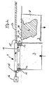
- the coater 9 is additionally with shearer blades 15 provided, in the illustrated embodiment on both sides outside of Coater blades 13 each have a shear blade 15 assigned to them.
- the Coating device 9 by a motor drive 16 and coupled thereto Drive elements such. B. in the form of a spindle 17 to the right over the space 8th move, the shear blades 15 are able to on the construction surface 7, d. H.
- the Surface of the molded part 2 solidified upwards protruding Shear off material projections 18 with their sharpened lower edge 19, so that it is avoided that the coater blades 13 hang on the material projections 18 remain, which leads to a deterioration in the coating result or even to one Damage to the coater 9 could result. It is significant that the downward-facing edges 12 are somewhat rounded, which the Coating result benefits, whereas the edges 19 of the shear blades 15 are hardened and sharpened.
- a coater blade 13 a plurality of Shear blades 15 are associated, the downward shear edges 19 of the Height can be staggered at a small angle.
- the one facing down Edge 12 of the coater blade 13 is arranged slightly lower than that at the bottom pointing shear edge of the shear blade or shear blades.
- the height of the shear blades 15 based on the amount of Coater blade 13 to make it adjustable, for example by a Adjustment element 20 could be carried out by a carrier element Coating device 9 passes through a shear blade holder and as a spindle drive is trained.
- a mechanical damping device 21 is provided between the shearer blades 19 and the blade assembly 10 of the coater blades 13, in order to beat too hard on the shearer blades 15 not on the coater blade or coater blades 13 transferred to.
- the shear blades 15 are on separate brackets 25 mechanically decoupled from the blade assembly 10 of the Coater blades 13 movable.
- Figure 5 the Operation of such a device is shown.
- the Coater device 9 and the two brackets 25a arranged on both sides, 25b of the shearer blades 15 on the left side of a guideway 26 of the holders 25 and the coater 9 Figure 5a.
- the bracket 25b with the there arranged shearer blades 15 from the left position for example the Position over the reservoir 11 may be to the right, d. H. about the installation space process, whereby material projections 18 on the top of the formed Molding 2 are separated.
- the application device 9 is still at rest, likewise the holder 25a (FIG. 5b).
- FIG. 6 There they are Guideways 31 of the coater 9 and the guideway 32 for a Height-adjustable bracket 33 of a shear blade assembly 34 arranged so that bracket 33 of shearer blade assembly 34 both horizontally and vertically can be moved.
- the holder 33 is on a carriage 35 by means of a Height adjustment device 36 arranged, for example, a rack 37 and a May have drive pinion 38.
- a Height adjustment device 36 arranged, for example, a rack 37 and a May have drive pinion 38.
- spindle drives and the like can be used with advantage.
- the height adjustment device makes it possible to the holder 33 with the shear blade assembly 34 along a path 39 over the To lift the coater 9 away so that the shearer blade assembly 34 the coater blades 13 can be used on both sides.
- the Height adjustment device has the additional advantage that it is not only suitable is to lift the holder 33 over the coater 9, but over the height adjustment device also fine adjustment to deepen the actual shearing process can be carried out.
- FIG. 7 shows schematically how two coater blades 13 be arranged at an angle to their path of motion on the coater 9 can.
- other angles of inclination are also possible, it is also conceivable to incline only one of the two coater blades and the other in a conventional manner at right angles to the trajectory to arrange the coater.
Landscapes
- Engineering & Computer Science (AREA)
- Chemical & Material Sciences (AREA)
- Materials Engineering (AREA)
- Mechanical Engineering (AREA)
- Manufacturing & Machinery (AREA)
- Physics & Mathematics (AREA)
- Optics & Photonics (AREA)
- Coating Apparatus (AREA)
- Powder Metallurgy (AREA)
- Application Of Or Painting With Fluid Materials (AREA)
- Producing Shaped Articles From Materials (AREA)
- Medical Preparation Storing Or Oral Administration Devices (AREA)
Abstract
Description
- Fig. 1
- eine schematische Darstellung der für die Erfindung wesentlichen Komponenten einer Bauvorrichtung nach dem Stand der Technik zur Erstellung von Formteilen aus Baumaterial unter Einbringung von Strahlungsenergie, mit einer Beschichtereinrichtung mit zwei Beschichterklingen
- Fig. 2
- eine vergrößerte Darstellung der Beschichtereinrichtung mit Pulverbehälter und Bauraum
- Fig. 3
- eine Detailansicht der Beschichterklinge mit drei gedämpft gelagerten Abscherklingen
- Fig. 4
- eine Beschichterklingenanordnung mit beidseitig angeordneten, gesondert steuerbaren Abscherklingen
- Fig. 5
- einen schematischen Arbeitsablauf einer Vorrichtung gemäß Figur 4
- Fig. 6
- eine Beschichterklingen- und Abscherklingenanordnung, bei der ein Abscherklingensatz über der Beschichterklingenanordnung verfahrbar angeordnet ist,
- Fig. 7
- eine Abscherklingenanordnung in Schrägstellung.
Claims (25)
- Beschichtereinrichtung (9) für eine Bauvorrichtung (1) zur Erstellung von Formteilen (2) aus Baumaterial (3) unter Einbringung von Strahlungsenergie, insbesondere für eine Lasersinteranlage oder eine Stereolithographieanlage, mitdadurch gekennzeichnet, daßmindestens einer horizontal verfahrbaren Klingenanordnung (10) mit mindestens einer Beschichterklinge (13) zum Transport des Baumaterials (3) aus einem Vorratsbehälter (11) in den Bauraum (8), wobei das Baumaterial (3) durch die nach unten weisende Kante (12) der mindestens einen Beschichterklinge (13) als gleichmäßige Schicht auf einer Baufläche (7) aufbringbar ist,der Klingenanordnung (10) mindestens eine Abscherklinge (15) zugeordnet ist, die vor oder beim Beschichtungsvorgang über die Baufläche (7) verfahrbar ist.
- Beschichtereinrichtung nach Anspruch 1,
dadurch gekennzeichnet, daß
die horizontal verfahrbare Klingenanordnung (10) in an sich bekannter Weise zwei voneinander beabstandete Beschichterklingen (13) aufweist und an der Außenseite des Beschichterklingenpaares (13) mindestens je eine Abscherklinge (15) angeordnet ist. - Beschichtereinrichtung nach Anspruch 1 oder 2,
dadurch gekennzeichnet, daß
jeder Beschichterklinge (13) eine Mehrzahl von Abscherklingen (15) zugeordnet ist. - Beschichtereinrichtung nach Anspruch 3,
dadurch gekennzeichnet, daß
die nach unten weisenden Scherkanten (19) der Mehrzahl der Abscherklingen (15) der Höhe nach gestaffelt sind. - Beschichtereinrichtung nach einem der vorhergehenden Ansprüche,
dadurch gekennzeichnet, daß
die nach unten weisende Kante (12) der Beschichterklinge (13) geringfügig tiefer angeordnet ist als die nach unten weisende Scherkante (19) der Abscherklinge(n) (15). - Beschichtereinrichtung nach einem der vorhergehenden Ansprüche,
dadurch gekennzeichnet, daß
die Höhe der Abscherklinge(n) (15) bezogen auf die Höhe der Beschichterklinge(n) (13) verstellbar ist. - Beschichtereinrichtung nach einem der vorhergehenden Ansprüche,
dadurch gekennzeichnet, daß
die mindestens eine Abscherklinge (15) unter Zwischenschaltung einer mechanischen Dämpfungseinrichtung (21) an der horizontal verfahrbaren Klingenanordnung (10) befestigt ist. - Beschichtereinrichtung nach einem der vorhergehenden Ansprüche,
dadurch gekennzeichnet, daß
die mindestens eine Abscherklinge (15) an einer gesonderten Halterung (25) mechanisch entkoppelt von der Klingenanordnung (10) der Beschichterklinge (13) verfahrbar ist. - Beschichtereinrichtung nach einem der vorhergehenden Ansprüche,
dadurch gekennzeichnet, daß
der Klingenanordnung (10) mit zwei Beschichterklingen (13) nur eine Abscherklinge (15) zugeordnet ist, die beidseitig außerhalb der Beschichterklingen (13) der Klingenanordnung (10) zur Voreilung in Transportrichtung des Baumaterials (3) positionierbar ist. - Beschichtereinrichtung nach einem der vorhergehenden Ansprüche,
dadurch gekennzeichnet, daß
das Material der mindestens einen Abscherklinge (15) eine höhere Shore-Härte aufweist als das der Beschichterklinge (13). - Beschichtereinrichtung nach einem der vorhergehenden Ansprüche,
dadurch gekennzeichnet, daß
die nach unten weisende Scherkante (19) der Abscherklinge (15) geschärft ist. - Beschichtereinrichtung nach einem der vorhergehenden Ansprüche,
dadurch gekennzeichnet, daß
die Abscherklinge (15) über die zu beschichtende Baufläche (7) verfahrbar ist, bevor die Transportbewegung der Klingenanordnung (10) mit der mindestens einen Beschichterklinge (13) einleitbar ist. - Beschichtereinrichtung nach einem der vorhergehenden Ansprüche,
dadurch gekennzeichnet, daß
die Abscherklinge(n) (15) austauschbar angeordnet ist (sind). - Beschichtereinrichtung nach einem der vorhergehenden Ansprüche,
dadurch gekennzeichnet, daß
der Antrieb der Abscherklinge(n) (15) gesondert steuerbar ist. - Beschichtereinrichtung nach einem der vorhergehenden Ansprüche,
dadurch gekennzeichnet, daß
die Abscherklinge (15) oder Abscherklingenanordnung (34) an einem motorisch höhenverstellbaren Abscherklingenhalter (33) befestigt ist, der an einem gesonderten, horizontal verfahrbaren Schlitten (35) gelagert ist. - Beschichtereinrichtung nach Anspruch 15,
dadurch gekennzeichnet, daß
die Abscherklingenanordnung (34) über der Klingenanordnung (10) der Beschichterklingen (13) horizontal verfahrbar und neben der Klingenanordnung (10) der Beschichterklingen (13) in Arbeitsposition absenkbar ist. - Beschichtereinrichtung nach einem der vorhergehenden Ansprüche,
dadurch gekennzeichnet, daß
die wirksame Scherkante (19) der Abscherklinge (15) bezogen auf die Bewegungsbahn der Abscherklinge (15) schräg angeordnet ist. - Beschichtereinrichtung (9) für eine Bauvorrichtung (1) zur Erstellung von Formteilen (2) aus Baumaterial (3) unter Einbringung von Strahlungsenergie, insbesondere für eine Lasersinteranlage oder eine Stereolithographieanlage, mitdadurch gekennzeichnet, daßmindestens einer horizontal verfahrbaren Klingenanordnung (10) mit mindestens einer Beschichterklinge (13) zum Transport des Baumaterials (3) aus einem Vorratsbehälter (11) in den Bauraum (8), wobei das Baumaterial (3) durch die nach unten weisende Kante (12) der mindestens einen Beschichterklinge (13) als gleichmäßige Schicht auf einer Baufläche (7) aufbringbar ist,
die mindestens eine Beschichterklinge (13) als Abscherklinge dient, wobei vor dem Abschervorgang der Abstand zwischen einer wirksamen Scherkante (19) der Beschichterklinge (13) und der zu beschichtenden Oberfläche vergrößerbar ist. - Beschichtereinrichtung nach Anspruch 18,
dadurch gekennzeichnet, daß
die zu beschichtende Oberfläche vor dem Abschervorgang in eine abgesenkte Abscherstellung verfahrbar ist. - Beschichtereinrichtung nach Anspruch 18 oder 19,
dadurch gekennzeichnet, daß
die Beschichterklinge (13) vor dem Abschervorgang in eine angehobene Abscherstellung verfahrbar ist. - Beschichtereinrichtung nach einem der vorhergehenden Ansprüche,
dadurch gekennzeichnet, daß
die nach unten weisende Scherkante (19) der Beschichterklinge (13) geschärft ist. - Beschichtereinrichtung nach einem der Ansprüche 18 - 21,
dadurch gekennzeichnet, daß
die Beschichterklingen (13) motorisch verschwenkbar hinsichtlich ihres Anstellwinkels zur Bewegungsbahn der Beschichtereinrichtung (9) ausgebildet sind und beim Beschichtungsvorgang ein erster Anstellwinkel und beim Abschervorgang ein zweiter, modifizierter Anstellwinkel einstellbar ist. - Beschichtereinrichtung nach einem der vorhergehenden Ansprüche,
dadurch gekennzeichnet, daß
der als Scherkante (19) dienende Bereich der Beschichterklinge (13) gehärtet ist. - Beschichtereinrichtung nach einem der vorhergehenden Ansprüche,
dadurch gekennzeichnet, daß
der als Scherkante (19) dienende Bereich der Beschichterklinge (13) mit einer harten Beschichtung versehen ist. - Beschichtereinrichtung nach einem der vorhergehenden Ansprüche,
dadurch gekennzeichnet, daß
die als Abscherklinge (15) dienende Beschichterklinge (13) bezogen auf ihre Bewegungsbahn schräg angeordnet ist.
Applications Claiming Priority (2)
| Application Number | Priority Date | Filing Date | Title |
|---|---|---|---|
| DE10300959A DE10300959C5 (de) | 2003-01-14 | 2003-01-14 | Beschichtereinrichtung für eine Bauvorrichtung zur Erstellung von Formteilen aus Baumaterial |
| DE10300959 | 2003-01-14 |
Publications (2)
| Publication Number | Publication Date |
|---|---|
| EP1439050A1 true EP1439050A1 (de) | 2004-07-21 |
| EP1439050B1 EP1439050B1 (de) | 2006-08-02 |
Family
ID=32519891
Family Applications (1)
| Application Number | Title | Priority Date | Filing Date |
|---|---|---|---|
| EP03029510A Expired - Lifetime EP1439050B1 (de) | 2003-01-14 | 2003-12-20 | Beschichtereinrichtung für eine Bauvorrichtung zur Herstellung von Formteilen aus Pulvermaterial |
Country Status (3)
| Country | Link |
|---|---|
| EP (1) | EP1439050B1 (de) |
| AT (1) | ATE334803T1 (de) |
| DE (2) | DE10300959C5 (de) |
Cited By (18)
| Publication number | Priority date | Publication date | Assignee | Title |
|---|---|---|---|---|
| EP1657048A1 (de) * | 2004-11-11 | 2006-05-17 | Korea Institute Of Machinery & Materials | Prototypensystem für das dreidimensionale Drucken |
| DE102006041320A1 (de) * | 2006-09-01 | 2008-03-13 | Cl Schutzrechtsverwaltungs Gmbh | Beschichtereinrichtung für eine Bauvorrichtung zur Erstellung von Formteilen aus pulverartigem Baumaterial unter Einbringung von Strahlungsenergie |
| WO2008064620A1 (de) * | 2006-11-28 | 2008-06-05 | Cl Schutzrechtsverwaltungs Gmbh | Beschichter- oder ausgleichseinrichtung für eine bauvorrichtung zur erstellung von formteilen aus baumaterial |
| EP2191922A1 (de) | 2008-11-27 | 2010-06-02 | MTT Technologies GmbH | Pulverauftragsvorrichtung für eine Anlage zur Herstellung von Werkstücken durch Beaufschlagen von Pulverschichten mit elektromagnetischer Strahlung oder Teilchenstrahlung |
| EP2286982A1 (de) * | 2009-08-20 | 2011-02-23 | Matthias Fockele | Vorrichtung zur Herstellung von Formkörpern durch schichtweises Aufbauen aus Werkstoffpulver |
| EP2301743A3 (de) * | 2008-05-09 | 2011-11-02 | FIT Fruth Innovative Technologien GmbH | Verfahren und Vorrichtung zum Herstellen eines Formkörpers durch schichtweisen Aufbau |
| EP1769903A3 (de) * | 2005-09-30 | 2013-05-01 | 3D Systems, Inc. | Herstellungssystem und Verfahren zum schnellen Herstellen von Prototypen |
| US20130177767A1 (en) * | 2012-01-06 | 2013-07-11 | Maik Grebe | Apparatus for layer-by-layer production of three-dimensional objects |
| WO2014044676A1 (en) * | 2012-09-18 | 2014-03-27 | Blueprinter Aps | Power feed mechanism for a three-dimensional printer |
| ITVR20120230A1 (it) * | 2012-11-20 | 2014-05-21 | Sisma Spa | Macchina per produrre oggetti tridimensionali a partire da materiali in polvere |
| WO2014191200A1 (de) * | 2013-05-28 | 2014-12-04 | Siemens Aktiengesellschaft | Anordnung zum aufrakeln eines pulvers |
| WO2017143145A1 (en) * | 2016-02-17 | 2017-08-24 | UCT Additive Manufacturing Center Pte. Ltd. | Multi-blade recoater |
| WO2018054727A1 (de) * | 2016-09-22 | 2018-03-29 | Siemens Aktiengesellschaft | Verfahren zum erzeugen eines werkstücks durch ein additives herstellungsverfahren und vorrichtung, die zur durchführung des verfahrens geeignet ist |
| EP3461574A1 (de) * | 2017-10-02 | 2019-04-03 | General Electric Company | Modifizierter rahmen und wiederbeschichtungssystem |
| DE102017010474A1 (de) | 2017-11-10 | 2019-05-16 | O.R. Lasertechnologie Gmbh | Vorrichtung zur Herstellung und Oberflächenbearbeitung eines dreidimensionalen Objekts |
| CN110382208A (zh) * | 2017-01-06 | 2019-10-25 | 通用电气公司 | 用于增材制造重涂覆的系统和方法 |
| US11154934B2 (en) | 2018-01-26 | 2021-10-26 | Concept Laser Gmbh | Build material application device |
| US12134131B2 (en) | 2021-06-16 | 2024-11-05 | General Electric Company | Methods and apparatus for recoating parameter control |
Families Citing this family (16)
| Publication number | Priority date | Publication date | Assignee | Title |
|---|---|---|---|---|
| CN100377816C (zh) * | 2003-02-25 | 2008-04-02 | 松下电工株式会社 | 三维形状造型物的制造方法及制造装置 |
| DE10360094C9 (de) * | 2003-12-20 | 2009-11-05 | Cl Schutzrechtsverwaltungs Gmbh | Pulverdosierung - automatische Pulverzustellung |
| DE102006023484A1 (de) | 2006-05-18 | 2007-11-22 | Eos Gmbh Electro Optical Systems | Vorrichtung und Verfahren zum schichtweisen Herstellen eines dreidimensionalen Objekts aus einem pulverförmigen Aufbaumaterial |
| DE102006055078A1 (de) * | 2006-11-22 | 2008-06-05 | Eos Gmbh Electro Optical Systems | Vorrichtung zum schichtweisen Herstellen eines dreidimensionalen Objekts |
| DE102009035258B4 (de) | 2009-07-29 | 2025-08-21 | Concept Laser Gmbh | Verfahren zum Herstellen eines dreidimensionalen Objektes |
| DE102013223587A1 (de) * | 2013-11-19 | 2015-06-03 | MTU Aero Engines AG | Nivellier- und Glättungsschieber zur Generativen Herstellung von Bauteilen |
| DE102014010929A1 (de) * | 2014-07-28 | 2016-01-28 | Cl Schutzrechtsverwaltungs Gmbh | Vorrichtung zur Herstellung dreidimensionaler Objekte |
| DE102015000100A1 (de) | 2015-01-14 | 2016-07-14 | Cl Schutzrechtsverwaltungs Gmbh | Verfahren zur Hestellung von dreidimensionalen Bauteilen |
| DE102016121594A1 (de) * | 2016-11-10 | 2018-05-17 | Fraunhofer-Gesellschaft zur Förderung der angewandten Forschung e.V. | Verfahren zur verbesserung der oberflächenqualität generativ hergestellter bauteile |
| DE202017005861U1 (de) | 2017-11-10 | 2018-02-21 | O.R. Lasertechnologie Gmbh | Vorrichtung mit einer Fräsvorrichtung zur Herstellung und Oberflächenbearbeitung eines dreidimensionalen Objekts |
| DE202017005855U1 (de) | 2017-11-10 | 2018-02-28 | O.R. Lasertechnologie Gmbh | Vorrichtung mit einer ersten und einer zweiten Trägervorrichtung zur Herstellung und Oberflächenbearbeitung eines dreidimensionalen Objekts |
| DE202017005866U1 (de) | 2017-11-10 | 2018-02-21 | O.R. Lasertechnologie Gmbh | Vorrichtung zur Herstellung und Oberflächenbearbeitung eines dreidimensionalen Objekts |
| FR3081755B1 (fr) * | 2018-05-30 | 2021-09-10 | Safran Aircraft Engines | Racleur, applicable au transport de poudres |
| WO2020075122A1 (en) * | 2018-10-12 | 2020-04-16 | Intech Dmls Pvt Ltd | An apparatus for powder deposition mechanism in an additive manufacturing process |
| CN114126842A (zh) | 2019-05-28 | 2022-03-01 | 伏尔肯模型公司 | 用于增材制造的重涂器系统 |
| EP3976297A4 (de) * | 2019-05-28 | 2023-02-15 | Vulcanforms Inc. | Neubeschichtungssystem für die generative fertigung |
Citations (6)
| Publication number | Priority date | Publication date | Assignee | Title |
|---|---|---|---|---|
| US5730925A (en) * | 1995-04-21 | 1998-03-24 | Eos Gmbh Electro Optical Systems | Method and apparatus for producing a three-dimensional object |
| DE19853978C1 (de) * | 1998-11-23 | 2000-05-25 | Fraunhofer Ges Forschung | Vorrichtung für das selektive Laser-Schmelzen zur Herstellung eines Formkörpers |
| US6136257A (en) * | 1998-03-27 | 2000-10-24 | Eos Gmbh Electro Optical Systems | Apparatus and method for producing a three-dimensional object and for applying a layer of a powder material to a surface |
| DE19928245A1 (de) * | 1999-06-21 | 2001-01-04 | Eos Electro Optical Syst | Einrichtung zum Zuführen von Pulver für eine Lasersintereinrichtung |
| US20020090410A1 (en) * | 2001-01-11 | 2002-07-11 | Shigeaki Tochimoto | Powder material removing apparatus and three dimensional modeling system |
| US20020152002A1 (en) * | 2001-02-21 | 2002-10-17 | Markus Lindemann | Process and device for producing a shaped body by selective laser melting |
-
2003
- 2003-01-14 DE DE10300959A patent/DE10300959C5/de not_active Expired - Fee Related
- 2003-12-20 EP EP03029510A patent/EP1439050B1/de not_active Expired - Lifetime
- 2003-12-20 AT AT03029510T patent/ATE334803T1/de not_active IP Right Cessation
- 2003-12-20 DE DE50304453T patent/DE50304453D1/de not_active Expired - Lifetime
Patent Citations (6)
| Publication number | Priority date | Publication date | Assignee | Title |
|---|---|---|---|---|
| US5730925A (en) * | 1995-04-21 | 1998-03-24 | Eos Gmbh Electro Optical Systems | Method and apparatus for producing a three-dimensional object |
| US6136257A (en) * | 1998-03-27 | 2000-10-24 | Eos Gmbh Electro Optical Systems | Apparatus and method for producing a three-dimensional object and for applying a layer of a powder material to a surface |
| DE19853978C1 (de) * | 1998-11-23 | 2000-05-25 | Fraunhofer Ges Forschung | Vorrichtung für das selektive Laser-Schmelzen zur Herstellung eines Formkörpers |
| DE19928245A1 (de) * | 1999-06-21 | 2001-01-04 | Eos Electro Optical Syst | Einrichtung zum Zuführen von Pulver für eine Lasersintereinrichtung |
| US20020090410A1 (en) * | 2001-01-11 | 2002-07-11 | Shigeaki Tochimoto | Powder material removing apparatus and three dimensional modeling system |
| US20020152002A1 (en) * | 2001-02-21 | 2002-10-17 | Markus Lindemann | Process and device for producing a shaped body by selective laser melting |
Cited By (32)
| Publication number | Priority date | Publication date | Assignee | Title |
|---|---|---|---|---|
| EP1657048A1 (de) * | 2004-11-11 | 2006-05-17 | Korea Institute Of Machinery & Materials | Prototypensystem für das dreidimensionale Drucken |
| EP1769903A3 (de) * | 2005-09-30 | 2013-05-01 | 3D Systems, Inc. | Herstellungssystem und Verfahren zum schnellen Herstellen von Prototypen |
| DE102006041320A1 (de) * | 2006-09-01 | 2008-03-13 | Cl Schutzrechtsverwaltungs Gmbh | Beschichtereinrichtung für eine Bauvorrichtung zur Erstellung von Formteilen aus pulverartigem Baumaterial unter Einbringung von Strahlungsenergie |
| DE102006041320B4 (de) * | 2006-09-01 | 2013-11-28 | Cl Schutzrechtsverwaltungs Gmbh | Beschichtereinrichtung für eine Bauvorrichtung zur Erstellung von Formteilen aus pulverartigem Baumaterial unter Einbringung von Strahlungsenergie |
| WO2008064620A1 (de) * | 2006-11-28 | 2008-06-05 | Cl Schutzrechtsverwaltungs Gmbh | Beschichter- oder ausgleichseinrichtung für eine bauvorrichtung zur erstellung von formteilen aus baumaterial |
| US8652278B2 (en) | 2008-05-09 | 2014-02-18 | Fit Fruth Innovative Technologien Gmbh | Method for producing a shaped body using fibers |
| EP2301743A3 (de) * | 2008-05-09 | 2011-11-02 | FIT Fruth Innovative Technologien GmbH | Verfahren und Vorrichtung zum Herstellen eines Formkörpers durch schichtweisen Aufbau |
| US8409483B2 (en) | 2008-05-09 | 2013-04-02 | Fit Fruth Innovative Technologien Gmbh | Methods and apparatus for use in solid freeform fabrication |
| EP2202016A1 (de) * | 2008-11-27 | 2010-06-30 | MTT Technologies GmbH | Pulverauftragvorrichtung für eine Anlage zur Herstellung von Werkstücken durch Beaufschlagen von Pulverschichten mit elektromagnetischer Strahlung oder Teilchenstrahlung |
| EP2191922A1 (de) | 2008-11-27 | 2010-06-02 | MTT Technologies GmbH | Pulverauftragsvorrichtung für eine Anlage zur Herstellung von Werkstücken durch Beaufschlagen von Pulverschichten mit elektromagnetischer Strahlung oder Teilchenstrahlung |
| EP2286982A1 (de) * | 2009-08-20 | 2011-02-23 | Matthias Fockele | Vorrichtung zur Herstellung von Formkörpern durch schichtweises Aufbauen aus Werkstoffpulver |
| EP2674283A3 (de) * | 2009-08-20 | 2014-05-07 | Matthias Fockele | Vorrichtung zur Herstellung von Formkörpern durch schichtweises Aufbauen aus Werkstoffpulver |
| US20130177767A1 (en) * | 2012-01-06 | 2013-07-11 | Maik Grebe | Apparatus for layer-by-layer production of three-dimensional objects |
| US9738035B2 (en) | 2012-09-18 | 2017-08-22 | Hewlett-Packard Development Company, L.P. | Power feed mechanism for a three-dimensional printer |
| WO2014044676A1 (en) * | 2012-09-18 | 2014-03-27 | Blueprinter Aps | Power feed mechanism for a three-dimensional printer |
| CN104837607A (zh) * | 2012-09-18 | 2015-08-12 | 布鲁普林特公司 | 用于三维打印机的粉末进料机构 |
| CN104837607B (zh) * | 2012-09-18 | 2017-03-22 | 惠普发展公司有限责任合伙企业 | 用于三维打印机的粉末进料机构 |
| ITVR20120230A1 (it) * | 2012-11-20 | 2014-05-21 | Sisma Spa | Macchina per produrre oggetti tridimensionali a partire da materiali in polvere |
| EP2732889A3 (de) * | 2012-11-20 | 2014-11-26 | Sisma S.p.A. | Maschine zur Herstellung dreidimensionaler Objekte aus pulverförmigen Materialien |
| WO2014191200A1 (de) * | 2013-05-28 | 2014-12-04 | Siemens Aktiengesellschaft | Anordnung zum aufrakeln eines pulvers |
| US10105758B2 (en) | 2013-05-28 | 2018-10-23 | Siemens Aktiengesellschaft | Arrangement for coating a powder |
| WO2017143145A1 (en) * | 2016-02-17 | 2017-08-24 | UCT Additive Manufacturing Center Pte. Ltd. | Multi-blade recoater |
| WO2018054727A1 (de) * | 2016-09-22 | 2018-03-29 | Siemens Aktiengesellschaft | Verfahren zum erzeugen eines werkstücks durch ein additives herstellungsverfahren und vorrichtung, die zur durchführung des verfahrens geeignet ist |
| CN110382208A (zh) * | 2017-01-06 | 2019-10-25 | 通用电气公司 | 用于增材制造重涂覆的系统和方法 |
| EP3565708A4 (de) * | 2017-01-06 | 2020-08-05 | General Electric Company | Systeme und verfahren für neubeschichtung in der generativen fertigung |
| EP3461574A1 (de) * | 2017-10-02 | 2019-04-03 | General Electric Company | Modifizierter rahmen und wiederbeschichtungssystem |
| US20190099807A1 (en) * | 2017-10-02 | 2019-04-04 | General Electric Company | Modified frame and recoating system |
| US11273495B2 (en) * | 2017-10-02 | 2022-03-15 | General Electric Company | Modified frame and recoating system |
| DE102017010474A1 (de) | 2017-11-10 | 2019-05-16 | O.R. Lasertechnologie Gmbh | Vorrichtung zur Herstellung und Oberflächenbearbeitung eines dreidimensionalen Objekts |
| US11154934B2 (en) | 2018-01-26 | 2021-10-26 | Concept Laser Gmbh | Build material application device |
| EP3517298B1 (de) * | 2018-01-26 | 2022-12-07 | CL Schutzrechtsverwaltungs GmbH | Baumaterialaufbringungsvorrichtung |
| US12134131B2 (en) | 2021-06-16 | 2024-11-05 | General Electric Company | Methods and apparatus for recoating parameter control |
Also Published As
| Publication number | Publication date |
|---|---|
| EP1439050B1 (de) | 2006-08-02 |
| DE10300959A1 (de) | 2004-07-22 |
| DE10300959C5 (de) | 2013-10-02 |
| ATE334803T1 (de) | 2006-08-15 |
| DE50304453D1 (de) | 2006-09-14 |
| DE10300959B4 (de) | 2007-03-01 |
Similar Documents
| Publication | Publication Date | Title |
|---|---|---|
| EP1439050B1 (de) | Beschichtereinrichtung für eine Bauvorrichtung zur Herstellung von Formteilen aus Pulvermaterial | |
| EP3392019B1 (de) | Vorrichtung zum herstellen von dreidimensionalen objekten durch aufeinander-folgendes verfestigen von schichten sowie ein zugehöriges verfahren | |
| DE202006016477U1 (de) | Vorrichtung zum Herstellen eines dreidimensionalen Objektes | |
| EP2286982B1 (de) | Vorrichtung zur Herstellung von Formkörpern durch schichtweises Aufbauen aus Werkstoffpulver | |
| DE102006041320B4 (de) | Beschichtereinrichtung für eine Bauvorrichtung zur Erstellung von Formteilen aus pulverartigem Baumaterial unter Einbringung von Strahlungsenergie | |
| EP4200101B1 (de) | Verfahren zur herstellung mindestens eines werkstückteils und eines restwerkstücks aus einem werkstück | |
| DE4400523A1 (de) | Verfahren und Vorrichtung zum Herstellen eines dreidimensionalen Objekts | |
| EP3600726A1 (de) | Vorrichtung und verfahren zum herstellen von dreidimensionalen werkstücken | |
| DE3533341A1 (de) | Stuetzvorrichtung zur aufnahme einer mittels eines fluidstrahles aus einem rohling auszuschneidenden scheibe | |
| EP0738584A1 (de) | Vorrichtung und Verfahren zum Herstellen eines dreidimensionalen Objektes | |
| WO2012062253A2 (de) | Vorrichtung zum herstellen, reparieren und/oder austauschen eines bauteils mittels eines durch energiestrahlung verfestigbaren pulvers, sowie ein verfahren und ein gemäss dem verfahren hergestellten bauteils | |
| EP3642038B1 (de) | Vorrichtung und verfahren zum generativen herstellen eines dreidimensionalen objekts mit einem hubsystem | |
| DE60010745T2 (de) | Verfahren und vorrichtung zum brennschneiden eines aus stahl hergestellen werkstückes | |
| DE102011106380B4 (de) | Vorrichtung zur Herstellung von dreidimensionalen Objekten | |
| DE102015121437A1 (de) | Vorrichtung und Verfahren zur Herstellung eines dreidimensionalen metallischen Formkörpers | |
| WO2016150559A1 (de) | Einrichtung und verfahren zum 3d-drucken von werkstücken | |
| EP0585576B1 (de) | Lochstanze | |
| DE102014005916A1 (de) | Vorrichtung zum Herstellen von dreidimensionalen Objekten | |
| DE202012103653U1 (de) | Schieberlippe, insbesondere zum Einsatz in Strahlschmelzanlagen | |
| EP0478530B1 (de) | Schneidanlage zum Abschneiden von Stücken wählbarer Länge von einem Gitterrost | |
| DE102007056572A1 (de) | Verfahren zur Durchführung von Crash-Schlitten-Versuchen, sowie Vorrichtung zum Durchführen des Verfahrens | |
| DE102018128242A1 (de) | Pulverauftragsvorrichtung, Verfahren zum Betreiben einer Pulverauftragsvorrichtung und Anlage zur Herstellung eines dreidimensionalen Werkstücks | |
| DE102005045462B3 (de) | Verfahren und Vorrichtung zum Auslegen einer Gravur | |
| DE202017102341U1 (de) | Laserstrahlschneidvorrichtung | |
| DE102022125140A1 (de) | Verfahren zur Ausbildung eines Nanojoints, zugehöriges Computerprogrammprodukt und Werkstück mit Nanojoint |
Legal Events
| Date | Code | Title | Description |
|---|---|---|---|
| PUAI | Public reference made under article 153(3) epc to a published international application that has entered the european phase |
Free format text: ORIGINAL CODE: 0009012 |
|
| AK | Designated contracting states |
Kind code of ref document: A1 Designated state(s): AT BE BG CH CY CZ DE DK EE ES FI FR GB GR HU IE IT LI LU MC NL PT RO SE SI SK TR |
|
| AX | Request for extension of the european patent |
Extension state: AL LT LV MK |
|
| 17P | Request for examination filed |
Effective date: 20050117 |
|
| AKX | Designation fees paid |
Designated state(s): AT BE BG CH CY CZ DE DK EE ES FI FR GB GR HU IE IT LI LU MC NL PT RO SE SI SK TR |
|
| GRAP | Despatch of communication of intention to grant a patent |
Free format text: ORIGINAL CODE: EPIDOSNIGR1 |
|
| RAP1 | Party data changed (applicant data changed or rights of an application transferred) |
Owner name: CL SCHUTZRECHTSVERWALTUNGS GMBH |
|
| GRAS | Grant fee paid |
Free format text: ORIGINAL CODE: EPIDOSNIGR3 |
|
| GRAA | (expected) grant |
Free format text: ORIGINAL CODE: 0009210 |
|
| AK | Designated contracting states |
Kind code of ref document: B1 Designated state(s): AT BE BG CH CY CZ DE DK EE ES FI FR GB GR HU IE IT LI LU MC NL PT RO SE SI SK TR |
|
| PG25 | Lapsed in a contracting state [announced via postgrant information from national office to epo] |
Ref country code: RO Free format text: LAPSE BECAUSE OF FAILURE TO SUBMIT A TRANSLATION OF THE DESCRIPTION OR TO PAY THE FEE WITHIN THE PRESCRIBED TIME-LIMIT Effective date: 20060802 Ref country code: SI Free format text: LAPSE BECAUSE OF FAILURE TO SUBMIT A TRANSLATION OF THE DESCRIPTION OR TO PAY THE FEE WITHIN THE PRESCRIBED TIME-LIMIT Effective date: 20060802 Ref country code: FI Free format text: LAPSE BECAUSE OF FAILURE TO SUBMIT A TRANSLATION OF THE DESCRIPTION OR TO PAY THE FEE WITHIN THE PRESCRIBED TIME-LIMIT Effective date: 20060802 Ref country code: NL Free format text: LAPSE BECAUSE OF FAILURE TO SUBMIT A TRANSLATION OF THE DESCRIPTION OR TO PAY THE FEE WITHIN THE PRESCRIBED TIME-LIMIT Effective date: 20060802 Ref country code: IE Free format text: LAPSE BECAUSE OF FAILURE TO SUBMIT A TRANSLATION OF THE DESCRIPTION OR TO PAY THE FEE WITHIN THE PRESCRIBED TIME-LIMIT Effective date: 20060802 Ref country code: SK Free format text: LAPSE BECAUSE OF FAILURE TO SUBMIT A TRANSLATION OF THE DESCRIPTION OR TO PAY THE FEE WITHIN THE PRESCRIBED TIME-LIMIT Effective date: 20060802 Ref country code: CZ Free format text: LAPSE BECAUSE OF FAILURE TO SUBMIT A TRANSLATION OF THE DESCRIPTION OR TO PAY THE FEE WITHIN THE PRESCRIBED TIME-LIMIT Effective date: 20060802 |
|
| REG | Reference to a national code |
Ref country code: GB Ref legal event code: FG4D Free format text: NOT ENGLISH |
|
| REG | Reference to a national code |
Ref country code: CH Ref legal event code: EP |
|
| REG | Reference to a national code |
Ref country code: IE Ref legal event code: FG4D Free format text: LANGUAGE OF EP DOCUMENT: GERMAN |
|
| REF | Corresponds to: |
Ref document number: 50304453 Country of ref document: DE Date of ref document: 20060914 Kind code of ref document: P |
|
| PG25 | Lapsed in a contracting state [announced via postgrant information from national office to epo] |
Ref country code: SE Free format text: LAPSE BECAUSE OF FAILURE TO SUBMIT A TRANSLATION OF THE DESCRIPTION OR TO PAY THE FEE WITHIN THE PRESCRIBED TIME-LIMIT Effective date: 20061102 Ref country code: DK Free format text: LAPSE BECAUSE OF FAILURE TO SUBMIT A TRANSLATION OF THE DESCRIPTION OR TO PAY THE FEE WITHIN THE PRESCRIBED TIME-LIMIT Effective date: 20061102 Ref country code: BG Free format text: LAPSE BECAUSE OF FAILURE TO SUBMIT A TRANSLATION OF THE DESCRIPTION OR TO PAY THE FEE WITHIN THE PRESCRIBED TIME-LIMIT Effective date: 20061102 |
|
| GBT | Gb: translation of ep patent filed (gb section 77(6)(a)/1977) |
Effective date: 20061016 |
|
| PG25 | Lapsed in a contracting state [announced via postgrant information from national office to epo] |
Ref country code: ES Free format text: LAPSE BECAUSE OF FAILURE TO SUBMIT A TRANSLATION OF THE DESCRIPTION OR TO PAY THE FEE WITHIN THE PRESCRIBED TIME-LIMIT Effective date: 20061113 |
|
| PG25 | Lapsed in a contracting state [announced via postgrant information from national office to epo] |
Ref country code: BE Free format text: LAPSE BECAUSE OF NON-PAYMENT OF DUE FEES Effective date: 20061231 Ref country code: MC Free format text: LAPSE BECAUSE OF NON-PAYMENT OF DUE FEES Effective date: 20061231 |
|
| NLV1 | Nl: lapsed or annulled due to failure to fulfill the requirements of art. 29p and 29m of the patents act | ||
| PG25 | Lapsed in a contracting state [announced via postgrant information from national office to epo] |
Ref country code: PT Free format text: LAPSE BECAUSE OF FAILURE TO SUBMIT A TRANSLATION OF THE DESCRIPTION OR TO PAY THE FEE WITHIN THE PRESCRIBED TIME-LIMIT Effective date: 20070102 |
|
| ET | Fr: translation filed | ||
| REG | Reference to a national code |
Ref country code: IE Ref legal event code: FD4D |
|
| PLBI | Opposition filed |
Free format text: ORIGINAL CODE: 0009260 |
|
| PLAX | Notice of opposition and request to file observation + time limit sent |
Free format text: ORIGINAL CODE: EPIDOSNOBS2 |
|
| 26 | Opposition filed |
Opponent name: EOS GMBH ELECTRO OPTICAL SYSTEMS Effective date: 20070502 |
|
| PLBB | Reply of patent proprietor to notice(s) of opposition received |
Free format text: ORIGINAL CODE: EPIDOSNOBS3 |
|
| BERE | Be: lapsed |
Owner name: CL SCHUTZRECHTSVERWALTUNGS G.M.B.H. Effective date: 20061231 |
|
| PG25 | Lapsed in a contracting state [announced via postgrant information from national office to epo] |
Ref country code: GR Free format text: LAPSE BECAUSE OF FAILURE TO SUBMIT A TRANSLATION OF THE DESCRIPTION OR TO PAY THE FEE WITHIN THE PRESCRIBED TIME-LIMIT Effective date: 20061103 |
|
| PG25 | Lapsed in a contracting state [announced via postgrant information from national office to epo] |
Ref country code: EE Free format text: LAPSE BECAUSE OF FAILURE TO SUBMIT A TRANSLATION OF THE DESCRIPTION OR TO PAY THE FEE WITHIN THE PRESCRIBED TIME-LIMIT Effective date: 20060802 |
|
| PG25 | Lapsed in a contracting state [announced via postgrant information from national office to epo] |
Ref country code: LU Free format text: LAPSE BECAUSE OF NON-PAYMENT OF DUE FEES Effective date: 20061220 Ref country code: HU Free format text: LAPSE BECAUSE OF FAILURE TO SUBMIT A TRANSLATION OF THE DESCRIPTION OR TO PAY THE FEE WITHIN THE PRESCRIBED TIME-LIMIT Effective date: 20070203 Ref country code: TR Free format text: LAPSE BECAUSE OF FAILURE TO SUBMIT A TRANSLATION OF THE DESCRIPTION OR TO PAY THE FEE WITHIN THE PRESCRIBED TIME-LIMIT Effective date: 20060802 |
|
| PG25 | Lapsed in a contracting state [announced via postgrant information from national office to epo] |
Ref country code: CY Free format text: LAPSE BECAUSE OF FAILURE TO SUBMIT A TRANSLATION OF THE DESCRIPTION OR TO PAY THE FEE WITHIN THE PRESCRIBED TIME-LIMIT Effective date: 20060802 |
|
| PGFP | Annual fee paid to national office [announced via postgrant information from national office to epo] |
Ref country code: CH Payment date: 20081222 Year of fee payment: 6 |
|
| PGFP | Annual fee paid to national office [announced via postgrant information from national office to epo] |
Ref country code: AT Payment date: 20081218 Year of fee payment: 6 |
|
| PGFP | Annual fee paid to national office [announced via postgrant information from national office to epo] |
Ref country code: IT Payment date: 20081223 Year of fee payment: 6 |
|
| PGFP | Annual fee paid to national office [announced via postgrant information from national office to epo] |
Ref country code: FR Payment date: 20081216 Year of fee payment: 6 |
|
| PGFP | Annual fee paid to national office [announced via postgrant information from national office to epo] |
Ref country code: GB Payment date: 20081219 Year of fee payment: 6 |
|
| REG | Reference to a national code |
Ref country code: CH Ref legal event code: PL |
|
| GBPC | Gb: european patent ceased through non-payment of renewal fee |
Effective date: 20091220 |
|
| PG25 | Lapsed in a contracting state [announced via postgrant information from national office to epo] |
Ref country code: AT Free format text: LAPSE BECAUSE OF NON-PAYMENT OF DUE FEES Effective date: 20091220 |
|
| REG | Reference to a national code |
Ref country code: FR Ref legal event code: ST Effective date: 20100831 |
|
| PG25 | Lapsed in a contracting state [announced via postgrant information from national office to epo] |
Ref country code: LI Free format text: LAPSE BECAUSE OF NON-PAYMENT OF DUE FEES Effective date: 20091231 Ref country code: CH Free format text: LAPSE BECAUSE OF NON-PAYMENT OF DUE FEES Effective date: 20091231 Ref country code: FR Free format text: LAPSE BECAUSE OF NON-PAYMENT OF DUE FEES Effective date: 20091231 |
|
| PG25 | Lapsed in a contracting state [announced via postgrant information from national office to epo] |
Ref country code: GB Free format text: LAPSE BECAUSE OF NON-PAYMENT OF DUE FEES Effective date: 20091220 |
|
| PG25 | Lapsed in a contracting state [announced via postgrant information from national office to epo] |
Ref country code: IT Free format text: LAPSE BECAUSE OF NON-PAYMENT OF DUE FEES Effective date: 20091220 |
|
| PLBP | Opposition withdrawn |
Free format text: ORIGINAL CODE: 0009264 |
|
| PLBD | Termination of opposition procedure: decision despatched |
Free format text: ORIGINAL CODE: EPIDOSNOPC1 |
|
| PLBM | Termination of opposition procedure: date of legal effect published |
Free format text: ORIGINAL CODE: 0009276 |
|
| STAA | Information on the status of an ep patent application or granted ep patent |
Free format text: STATUS: OPPOSITION PROCEDURE CLOSED |
|
| 27C | Opposition proceedings terminated |
Effective date: 20130916 |
|
| REG | Reference to a national code |
Ref country code: DE Ref legal event code: R079 Ref document number: 50304453 Country of ref document: DE Free format text: PREVIOUS MAIN CLASS: B29C0067000000 Ipc: B29C0064106000 |
|
| PGFP | Annual fee paid to national office [announced via postgrant information from national office to epo] |
Ref country code: DE Payment date: 20221122 Year of fee payment: 20 |
|
| REG | Reference to a national code |
Ref country code: DE Ref legal event code: R081 Ref document number: 50304453 Country of ref document: DE Owner name: CONCEPT LASER GMBH, DE Free format text: FORMER OWNER: CL SCHUTZRECHTSVERWALTUNGS GMBH, 96215 LICHTENFELS, DE |
|
| P01 | Opt-out of the competence of the unified patent court (upc) registered |
Effective date: 20230515 |
|
| P02 | Opt-out of the competence of the unified patent court (upc) changed |
Effective date: 20230530 |
|
| REG | Reference to a national code |
Ref country code: DE Ref legal event code: R071 Ref document number: 50304453 Country of ref document: DE |