EP1440210B1 - Hydraulic milling machine for excavators - Google Patents
Hydraulic milling machine for excavators Download PDFInfo
- Publication number
- EP1440210B1 EP1440210B1 EP02775064A EP02775064A EP1440210B1 EP 1440210 B1 EP1440210 B1 EP 1440210B1 EP 02775064 A EP02775064 A EP 02775064A EP 02775064 A EP02775064 A EP 02775064A EP 1440210 B1 EP1440210 B1 EP 1440210B1
- Authority
- EP
- European Patent Office
- Prior art keywords
- grooved
- shaft
- drum
- milling
- frame structure
- Prior art date
- Legal status (The legal status is an assumption and is not a legal conclusion. Google has not performed a legal analysis and makes no representation as to the accuracy of the status listed.)
- Expired - Lifetime
Links
Images





Classifications
-
- E—FIXED CONSTRUCTIONS
- E02—HYDRAULIC ENGINEERING; FOUNDATIONS; SOIL SHIFTING
- E02F—DREDGING; SOIL-SHIFTING
- E02F3/00—Dredgers; Soil-shifting machines
- E02F3/04—Dredgers; Soil-shifting machines mechanically-driven
- E02F3/18—Dredgers; Soil-shifting machines mechanically-driven with digging wheels turning round an axis, e.g. bucket-type wheels
- E02F3/20—Dredgers; Soil-shifting machines mechanically-driven with digging wheels turning round an axis, e.g. bucket-type wheels with tools that only loosen the material, i.e. mill-type wheels
- E02F3/205—Dredgers; Soil-shifting machines mechanically-driven with digging wheels turning round an axis, e.g. bucket-type wheels with tools that only loosen the material, i.e. mill-type wheels with a pair of digging wheels, e.g. slotting machines
Definitions
- the invention concerns the technology of the mechanisms for the emotion transmission from an hydraulic motor to milling rotating tools, included in the international classification E01 c.
- the patent US 4,883,134 discloses a motor-driven milling machine construction for cutting trenches in the ground, in which there are two rotating semi-drums with cutting tools at their periphery.
- the drums are mounted on a central support.
- the sole function of the motor is to transmit a rotational torque to the semi-drums without transmitting any other forces.
- the stress exerted on the cutting tools is directly transmitted to the central support without going through the motor frame.
- the document DE 195 39 249 A1 is directed to a milling machine.
- a milling machine is provided for forming trenches.
- the machine comprises a pair of coaxially arranged semi-drums, which are supported at an exterior perimeter on a support ring.
- the drums are connected to a shaft which is rotated by motors, the motors being arranged in an interior space between the semi-drums.
- the semi-drums are supported at a central support which is a plate extending substantially in a vertical direction having an opening provided in the central support for passing the shaft therethrough.
- the vertical plate extends throughout the entire height of the semi-drums wherein supporting elements are integrally formed with the plate to both sides.
- the supporting elements project perpendicularly with respect to the vertical plate and are intended for receiving the semi-drums. Between the drums and the supporting elements bearings are respectively inserted.
- the extraordinary resistance of the device object of the present invention is of course obtained by the characteristic separation of two kinds of stresses. Only the torsion stresses for the transmission of the motor torque of the hydraulic motor are absorbed by the grooved shaft inserted in the central rotor while the other stresses are absorbed by the frame structure through the bolted side supports.
Landscapes
- Engineering & Computer Science (AREA)
- Mechanical Engineering (AREA)
- Mining & Mineral Resources (AREA)
- Civil Engineering (AREA)
- General Engineering & Computer Science (AREA)
- Structural Engineering (AREA)
- Earth Drilling (AREA)
- Pit Excavations, Shoring, Fill Or Stabilisation Of Slopes (AREA)
- Shovels (AREA)
Description
- The invention concerns the technology of the mechanisms for the emotion transmission from an hydraulic motor to milling rotating tools, included in the international classification E01 c.
- It is known the employment of hydraulic motor to activate rotating operating tools and in particular milling machines that operate on stony compact materials. The known equipment, besides transmitting the necessary torque to operate the heavy milling operations, must also bear the bending stress and the shocks caused by the rapid impact of the tools against the rocky walls. The bending stress is increased by the fact that the milling drums are assembled overhanging on the motor shaft in order to perform penetrations in the rocky walls.
- The patent
US 4,883,134 discloses a motor-driven milling machine construction for cutting trenches in the ground, in which there are two rotating semi-drums with cutting tools at their periphery. The drums are mounted on a central support. The sole function of the motor is to transmit a rotational torque to the semi-drums without transmitting any other forces. The stress exerted on the cutting tools is directly transmitted to the central support without going through the motor frame. - The document
DE 195 39 249 A1 is directed to a milling machine. A milling machine is provided for forming trenches. The machine comprises a pair of coaxially arranged semi-drums, which are supported at an exterior perimeter on a support ring. The drums are connected to a shaft which is rotated by motors, the motors being arranged in an interior space between the semi-drums. The semi-drums are supported at a central support which is a plate extending substantially in a vertical direction having an opening provided in the central support for passing the shaft therethrough. The vertical plate extends throughout the entire height of the semi-drums wherein supporting elements are integrally formed with the plate to both sides. The supporting elements project perpendicularly with respect to the vertical plate and are intended for receiving the semi-drums. Between the drums and the supporting elements bearings are respectively inserted. - Such operational needs have demonstrated that motor shaft it is often not able to bear for long the combined effect of the heavy stresses during the milling operations. The problem to be solved is to increase the overall resistance and the life of the transmission organs. The present invention suggests an optimal solution for the problems that still affect this field of technology. The finding object of the present invention is also characterized by limited dimensions, economic realization and convenience during maintenance operations.
- The invention is now disclosed with reference to the figures of the attached drawings as a not limiting example.
-
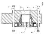
Figure 1 is a view of the extractable transmission shaft that transmits the torque from a central hydraulic motor with two milling side drums. -
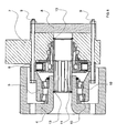
Figure 2 is a view of an extractable transmission shaft that transmits the torque from a central hydraulic motor to a single side milling drum. -
Figures 1 and 2 highlight the simplicity of execution of the transmission shaft that is inserted and extracted with surprising simplicity just because its only function is to transmit the torque of the hydraulic central motor without bearing any other stress that milling drums are likely to encounter during heavy excavation operations. -
Figure3 is a schematic section of the rotor of an hydraulic motor that can be applied to a frame structure of an operator machine. It can be noticed acentral groove 2 where the grooved shaft, that transmits the torque of the hydraulic motor without suffering any milling related stress, is inserted and extracted. -
Figure 4 is an axis section of a support for a milling drum. It can be noticed the central grooves of the drum in which can be inserted and extracted the grooved shaft that transmits to the milling drum only the torque of the hydraulic motor but it does not suffer the other stresses caused by the heavy milling conditions. -
Figure 5 is an axis section of the side supports applied to the frame structure through the connecting bolts. It can be noticed that inside said supports are inserted taper roller bearings upon which are assembled the hubs of the side milling drums.Figure 5 presents a case where in the axial grooves of the side drums and of the hydraulic central motor can be inserted and then extracted the grooved shaft that transmits the torque to the milling drums held by the supports bolted to the frame structure. It can be noticed that the grooved shaft it is not yet assembled or it has already been extracted. -
Figure 6 presents a grooved shaft already inserted in the groove of the side drums and in the main groove of the hydraulic motor. -
Figure 7 represents a version of the invention with a single side drum. It can be noticed that the grooved shaft it has not been inserted yet or it has been already extracted from the central groove. -
Figure 8 represents the same version offigure 7 with the grooved shaft already inserted in the relative grooves. -
Figure 9 schematizes an external view of the application of two side drums. -
Figure 10 schematizes an external view of the application of a single drum. -
Figure 11 is a three-dimensional representation of the application of two side drums. -
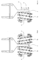
Figure 12 schematizes a side view of the application of the milling machine at the edge of an operator arm of a machine. -
Figure 13 schematizes in perspective a milling head with two side drums. - In the figures each single detail is marked as follows:
- 1 is a grooved shaft that can be inserted and extracted in the groove rotor of an hydraulic motor.
- 2 is the grooved rotor of a central hydraulic motor.
- 3 is the inner groove of the hub of a milling drum.
- 4 is a milling drum.
- 5 is a support that is bolted to a frame central structure.
- 6 is a hydraulic stator bolted to the frame central structure.
- 7 is the frame central structure.
- 8 is closing cover of the version with a single side drum.
- 9 are bolts for the application to the central structure.
- 10 are the bearings for the support of the drums applied to support 5 bolted to the structure frame.
- 11 is a partially grooved shaft for the version with a single side drum.
- 12 indicates the distributor of the hydraulic motor.
- 13 are elastic retaining rings of the extractable grooved shafts.
- 14 are milling tools applied to the drum of a milling machine The evidence of the figures highlights the simplicity of realization and convenience of the maintenance operations for the replacement of the grooved shaft.
- The extraordinary resistance of the device object of the present invention is of course obtained by the characteristic separation of two kinds of stresses. Only the torsion stresses for the transmission of the motor torque of the hydraulic motor are absorbed by the grooved shaft inserted in the central rotor while the other stresses are absorbed by the frame structure through the bolted side supports.
- The invention of course allows for several variations of practical realization as far as the dimensioning and the structural proportioning are concerned and for the technological choices of the material for the realization of the details.
Claims (1)
- Hydraulic milling machine for excavators comprising:a milling drum (4);a support (5), said support including a bearing (10) for supporting said milling drum (4) inside said support (5);a frame structure (7), said frame structure (7) having applied thereon a hydraulic motor (12), which comprises a rotor (2) having a first grooved shaft connection (2) for engagement with a grooved motor shaft (1; 11) for driving said milling drum (4) by said hydraulic motor (12), and said frame structure (7) being adapted to have mounted thereon said support (5) such that only torsional stresses, caused by said milling drum (4) during operation thereof, act on said grooved motor shaft (1; 11);wherein said grooved motor shaft (1; 11) is extractable from said drum (4) while said drum (4) is connected to said frame structure (7);characterized in that
said bearings (10) are taper roller bearings,
said milling drum (4) comprises an integrally formed hub with a second grooved shaft connection (3) for engagement with said grooved motor shaft (1; 11),
a first annular groove is provided in said drum (4) adjacent said second grooved shaft connection (3);
a second annular groove either provided in said frame structure (7), opposite to said first and second grooved shaft connections (2, 3), or provided in a further milling drum (4) adjacent to a second grooved shaft connection (3) thereof;
wherein said first and second annular grooves are provided exteriorly with respect to said grooved motor shaft (1; 11), when said shaft (1; 11) is in an inserted condition for receiving elastic retaining rings (13).
Applications Claiming Priority (3)
| Application Number | Priority Date | Filing Date | Title |
|---|---|---|---|
| IT2001BO000632A ITBO20010632A1 (en) | 2001-10-16 | 2001-10-16 | HYDRAULIC MILLING MACHINE FOR EXCAVATOR MACHINES |
| ITBO20010632 | 2001-10-16 | ||
| PCT/IB2002/004171 WO2003033826A1 (en) | 2001-10-16 | 2002-10-11 | Hydraulic milling machine for excavators |
Publications (2)
| Publication Number | Publication Date |
|---|---|
| EP1440210A1 EP1440210A1 (en) | 2004-07-28 |
| EP1440210B1 true EP1440210B1 (en) | 2010-07-14 |
Family
ID=11439657
Family Applications (1)
| Application Number | Title | Priority Date | Filing Date |
|---|---|---|---|
| EP02775064A Expired - Lifetime EP1440210B1 (en) | 2001-10-16 | 2002-10-11 | Hydraulic milling machine for excavators |
Country Status (6)
| Country | Link |
|---|---|
| US (1) | US20040256908A1 (en) |
| EP (1) | EP1440210B1 (en) |
| DE (1) | DE60237027D1 (en) |
| ES (1) | ES2349193T3 (en) |
| IT (1) | ITBO20010632A1 (en) |
| WO (1) | WO2003033826A1 (en) |
Cited By (1)
| Publication number | Priority date | Publication date | Assignee | Title |
|---|---|---|---|---|
| DE202010010857U1 (en) | 2010-07-30 | 2010-10-21 | MTS Gesellschaft für Maschinentechnik und Sonderbauten mbH | milling device |
Families Citing this family (13)
| Publication number | Priority date | Publication date | Assignee | Title |
|---|---|---|---|---|
| FR2899608B1 (en) * | 2006-04-06 | 2010-04-16 | Cie Du Sol | DRILLING TOOLS |
| FR2904338B1 (en) * | 2006-07-28 | 2011-03-04 | Cie Du Sol | CUTTING HEAD FOR EXCAVATION MACHINE |
| FR2904339B1 (en) * | 2006-07-28 | 2011-03-04 | Cie Du Sol | CUTTING HEAD FOR AN EXCAVATION MACHINE |
| FR2914331B1 (en) | 2007-03-28 | 2009-07-03 | Cie Du Sol Soc Civ Ile | CUTTING HEAD FOR ROTATING STRAW GROUT CUTTING MACHINE |
| DE102008016673B4 (en) | 2008-03-26 | 2014-05-15 | Allu Deutschland Gmbh | Device for milling and mixing of soils |
| DE102008041982B4 (en) † | 2008-09-11 | 2010-06-17 | Klaus Ertmer | Cultivation system with cutting heads and milling chain |
| IT1400429B1 (en) * | 2009-12-15 | 2013-05-31 | Soilmec Spa | TOOL FOR THIN DIAPHRAGMENTS. |
| DE102010013983B4 (en) * | 2010-04-06 | 2016-01-21 | Bomag Gmbh | Milling roller for a ground milling machine and ground milling machine |
| DE102010024428A1 (en) | 2010-06-21 | 2011-12-22 | Ulrich Bechem | Cultivation milling cutter for use as transverse cutting milling cutter, has drum including middle axes that are evenly or unevenly pivotably arranged in same direction in angles larger than specific degree to middle line of base carrier |
| WO2012045327A1 (en) * | 2010-10-08 | 2012-04-12 | Simex Engineering S.R.L. | Cutter heads for ground or walls cutter machines and cutter machines provided with such cutter heads |
| US9200423B2 (en) | 2011-06-06 | 2015-12-01 | Gms Mine Repair And Maintenance, Inc. | Cleaning vehicle, vehicle system and method |
| FR2989098B1 (en) * | 2012-04-05 | 2015-03-20 | Witeck | MILLING DEVICE ADAPTABLE ON A PUBLIC WORKS MACHINE |
| IT202100031592A1 (en) * | 2021-12-16 | 2023-06-16 | Mecc Breganzese S P A In Breve Mb S P A | ROTARY DISGREGERATOR FOR EXCAVATORS AND OPERATING MACHINES IN GENERAL |
Family Cites Families (11)
| Publication number | Priority date | Publication date | Assignee | Title |
|---|---|---|---|---|
| ES420924A1 (en) * | 1972-12-14 | 1976-04-01 | Hydrosol | Device for drilling in hard rock formation |
| AT339235B (en) * | 1975-09-02 | 1977-10-10 | Voest Ag | SCRAPING MACHINE |
| DE3612020A1 (en) * | 1986-04-10 | 1987-10-15 | Hochtief Ag Hoch Tiefbauten | DEVICE FOR INSERTING AN ESSENTIAL VERTICAL FLOOR SLOT |
| AT385086B (en) * | 1986-04-16 | 1988-02-10 | Voest Alpine Ag | DRIVE ARRANGEMENT FOR THE SCRAPER HEADS OF A SCRAPER |
| FR2604460B1 (en) * | 1986-09-26 | 1991-05-10 | Soletanche | DEVICE FOR A MACHINE FOR EXCAVATING TRENCHES IN THE SOIL BY MILLING |
| US5478139A (en) * | 1993-05-25 | 1995-12-26 | Rockmaster Equipment Manufacturing, Inc. | Mobile digging/cutting system |
| IT1267930B1 (en) * | 1994-10-21 | 1997-02-18 | Casagrande Spa | CUTTER WITH SOCKET SUPPORT |
| DE19645650C1 (en) * | 1996-11-06 | 1998-01-22 | Webster Schaeff & Co | Rock face cutting head |
| US5975644A (en) * | 1997-07-28 | 1999-11-02 | Lang; William J. | Grinder mixer assembly |
| AUPP764598A0 (en) * | 1998-12-11 | 1999-01-14 | R N Cribb Pty Limited | Rotary drum cutting head |
| EP1183440B1 (en) * | 1999-06-08 | 2004-08-11 | VOEST-ALPINE Bergtechnik Gesellschaft m.b.H | Stone head to be mounted on excavator arms |
-
2001
- 2001-10-16 IT IT2001BO000632A patent/ITBO20010632A1/en unknown
-
2002
- 2002-10-11 EP EP02775064A patent/EP1440210B1/en not_active Expired - Lifetime
- 2002-10-11 WO PCT/IB2002/004171 patent/WO2003033826A1/en not_active Ceased
- 2002-10-11 US US10/493,012 patent/US20040256908A1/en not_active Abandoned
- 2002-10-11 ES ES02775064T patent/ES2349193T3/en not_active Expired - Lifetime
- 2002-10-11 DE DE60237027T patent/DE60237027D1/en not_active Expired - Lifetime
Cited By (2)
| Publication number | Priority date | Publication date | Assignee | Title |
|---|---|---|---|---|
| DE202010010857U1 (en) | 2010-07-30 | 2010-10-21 | MTS Gesellschaft für Maschinentechnik und Sonderbauten mbH | milling device |
| EP2412873A2 (en) | 2010-07-30 | 2012-02-01 | MTS Gesellschaft für Maschinentechnik und Sonderbauten MBH | Milling device |
Also Published As
| Publication number | Publication date |
|---|---|
| ITBO20010632A1 (en) | 2003-04-16 |
| EP1440210A1 (en) | 2004-07-28 |
| ES2349193T3 (en) | 2010-12-28 |
| WO2003033826A1 (en) | 2003-04-24 |
| DE60237027D1 (en) | 2010-08-26 |
| US20040256908A1 (en) | 2004-12-23 |
Similar Documents
| Publication | Publication Date | Title |
|---|---|---|
| EP1440210A1 (en) | Hydraulic milling machine for excavators | |
| US4883134A (en) | Milling machine for cutting trenches | |
| KR102227205B1 (en) | Fastening device for piping inlet and rotary quick coupler with them | |
| JP5103331B2 (en) | Marine thruster | |
| US7066076B2 (en) | Motor-driven, boom-mounted rotary coupling | |
| US5975644A (en) | Grinder mixer assembly | |
| US6158818A (en) | Rock cutting head | |
| US20220034046A1 (en) | Soil preparation roller system for a soil preparation machine | |
| US8128178B2 (en) | Cutter head for a ground cutter machine having rotary cutters | |
| EP1607360B1 (en) | Elevator hoisting machine | |
| CN112690084A (en) | Lawn trimming hob driven by built-in external rotor motor and lawn maintenance tool | |
| CN212896564U (en) | Shell structure of hydraulic breaking hammer | |
| EP1612013B1 (en) | Rotary cutter and rotary cutting apparatus provided with the rotary cutter | |
| JP2010121644A (en) | Flexible coupling structure and marine thruster device having the same | |
| WO2022129673A1 (en) | Screening, crushing or mixing blade arrangement arranged in the bucket of a working machine | |
| EP1796840B1 (en) | Crushing device | |
| RU2391504C2 (en) | Drive device for rotary tool, which operates with oscillation loading, and tool with such device | |
| US7591514B2 (en) | Cutter head for an excavator machine | |
| US9964154B2 (en) | Drive arrangement for direct drive rotor | |
| US20180280985A1 (en) | Rotor for a disintegration device | |
| RU2100599C1 (en) | Working member of mining machine | |
| JP2007239402A (en) | Shield machine | |
| KR20220023452A (en) | Drive motor module for vehicle | |
| EP3170939B1 (en) | Pivotally flexible mounting interface for a rotatable shaft | |
| ITUD940174A1 (en) | CUTTER WITH BEARING SUPPORT |
Legal Events
| Date | Code | Title | Description |
|---|---|---|---|
| PUAI | Public reference made under article 153(3) epc to a published international application that has entered the european phase |
Free format text: ORIGINAL CODE: 0009012 |
|
| 17P | Request for examination filed |
Effective date: 20040517 |
|
| AK | Designated contracting states |
Kind code of ref document: A1 Designated state(s): AT BE BG CH CY CZ DE DK EE ES FI FR GB GR IE IT LI LU MC NL PT SE SK TR |
|
| AX | Request for extension of the european patent |
Extension state: AL LT LV MK RO SI |
|
| R17C | First examination report despatched (corrected) |
Effective date: 20060109 |
|
| GRAP | Despatch of communication of intention to grant a patent |
Free format text: ORIGINAL CODE: EPIDOSNIGR1 |
|
| GRAS | Grant fee paid |
Free format text: ORIGINAL CODE: EPIDOSNIGR3 |
|
| GRAA | (expected) grant |
Free format text: ORIGINAL CODE: 0009210 |
|
| AK | Designated contracting states |
Kind code of ref document: B1 Designated state(s): DE ES FR GB IT |
|
| REG | Reference to a national code |
Ref country code: GB Ref legal event code: FG4D |
|
| REF | Corresponds to: |
Ref document number: 60237027 Country of ref document: DE Date of ref document: 20100826 Kind code of ref document: P |
|
| REG | Reference to a national code |
Ref country code: ES Ref legal event code: FG2A Effective date: 20101215 |
|
| PLBE | No opposition filed within time limit |
Free format text: ORIGINAL CODE: 0009261 |
|
| STAA | Information on the status of an ep patent application or granted ep patent |
Free format text: STATUS: NO OPPOSITION FILED WITHIN TIME LIMIT |
|
| 26N | No opposition filed |
Effective date: 20110415 |
|
| REG | Reference to a national code |
Ref country code: DE Ref legal event code: R097 Ref document number: 60237027 Country of ref document: DE Effective date: 20110415 |
|
| REG | Reference to a national code |
Ref country code: DE Ref legal event code: R082 Ref document number: 60237027 Country of ref document: DE Representative=s name: STOLMAR & PARTNER, DE Ref country code: DE Ref legal event code: R082 Ref document number: 60237027 Country of ref document: DE Representative=s name: PATENTANWAELTE STOLMAR & PARTNER, DE Ref country code: DE Ref legal event code: R082 Ref document number: 60237027 Country of ref document: DE Representative=s name: STOLMAR & PARTNER PATENTANWAELTE PARTG MBB, DE |
|
| REG | Reference to a national code |
Ref country code: FR Ref legal event code: PLFP Year of fee payment: 14 |
|
| REG | Reference to a national code |
Ref country code: FR Ref legal event code: PLFP Year of fee payment: 15 |
|
| REG | Reference to a national code |
Ref country code: FR Ref legal event code: PLFP Year of fee payment: 16 |
|
| REG | Reference to a national code |
Ref country code: FR Ref legal event code: PLFP Year of fee payment: 17 |
|
| PGFP | Annual fee paid to national office [announced via postgrant information from national office to epo] |
Ref country code: IT Payment date: 20190813 Year of fee payment: 18 |
|
| PGFP | Annual fee paid to national office [announced via postgrant information from national office to epo] |
Ref country code: DE Payment date: 20191031 Year of fee payment: 18 |
|
| PGFP | Annual fee paid to national office [announced via postgrant information from national office to epo] |
Ref country code: ES Payment date: 20191105 Year of fee payment: 18 |
|
| PGFP | Annual fee paid to national office [announced via postgrant information from national office to epo] |
Ref country code: GB Payment date: 20191021 Year of fee payment: 18 |
|
| PGFP | Annual fee paid to national office [announced via postgrant information from national office to epo] |
Ref country code: FR Payment date: 20200114 Year of fee payment: 18 |
|
| REG | Reference to a national code |
Ref country code: DE Ref legal event code: R119 Ref document number: 60237027 Country of ref document: DE |
|
| GBPC | Gb: european patent ceased through non-payment of renewal fee |
Effective date: 20201011 |
|
| PG25 | Lapsed in a contracting state [announced via postgrant information from national office to epo] |
Ref country code: FR Free format text: LAPSE BECAUSE OF NON-PAYMENT OF DUE FEES Effective date: 20201031 Ref country code: DE Free format text: LAPSE BECAUSE OF NON-PAYMENT OF DUE FEES Effective date: 20210501 |
|
| PG25 | Lapsed in a contracting state [announced via postgrant information from national office to epo] |
Ref country code: GB Free format text: LAPSE BECAUSE OF NON-PAYMENT OF DUE FEES Effective date: 20201011 |
|
| PG25 | Lapsed in a contracting state [announced via postgrant information from national office to epo] |
Ref country code: IT Free format text: LAPSE BECAUSE OF NON-PAYMENT OF DUE FEES Effective date: 20201011 |
|
| REG | Reference to a national code |
Ref country code: ES Ref legal event code: FD2A Effective date: 20220127 |
|
| PG25 | Lapsed in a contracting state [announced via postgrant information from national office to epo] |
Ref country code: ES Free format text: LAPSE BECAUSE OF NON-PAYMENT OF DUE FEES Effective date: 20201012 |