EP1441184A1 - Anlage zum Temperieren eines Raumes - Google Patents
Anlage zum Temperieren eines Raumes Download PDFInfo
- Publication number
- EP1441184A1 EP1441184A1 EP04000405A EP04000405A EP1441184A1 EP 1441184 A1 EP1441184 A1 EP 1441184A1 EP 04000405 A EP04000405 A EP 04000405A EP 04000405 A EP04000405 A EP 04000405A EP 1441184 A1 EP1441184 A1 EP 1441184A1
- Authority
- EP
- European Patent Office
- Prior art keywords
- plate
- air
- heat exchanger
- room
- climate module
- Prior art date
- Legal status (The legal status is an assumption and is not a legal conclusion. Google has not performed a legal analysis and makes no representation as to the accuracy of the status listed.)
- Granted
Links
- 238000005496 tempering Methods 0.000 title claims description 4
- 238000004378 air conditioning Methods 0.000 claims abstract description 12
- 238000009434 installation Methods 0.000 claims abstract description 11
- 238000010438 heat treatment Methods 0.000 claims description 20
- 230000003584 silencer Effects 0.000 claims description 20
- 239000002184 metal Substances 0.000 claims description 6
- 239000002826 coolant Substances 0.000 claims description 5
- 230000007704 transition Effects 0.000 claims description 3
- 229920000877 Melamine resin Polymers 0.000 claims description 2
- 239000004640 Melamine resin Substances 0.000 claims description 2
- 230000015572 biosynthetic process Effects 0.000 claims description 2
- 239000006260 foam Substances 0.000 claims description 2
- 238000005192 partition Methods 0.000 claims description 2
- 238000011144 upstream manufacturing Methods 0.000 claims description 2
- 238000007599 discharging Methods 0.000 claims 1
- 238000001816 cooling Methods 0.000 description 13
- 238000010276 construction Methods 0.000 description 9
- 230000008901 benefit Effects 0.000 description 4
- 238000005516 engineering process Methods 0.000 description 4
- 238000010521 absorption reaction Methods 0.000 description 3
- 238000013016 damping Methods 0.000 description 3
- 230000006872 improvement Effects 0.000 description 3
- 230000010354 integration Effects 0.000 description 3
- 239000011490 mineral wool Substances 0.000 description 3
- 230000004913 activation Effects 0.000 description 2
- 238000009435 building construction Methods 0.000 description 2
- 229910052602 gypsum Inorganic materials 0.000 description 2
- 239000010440 gypsum Substances 0.000 description 2
- 238000009413 insulation Methods 0.000 description 2
- 238000000034 method Methods 0.000 description 2
- 230000008569 process Effects 0.000 description 2
- 230000035939 shock Effects 0.000 description 2
- XLYOFNOQVPJJNP-UHFFFAOYSA-N water Substances O XLYOFNOQVPJJNP-UHFFFAOYSA-N 0.000 description 2
- 229910000831 Steel Inorganic materials 0.000 description 1
- 230000002745 absorbent Effects 0.000 description 1
- 239000002250 absorbent Substances 0.000 description 1
- 239000006096 absorbing agent Substances 0.000 description 1
- 230000005540 biological transmission Effects 0.000 description 1
- 238000006243 chemical reaction Methods 0.000 description 1
- 239000003086 colorant Substances 0.000 description 1
- 230000007423 decrease Effects 0.000 description 1
- 230000003247 decreasing effect Effects 0.000 description 1
- 230000000694 effects Effects 0.000 description 1
- 239000012530 fluid Substances 0.000 description 1
- 239000011888 foil Substances 0.000 description 1
- 239000011521 glass Substances 0.000 description 1
- 239000000463 material Substances 0.000 description 1
- 230000006911 nucleation Effects 0.000 description 1
- 238000010899 nucleation Methods 0.000 description 1
- 238000005457 optimization Methods 0.000 description 1
- 230000002265 prevention Effects 0.000 description 1
- 230000005855 radiation Effects 0.000 description 1
- 230000009467 reduction Effects 0.000 description 1
- 230000001105 regulatory effect Effects 0.000 description 1
- 238000009420 retrofitting Methods 0.000 description 1
- 238000007789 sealing Methods 0.000 description 1
- 239000010865 sewage Substances 0.000 description 1
- 238000004904 shortening Methods 0.000 description 1
- 239000010959 steel Substances 0.000 description 1
- 239000002918 waste heat Substances 0.000 description 1
Images
Classifications
-
- F—MECHANICAL ENGINEERING; LIGHTING; HEATING; WEAPONS; BLASTING
- F24—HEATING; RANGES; VENTILATING
- F24D—DOMESTIC- OR SPACE-HEATING SYSTEMS, e.g. CENTRAL HEATING SYSTEMS; DOMESTIC HOT-WATER SUPPLY SYSTEMS; ELEMENTS OR COMPONENTS THEREFOR
- F24D19/00—Details
- F24D19/008—Details related to central heating radiators
- F24D19/0085—Fresh air entries for air entering the room to be heated by the radiator
-
- F—MECHANICAL ENGINEERING; LIGHTING; HEATING; WEAPONS; BLASTING
- F24—HEATING; RANGES; VENTILATING
- F24F—AIR-CONDITIONING; AIR-HUMIDIFICATION; VENTILATION; USE OF AIR CURRENTS FOR SCREENING
- F24F1/00—Room units for air-conditioning, e.g. separate or self-contained units or units receiving primary air from a central station
- F24F1/02—Self-contained room units for air-conditioning, i.e. with all apparatus for treatment installed in a common casing
- F24F1/03—Self-contained room units for air-conditioning, i.e. with all apparatus for treatment installed in a common casing characterised by mounting arrangements
- F24F1/031—Self-contained room units for air-conditioning, i.e. with all apparatus for treatment installed in a common casing characterised by mounting arrangements penetrating a wall or window
-
- F—MECHANICAL ENGINEERING; LIGHTING; HEATING; WEAPONS; BLASTING
- F24—HEATING; RANGES; VENTILATING
- F24F—AIR-CONDITIONING; AIR-HUMIDIFICATION; VENTILATION; USE OF AIR CURRENTS FOR SCREENING
- F24F1/00—Room units for air-conditioning, e.g. separate or self-contained units or units receiving primary air from a central station
- F24F1/02—Self-contained room units for air-conditioning, i.e. with all apparatus for treatment installed in a common casing
- F24F1/032—Self-contained room units for air-conditioning, i.e. with all apparatus for treatment installed in a common casing characterised by heat exchangers
- F24F1/0323—Self-contained room units for air-conditioning, i.e. with all apparatus for treatment installed in a common casing characterised by heat exchangers by the mounting or arrangement of the heat exchangers
-
- F—MECHANICAL ENGINEERING; LIGHTING; HEATING; WEAPONS; BLASTING
- F24—HEATING; RANGES; VENTILATING
- F24F—AIR-CONDITIONING; AIR-HUMIDIFICATION; VENTILATION; USE OF AIR CURRENTS FOR SCREENING
- F24F1/00—Room units for air-conditioning, e.g. separate or self-contained units or units receiving primary air from a central station
- F24F1/02—Self-contained room units for air-conditioning, i.e. with all apparatus for treatment installed in a common casing
- F24F1/032—Self-contained room units for air-conditioning, i.e. with all apparatus for treatment installed in a common casing characterised by heat exchangers
- F24F1/0325—Self-contained room units for air-conditioning, i.e. with all apparatus for treatment installed in a common casing characterised by heat exchangers by the shape of the heat exchangers or of parts thereof, e.g. of their fins
-
- F—MECHANICAL ENGINEERING; LIGHTING; HEATING; WEAPONS; BLASTING
- F24—HEATING; RANGES; VENTILATING
- F24F—AIR-CONDITIONING; AIR-HUMIDIFICATION; VENTILATION; USE OF AIR CURRENTS FOR SCREENING
- F24F1/00—Room units for air-conditioning, e.g. separate or self-contained units or units receiving primary air from a central station
- F24F1/02—Self-contained room units for air-conditioning, i.e. with all apparatus for treatment installed in a common casing
- F24F1/0328—Self-contained room units for air-conditioning, i.e. with all apparatus for treatment installed in a common casing with means for purifying supplied air
- F24F1/035—Self-contained room units for air-conditioning, i.e. with all apparatus for treatment installed in a common casing with means for purifying supplied air characterised by the mounting or arrangement of filters
-
- F—MECHANICAL ENGINEERING; LIGHTING; HEATING; WEAPONS; BLASTING
- F24—HEATING; RANGES; VENTILATING
- F24F—AIR-CONDITIONING; AIR-HUMIDIFICATION; VENTILATION; USE OF AIR CURRENTS FOR SCREENING
- F24F13/00—Details common to, or for air-conditioning, air-humidification, ventilation or use of air currents for screening
- F24F13/24—Means for preventing or suppressing noise
-
- F—MECHANICAL ENGINEERING; LIGHTING; HEATING; WEAPONS; BLASTING
- F24—HEATING; RANGES; VENTILATING
- F24F—AIR-CONDITIONING; AIR-HUMIDIFICATION; VENTILATION; USE OF AIR CURRENTS FOR SCREENING
- F24F13/00—Details common to, or for air-conditioning, air-humidification, ventilation or use of air currents for screening
- F24F13/24—Means for preventing or suppressing noise
- F24F2013/242—Sound-absorbing material
-
- F—MECHANICAL ENGINEERING; LIGHTING; HEATING; WEAPONS; BLASTING
- F24—HEATING; RANGES; VENTILATING
- F24F—AIR-CONDITIONING; AIR-HUMIDIFICATION; VENTILATION; USE OF AIR CURRENTS FOR SCREENING
- F24F2221/00—Details or features not otherwise provided for
- F24F2221/17—Details or features not otherwise provided for mounted in a wall
Definitions
- the invention relates to a system for tempering a room Supply and / or discharge of fresh, cooled and / or heated air and / or circulating air.
- Air conditioning systems for buildings with predominantly office use are responsible for the thermal loads (heating or cooling requirements) to balance according to the season or the internal loads. This will previously implemented by a heating system with heating pipes and radiators. Cooling loads are generated by a central air-conditioning system, by cooling convectors, Chilled ceilings or removed by thermal component activation.
- the present invention has for its object a system or a To develop a climate system that meets the requirements of modern architecture (Design, space requirements), the increased comfort requirements of the users air-conditioned rooms (thermal comfort, low noise level) and also the cost pressure of the construction industry (modular system structure, Retrofitting).
- Such a climate module has the great advantage that it is in one Partition wall with a small installation depth, for example a facing, Wooden or metal stud wall, of max. 150 mm thickness can be integrated.
- the present invention is particularly related to this, but it is not limited to this.
- the climate module can also be presented or attached to a metal stud wall or a ceiling suspended in a ceiling or a floor (cavity or Raised floor).
- the integration in False ceilings or suspended ceilings are possible, as is the Integration in raised floors or raised floors.
- a plate silencer is used to reduce acoustic emissions proposed, for which protection is also sought separately.
- This Plate silencer is mainly characterized by being Flow channel forms a step. Practice has shown that thereby significantly minimizing noise from the air flowing through, if not almost completely prevented.
- the absorbent material is made of the silencer made of foam based on melamine resin.
- the absorbent material is made of the silencer made of foam based on melamine resin. to Training the level he has a shorter plate than the back plate and a longer, front panel, rear panel and front panel have about the same thickness. Then there is another on the front panel End plate with a greater thickness so that a step is formed here is, which is preferably still covered with a sheet.
- the plate silencer consists of two plates of different types Thickness that is arranged horizontally on the channel walls. Here is the most prefer up to (95%) of the duct wall surface with the Muffler covered, which better insulation properties of the Duct sheet (approx. 16 dB) result. This will create a Telephony sound transmission prevented. Through the formation of steps in the air flow shock absorption and radiation of the frequency waves are generated prevented. This also results in a very good damping property in the high frequency range. A through the inserted resonance plate Improvement of the damping properties in the low-frequency range.
- the plate silencer according to the invention combines the Damping principles of absorption, shock absorption, muzzle reflection and Resonator.
- Hanging also serves to reduce acoustic emissions of the climate module on a ceiling via structure-borne sound-decoupling hanging profiles.
- a structure-borne noise decoupling for example caused by the Fan in the air conditioning module, can be realized as a floor construction which the climate module is set up.
- the middle is through the silencer according to the invention Sound pressure level in an office reduced to approx. 20 dB (A) compared to previously 30 dB (A).
- a climate module air conditioning convector
- the modules can be used individually or in combination.
- Heating / cooling can be dispensed with a conventional heating system. This results in space and cost savings. Interventions in the This climate module compares the building construction with the conventional technology, such as climate ceilings, convectors in front of walls or in Facade area, concrete core activation, considerably reduced, resulting in a Shortening the construction processes in the shell and expansion results.
- climate modules can also be retrofitted by the Tenants installed and later removed and taken away.
- the climate modules are not tied to the building.
- the heating / cooling climate module has at least one heat exchanger integrated, which takes over the functions of cooling or heating.
- The is preferred However, heat exchangers are divided, with one area cooling and one other area takes over the heating. Depending on your wishes, Areas supplied with a cooling medium or with a heating medium.
- the heat exchanger consists essentially of fins and the fins crossing tubes in which the heating or cooling medium is guided. there the fins are preferably arranged so that they flow in the direction of the Bleed air. This creates an additional noise when Flow through the air minimized, as this only on the very narrow edges the slats hit.
- a heat exchanger has both cooling and heating functions takes over, there is also no transition area between the slats of the Heating and the fins of the cooling register. In this transition area in the past there was a risk that the slats would move were arranged so that there was additional noise.
- the cooling temperature is designed so that the temperature falls below the Dew point temperature is avoided. This means no condensate which significantly increases the hygiene of the entire system, because Mold or nucleation is avoided. Furthermore, a complicated and elaborate sewage system gone.
- the fan should have a fan, preferably a fan Cross flow fan must be assigned.
- the cross flow fan can be above or be arranged below the heat exchanger.
- This fan is the only sound source in a climate module, which represents a fan coil.
- the one emitted by a fan Sound power has a broadband acoustic signature, i.e. i.e., in Frequency range from 150 Hz to 5 kHz become an approximately over all frequencies equally large sound energy expected. The increases in the range from 50 Hz to 150 Hz Sound energy.
- the Sound energy of the fans by optimizing the blades and others technical improvements reduced. However, it should be noted that the physical limits are almost reached, so that at Fluid machines, like the fan, always with a certain Sound energy level is to be expected.
- the manufacturers of Fan coil units enlarged the dimensions of the fan to thereby reducing the speed. With the reduction in speed also decreases the sound energy emitted. As a result, they currently have on the market existing convectors large dimensions. This in turn bothers the User / customer / architect.
- higher speed fans are also used, i.e. that is, the stake small fans is possible again.
- the sound energy level is determined by the plate silencer, which is preferably on both sides of the heat exchanger or the fan are arranged, significantly lowered.
- the heat exchanger is preferred on both sides of plate silencers limited so that, as described above, the acoustic emission is reduced becomes.
- the climate module there are suction openings for indoor air and outlet openings for tempered air provided. Especially in the outlet openings can still Movable air guide blades are provided through which one Outflow direction can be determined.
- the other climate module which is exclusively the introduction of Fresh air is used, has only one suction device, which is preferred is arranged on both sides between two plate silencers.
- the A plate filter is installed upstream of the intake-side plate silencer, so that the air drawn in is fed into the room as clean as possible.
- the field of use of such systems according to the invention is extremely large. Above all, it is for office and commercial buildings, but also for hotels and the Housing thought.
- the facility can not only be provided in new buildings but existing building structures can be as simple as possible To be retrofitted.
- the climate module can be assigned freely selectable colors. Furthermore, it can additionally equipped with z. B. office functions, such as Scheduler, magnetic board, sideboard, with room acoustics to improve the Speech intelligibility, broadband absorber, bass resonator or with Elements of media technology, such as video conference wall, screen for Beamer / overhead, plasma monitors etc.
- z. B. office functions such as Scheduler, magnetic board, sideboard, with room acoustics to improve the Speech intelligibility, broadband absorber, bass resonator or with Elements of media technology, such as video conference wall, screen for Beamer / overhead, plasma monitors etc.
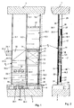
- the climate module P 1 is used to introduce fresh air into a room
- the climate module P 2 is used to introduce heated or cooled air.
- Both climate modules are located between a ceiling 1 and a floor 2 of a room. On the floor 2 there is still a structure 3, wherein in Spaces 4 lines are led for a heating or cooling medium.
- the air conditioning module P 2 is connected to the ceiling 1 via hanging profiles 5.1 and 5.2 and can stand up on the structure 3. For acoustic reasons, however, it is provided that the climate module P 2 maintains a slight distance from the body 3.
- climate modules P 1 and P 2 are laterally covered or separated from one another by metal stand structures, sealing strips, joint expansion tapes or plasterboard strips 6.1 to 6.3.
- a heat exchanger 7 which consists of two areas 7.1 and 7.2.
- the area 7.1 is connected via a supply line 8 to a heating flow and via a return line 9 to a heating return.
- a supply line 10 to the area 7.2 serves as a cold water supply and a return line 11 as a cold water return.
- Adjustable shut-off valves 12 and 13 are switched on in the feed lines 8 and 10.
- other valves can be seen, but are not described in detail.
- the cables can also run in suspended ceilings.
- the heat exchanger 7 consists essentially of tubes 37 and transversely thereto running fins 38.
- the heating or cooling medium is in the tube 37 guided and the fins 38 essentially form the heat exchanger surfaces. It should be emphasized that the slats 38 in the direction of the air flow run so that noise when flowing through is minimized.
- a Cross-flow fan 14 can be seen, which is driven by a motor 15. Above this cross-flow fan 14 is a Plate silencer 16.1, also another plate silencer 16.2 provided below the heat exchanger 7. In every plate silencer 16.1 and 16.2, a throughflow channel 17 can be seen, which has a step 18 formed. For this purpose, each plate silencer 16.1 and 16.2 a shorter rear panel 19, the opposite of a longer front panel 20 is arranged. Back plate 19 and front plate 20 have about that same thickness. An end plate 21 then closes on the front plate 20 a greater thickness, so that between the front panel 20 and the End plate 21 is a step 22 is formed. This level 22 is preferably from a sheet, for example a steel sheet 23.
- a mineral wool layer 28 behind the climate module P2 which is covered with a terodem film 29 towards the climate module P 2 .
- the mineral wool layer 28 is preceded by two gypsum plasterboards 30.1 and 30.2.
- the climate module P 2 is covered towards the front by a gypsum plasterboard, not shown, only the suction openings 25 and the exhaust openings 27 being left free.
- a gypsum plasterboard not shown, only the suction openings 25 and the exhaust openings 27 being left free.
- several plasterboard panels can also be provided for a wall.
- the entire air conditioning module P 2 is designed to be very flat, so that it can be inserted into a metal stud wall without difficulty. Air is drawn in by the crossflow fan 14 through the suction openings 25 and the flow channel 17 of the plate muffler 16.2. This air also passes through the heat exchanger 7 and can be cooled or heated as desired.
- the climate module P 1 serves exclusively to supply fresh air into a room.
- three fresh air connections 31.1 to 31.3 are provided, which open into a filter chamber 32.
- This filter chamber 32 is followed by a plate silencer 16.3, which is followed by two pumps or fans 33.1 and 33.2, both fans 33.1 and 33.2 being driven by a motor 34.
- the air conveyed then in turn flows through a plate silencer 16.4 and is pressed out of an outlet opening 35.
- Three further fresh air channels 36.1 to 36.3 are intended to show that this air conditioning module P 1 can also supply fresh air to three other rooms.
Landscapes
- Engineering & Computer Science (AREA)
- Chemical & Material Sciences (AREA)
- Combustion & Propulsion (AREA)
- Mechanical Engineering (AREA)
- General Engineering & Computer Science (AREA)
- Physics & Mathematics (AREA)
- Thermal Sciences (AREA)
- Building Environments (AREA)
- Duct Arrangements (AREA)
- Central Air Conditioning (AREA)
Abstract
Description
| 1 | Decke | 34 | Motor | 67 | |
| 2 | Boden | 35 | Auslassöffnung | 68 | |
| 3 | Aufbau | 36 | Frischluftkanal | 69 | |
| 4 | Zwischenraum | 37 | Röhrchen | 70 | |
| 5 | Hängeprofil | 38 | Lamellen | 71 | |
| 6 | Gipskartonstreifen | 39 | 72 | ||
| 7 | Wärmetauscher | 40 | 73 | ||
| 8 | Zuleitung | 41 | 74 | ||
| 9 | Rückleitung | 42 | 75 | ||
| 10 | Zuleitung | 43 | 76 | ||
| 11 | Rückleitung | 44 | 77 | ||
| 12 | Absperrventil | 45 | 78 | ||
| 13 | Absperrventil | 46 | 79 | ||
| 14 | Querstromventilator | 47 | |||
| 15 | Motor | 48 | |||
| 16 | Plattenschalldämpfer | 49 | |||
| 17 | Durchströmkanal | 50 | |||
| 18 | Stufe | 51 | P | Klimamodul | |
| 19 | Rückseitenplatte | 52 | |||
| 20 | Frontplatte | 53 | |||
| 21 | Endplatte | 54 | |||
| 22 | Stufe | 55 | |||
| 23 | Blech | 56 | |||
| 24 | Ansaugraum | 57 | |||
| 25 | Ansaugöffnung | 58 | |||
| 26 | Ausblaskammer | 59 | |||
| 27 | Ausblasöffnung | 60 | |||
| 28 | Mineralwollschicht | 61 | |||
| 29 | Folie | 62 | |||
| 30 | Gipskartonplatte | 63 | |||
| 31 | Frischlauftanschluss | 64 | |||
| 32 | Filterraum | 65 | |||
| 33 | Ventilator | 66 |
Claims (18)
- Anlage zum Temperieren eines Raumes durch Zuführen und/oder Abführen von frischer, gekühlter und/oder erwärmter Luft und/oder von Umluft,
dadurch gekennzeichnet, dass ein Klimamodul (P1, P2) in Flachbauweise erstellt und einer Wand, Aussenfassade einer Decke (1) oder einem Boden (2) des Raumes zugeordnet ist. - Anlage zum Temperieren eines Raumes durch Zuführen und/oder Abführen von frischer, gekühlter und/oder erwärmter Luft und/oder von Umluft, dadurch gekennzeichnet, dass in einem Klimamodul (P1, P2) zumindest ein Plattenschalldämpfer (16.1 - 16.4) vorgesehen ist, dessen Durchströmkanal (17) eine Stufe (18) ausbildet.
- Anlage nach Anspruch 2, dadurch gekennzeichnet, dass der Plattenschalldämpfer (16.1 - 16.4) aus Schaumstoff auf Melaminharzbasis besteht.
- Anlage nach Anspruch 3, dadurch gekennzeichnet, dass eine kürzere Platte (19) eine Rückseite des Plattenschalldämpfers (16.1 - 16.4) bildet, der unter Ausbildung des Durchströmkanals (17) eine Frontplatte (20) ähnlicher Dicke vorgesetzt ist, an die sich nach dem Ende der Rückseitenplatte (19) eine Endplatte (21) grösserer Dicke anschliesst.
- Anlage nach Anspruch 4, dadurch gekennzeichnet, dass am Übergang von Frontplatte (20) und Endplatte (21) ein Blech (23) in den Plattenschalldämpfer (16.1 - 16.4) eingesetzt ist.
- Anlage nach wenigstens einem der Ansprüche 1 bis 5, dadurch gekennzeichnet, dass das Klimamodul (P1, P2) über ein Hängeprofil (5.1, 5.2) mit der Decke (1) verbunden ist.
- Anlage nach wenigstens einem der Ansprüche 1 bis 6, dadurch gekennzeichnet, dass das Klimamodul (P1, P2) in eine Raumtrennwand mit geringer Einbautiefe, beispielsweise eine Metallständerwand, integriert ist.
- Anlage nach wenigstens einem der Ansprüche 1 bis 7, dadurch gekennzeichnet, dass in dem Klimamodul (P2) zumindest ein Wärmetauscher (7) vorgesehen ist.
- Anlage nach Anspruch 8, dadurch gekennzeichnet, dass der Wärmetauscher aus Lamellen und die Lamellen kreuzenden, ein Temperiermedium führenden Leitungen besteht.
- Anlage nach Anspruch 9, dadurch gekennzeichnet, dass die Lamellen in Strömungsrichtung der Luft angeordnet sind.
- Anlage nach wenigstens einem der Ansprüche 8 bis 10, dadurch gekennzeichnet, dass der Wärmetauscher (7) zwischen zwei Plattenschalldämpfer (16.1, 16.2) angeordnet ist.
- Anlage nach wengistens einem der Ansprüche 8 bis 11, dadurch gekennzeichnet, dass dem Wärmetauscher (7) ein Ventilator (14), vorzugsweise ein Querstromventilator, zugeordnet ist.
- Anlage nach wenigstens einem der Ansprüche 8 bis 12, dadurch gekennzeichnet, dass der Wärmetauscher (7) einen Bereich (7.1), der mit einem Heizmedium in Verbindung steht, und einen Bereich (7.2) aufweist, der von einem Kühlmedium versorgt ist.
- Anlage nach wenigstens einem der Ansprüche 1 bis 13, dadurch gekennzeichnet, dass das Klimamodul (P2) zumindest eine Ansaugöffnung (25) für Raumluft und zumindest eine Auslassöffnung (27) für temperierte Luft aufweist.
- Anlage nach Anspruch 14, dadurch gekennzeichnet, dass den Auslassöffnungen (27) verstellbare Lamellen zugeordnet sind.
- Anlage nach wenigstens einem der Ansprüche 1 bis 15, dadurch gekennzeichnet, dass in dem Klimamodul (P1) eine Ansaugeinrichtung (33.1, 33.2) für Frischluft angeordnet ist.
- Anlage nach Anspruch 16, dadurch gekennzeichnet, dass sich die Ansaugeinrichtung (33.1, 33.2) zwischen zwei Plattenschalldämpfern (16.3, 16.4) befindet.
- Anlage nach Anspruch 17, dadurch gekennzeichnet, dass dem ansaugseitigen Plattenschalldämpfer (16.3) ein Filter (32) vorgeschaltet ist.
Applications Claiming Priority (4)
| Application Number | Priority Date | Filing Date | Title |
|---|---|---|---|
| DE10302325A DE10302325A1 (de) | 2003-01-20 | 2003-01-20 | Anlage zum Temperieren eines Raumes |
| DE10302325 | 2003-01-20 | ||
| DE10302704A DE10302704B4 (de) | 2003-01-23 | 2003-01-23 | Anlage zum Temperieren eines Raumes |
| DE10302704 | 2003-01-23 |
Publications (2)
| Publication Number | Publication Date |
|---|---|
| EP1441184A1 true EP1441184A1 (de) | 2004-07-28 |
| EP1441184B1 EP1441184B1 (de) | 2012-01-04 |
Family
ID=32598098
Family Applications (1)
| Application Number | Title | Priority Date | Filing Date |
|---|---|---|---|
| EP04000405A Expired - Lifetime EP1441184B1 (de) | 2003-01-20 | 2004-01-12 | Anlage zum Temperieren eines Raumes |
Country Status (3)
| Country | Link |
|---|---|
| EP (1) | EP1441184B1 (de) |
| AT (1) | ATE540272T1 (de) |
| ES (1) | ES2380192T3 (de) |
Cited By (5)
| Publication number | Priority date | Publication date | Assignee | Title |
|---|---|---|---|---|
| EP1655547A1 (de) * | 2004-11-05 | 2006-05-10 | SCHAKO Klima Luft Ferdinand Schad KG | Vorrichtung zum Temperieren von Luft in einem Raum |
| DE102018111720A1 (de) * | 2018-05-16 | 2019-07-11 | Viessmann Werke Gmbh & Co Kg | Gebäudeaußenwandabschnitt zum Verschließen einer Fassadenöffnung |
| EP4428464A1 (de) | 2023-03-07 | 2024-09-11 | Schako KG | Schalldämpfungsvorrichtung für eine belüftungsanlage |
| DE102024106314A1 (de) | 2023-03-07 | 2024-09-12 | SCHAKO KG Zweigniederlassung Kolbingen | Schalldämpfungsvorrichtung für eine Belüftungsanlage |
| IT202300020004A1 (it) * | 2023-09-28 | 2025-03-28 | Kataltherm Service Sa | Porta o costruzione architettonica |
Families Citing this family (1)
| Publication number | Priority date | Publication date | Assignee | Title |
|---|---|---|---|---|
| CN105780943B (zh) * | 2016-03-07 | 2018-03-23 | 江西理工大学 | 一种多层建筑辐射换热空调墙体 |
Citations (9)
| Publication number | Priority date | Publication date | Assignee | Title |
|---|---|---|---|---|
| DE2308479A1 (de) | 1973-02-21 | 1974-09-05 | Henrik Torsten Witt | Lueftungselement |
| FR2567628A1 (fr) * | 1984-07-16 | 1986-01-17 | Od Proizv Obiedi | Installation pour l'epuration de l'air et l'admission d'air epure dans un local |
| DE3720554A1 (de) * | 1987-06-22 | 1989-01-05 | Gerhard Herzog | Plattenfoermiges bauelement |
| FR2700203A1 (fr) * | 1993-01-04 | 1994-07-08 | Cherrier Gerard | Unité autonome de diffusion d'air propre à flux laminaire destinée aux chambres dites "stériles" et aux volumes propres. |
| DE19738474A1 (de) * | 1996-09-04 | 1998-04-30 | Krukenbaum Uwe | Luftfiltereinheit zur Reinigung der Raumluft und Heizkörperverkleidung |
| DE19723485A1 (de) * | 1997-06-05 | 1998-12-10 | Schwarz Michael | Vorrichtung zum Be- und Entlüften von Räumen |
| DE20114240U1 (de) * | 2001-08-29 | 2002-01-24 | Ruoff, Michael, 71111 Waldenbuch | Schalldämpfer für Lüftermotoren |
| DE10104923C1 (de) * | 2001-01-25 | 2002-10-02 | Lta Lufttechnische Komponenten | Brandschutzklappe für Lüftungssysteme |
| DE10128379A1 (de) * | 2001-06-07 | 2003-01-02 | Ds Plan Ingenieurgesellschaft | Vorrichtung zur dezentralen Belüftung eines Raumes und Lüftungsanlage für mehrere Räume |
-
2004
- 2004-01-12 EP EP04000405A patent/EP1441184B1/de not_active Expired - Lifetime
- 2004-01-12 ES ES04000405T patent/ES2380192T3/es not_active Expired - Lifetime
- 2004-01-12 AT AT04000405T patent/ATE540272T1/de active
Patent Citations (9)
| Publication number | Priority date | Publication date | Assignee | Title |
|---|---|---|---|---|
| DE2308479A1 (de) | 1973-02-21 | 1974-09-05 | Henrik Torsten Witt | Lueftungselement |
| FR2567628A1 (fr) * | 1984-07-16 | 1986-01-17 | Od Proizv Obiedi | Installation pour l'epuration de l'air et l'admission d'air epure dans un local |
| DE3720554A1 (de) * | 1987-06-22 | 1989-01-05 | Gerhard Herzog | Plattenfoermiges bauelement |
| FR2700203A1 (fr) * | 1993-01-04 | 1994-07-08 | Cherrier Gerard | Unité autonome de diffusion d'air propre à flux laminaire destinée aux chambres dites "stériles" et aux volumes propres. |
| DE19738474A1 (de) * | 1996-09-04 | 1998-04-30 | Krukenbaum Uwe | Luftfiltereinheit zur Reinigung der Raumluft und Heizkörperverkleidung |
| DE19723485A1 (de) * | 1997-06-05 | 1998-12-10 | Schwarz Michael | Vorrichtung zum Be- und Entlüften von Räumen |
| DE10104923C1 (de) * | 2001-01-25 | 2002-10-02 | Lta Lufttechnische Komponenten | Brandschutzklappe für Lüftungssysteme |
| DE10128379A1 (de) * | 2001-06-07 | 2003-01-02 | Ds Plan Ingenieurgesellschaft | Vorrichtung zur dezentralen Belüftung eines Raumes und Lüftungsanlage für mehrere Räume |
| DE20114240U1 (de) * | 2001-08-29 | 2002-01-24 | Ruoff, Michael, 71111 Waldenbuch | Schalldämpfer für Lüftermotoren |
Cited By (6)
| Publication number | Priority date | Publication date | Assignee | Title |
|---|---|---|---|---|
| EP1655547A1 (de) * | 2004-11-05 | 2006-05-10 | SCHAKO Klima Luft Ferdinand Schad KG | Vorrichtung zum Temperieren von Luft in einem Raum |
| DE102018111720A1 (de) * | 2018-05-16 | 2019-07-11 | Viessmann Werke Gmbh & Co Kg | Gebäudeaußenwandabschnitt zum Verschließen einer Fassadenöffnung |
| EP4428464A1 (de) | 2023-03-07 | 2024-09-11 | Schako KG | Schalldämpfungsvorrichtung für eine belüftungsanlage |
| DE102024106314A1 (de) | 2023-03-07 | 2024-09-12 | SCHAKO KG Zweigniederlassung Kolbingen | Schalldämpfungsvorrichtung für eine Belüftungsanlage |
| IT202300020004A1 (it) * | 2023-09-28 | 2025-03-28 | Kataltherm Service Sa | Porta o costruzione architettonica |
| WO2025068975A1 (en) * | 2023-09-28 | 2025-04-03 | Kataltherm Service Sa | Door or architectural construction comprising a fancoil |
Also Published As
| Publication number | Publication date |
|---|---|
| ES2380192T3 (es) | 2012-05-09 |
| ATE540272T1 (de) | 2012-01-15 |
| EP1441184B1 (de) | 2012-01-04 |
Similar Documents
| Publication | Publication Date | Title |
|---|---|---|
| EP0044560B1 (de) | Belüftungsanlage für im Zwangsumlauf belüftete Räume | |
| EP2450520B1 (de) | Kontrolliertes Lüftungssytem für ein Gebäude mittels eines Türelements | |
| DE102016120554A1 (de) | Multifunktionale Deckenkonstruktion | |
| EP1441184B1 (de) | Anlage zum Temperieren eines Raumes | |
| EP1411303A1 (de) | Raumtemperierungselement und dessen Anordnung | |
| DE10302704B4 (de) | Anlage zum Temperieren eines Raumes | |
| EP2210992A2 (de) | Thermoaktive Fertigteilplatte mit Akustikabsorber | |
| EP2791436B1 (de) | Gebäude mit einem in eine betondecke des gebäudes integrierten raumkonditionierungssystem zum kühlen, heizen und zur belüftung | |
| DE102007027839A1 (de) | Modulares Lüftungssystem | |
| EP1624258A2 (de) | Einrichtung zur Raumlüftung und Einbaumodul zur Raumlüftung | |
| DE10302325A1 (de) | Anlage zum Temperieren eines Raumes | |
| CN115095942A (zh) | 一种房间内设有卫生间的双向流全屋新风系统 | |
| DE10128379A1 (de) | Vorrichtung zur dezentralen Belüftung eines Raumes und Lüftungsanlage für mehrere Räume | |
| EP2965016A1 (de) | Aktive überströmanordnung | |
| DE202010017413U1 (de) | Zentralklimaanlage sowie Schalldämpfmittel für eine Zentralklimaanlage | |
| EP1431675A2 (de) | Anordnung zur Raumklimatisierung | |
| DE212020000567U1 (de) | Gesteuertes mechanisches Ventilationssystem mit Luftmischeinheit | |
| DE2915494A1 (de) | Reckuperative waermerueckgewinnung bei statischen heizungen | |
| DE19845557A1 (de) | Luftzirkulationsheizsystem in der Dämmerung mit Einbringung der Raumentlüftung und eine technische Anlage zum Betreiben mit Nutzung von Alternativ-, und Verlustenergien | |
| AT500559B1 (de) | Raumlufttechnische einrichtung | |
| DE19738172C1 (de) | Einrichtung zum Temperieren von Gebäuden | |
| EP1139031A2 (de) | Innenraum-Klimatisierungsvorrichtung | |
| DE10316431B4 (de) | Klimaeinrichtung ausgebildet als dezentrales Gerät | |
| EP2557369A2 (de) | Vorrichtung zum Klimatisieren eines Innenraums und zugehöriges Verfahren | |
| DE102007005870B4 (de) | Wandelement |
Legal Events
| Date | Code | Title | Description |
|---|---|---|---|
| PUAI | Public reference made under article 153(3) epc to a published international application that has entered the european phase |
Free format text: ORIGINAL CODE: 0009012 |
|
| AK | Designated contracting states |
Kind code of ref document: A1 Designated state(s): AT BE BG CH CY CZ DE DK EE ES FI FR GB GR HU IE IT LI LU MC NL PT RO SE SI SK TR |
|
| AX | Request for extension of the european patent |
Extension state: AL LT LV MK |
|
| 17P | Request for examination filed |
Effective date: 20040814 |
|
| AKX | Designation fees paid |
Designated state(s): AT BE BG CH CY CZ DE DK EE ES FI FR GB GR HU IE IT LI LU MC NL PT RO SE SI SK TR |
|
| 17Q | First examination report despatched |
Effective date: 20070221 |
|
| GRAP | Despatch of communication of intention to grant a patent |
Free format text: ORIGINAL CODE: EPIDOSNIGR1 |
|
| GRAS | Grant fee paid |
Free format text: ORIGINAL CODE: EPIDOSNIGR3 |
|
| GRAA | (expected) grant |
Free format text: ORIGINAL CODE: 0009210 |
|
| AK | Designated contracting states |
Kind code of ref document: B1 Designated state(s): AT BE BG CH CY CZ DE DK EE ES FI FR GB GR HU IE IT LI LU MC NL PT RO SE SI SK TR |
|
| REG | Reference to a national code |
Ref country code: GB Ref legal event code: FG4D Free format text: NOT ENGLISH |
|
| REG | Reference to a national code |
Ref country code: CH Ref legal event code: EP |
|
| REG | Reference to a national code |
Ref country code: AT Ref legal event code: REF Ref document number: 540272 Country of ref document: AT Kind code of ref document: T Effective date: 20120115 |
|
| REG | Reference to a national code |
Ref country code: IE Ref legal event code: FG4D |
|
| REG | Reference to a national code |
Ref country code: CH Ref legal event code: NV Representative=s name: ARIE WUBBEN |
|
| REG | Reference to a national code |
Ref country code: DE Ref legal event code: R096 Ref document number: 502004013192 Country of ref document: DE Effective date: 20120301 |
|
| REG | Reference to a national code |
Ref country code: NL Ref legal event code: T3 |
|
| PGFP | Annual fee paid to national office [announced via postgrant information from national office to epo] |
Ref country code: LU Payment date: 20120306 Year of fee payment: 9 Ref country code: FR Payment date: 20120329 Year of fee payment: 9 |
|
| REG | Reference to a national code |
Ref country code: CH Ref legal event code: PCAR Free format text: ARIE WUBBEN C/O ALTAMURA GMBH;BAHNHOFSTRASSE 31;8280 KREUZLINGEN (CH) |
|
| REG | Reference to a national code |
Ref country code: ES Ref legal event code: FG2A Ref document number: 2380192 Country of ref document: ES Kind code of ref document: T3 Effective date: 20120509 |
|
| PG25 | Lapsed in a contracting state [announced via postgrant information from national office to epo] |
Ref country code: SI Free format text: LAPSE BECAUSE OF FAILURE TO SUBMIT A TRANSLATION OF THE DESCRIPTION OR TO PAY THE FEE WITHIN THE PRESCRIBED TIME-LIMIT Effective date: 20120104 |
|
| REG | Reference to a national code |
Ref country code: HU Ref legal event code: AG4A Ref document number: E013231 Country of ref document: HU |
|
| PGFP | Annual fee paid to national office [announced via postgrant information from national office to epo] |
Ref country code: GB Payment date: 20120322 Year of fee payment: 9 |
|
| PG25 | Lapsed in a contracting state [announced via postgrant information from national office to epo] |
Ref country code: BG Free format text: LAPSE BECAUSE OF FAILURE TO SUBMIT A TRANSLATION OF THE DESCRIPTION OR TO PAY THE FEE WITHIN THE PRESCRIBED TIME-LIMIT Effective date: 20120404 |
|
| PGFP | Annual fee paid to national office [announced via postgrant information from national office to epo] |
Ref country code: HU Payment date: 20120314 Year of fee payment: 9 Ref country code: NL Payment date: 20120326 Year of fee payment: 9 |
|
| REG | Reference to a national code |
Ref country code: IE Ref legal event code: FD4D |
|
| PG25 | Lapsed in a contracting state [announced via postgrant information from national office to epo] |
Ref country code: FI Free format text: LAPSE BECAUSE OF FAILURE TO SUBMIT A TRANSLATION OF THE DESCRIPTION OR TO PAY THE FEE WITHIN THE PRESCRIBED TIME-LIMIT Effective date: 20120104 Ref country code: GR Free format text: LAPSE BECAUSE OF FAILURE TO SUBMIT A TRANSLATION OF THE DESCRIPTION OR TO PAY THE FEE WITHIN THE PRESCRIBED TIME-LIMIT Effective date: 20120405 Ref country code: MC Free format text: LAPSE BECAUSE OF NON-PAYMENT OF DUE FEES Effective date: 20120131 Ref country code: PT Free format text: LAPSE BECAUSE OF FAILURE TO SUBMIT A TRANSLATION OF THE DESCRIPTION OR TO PAY THE FEE WITHIN THE PRESCRIBED TIME-LIMIT Effective date: 20120504 |
|
| PG25 | Lapsed in a contracting state [announced via postgrant information from national office to epo] |
Ref country code: CY Free format text: LAPSE BECAUSE OF FAILURE TO SUBMIT A TRANSLATION OF THE DESCRIPTION OR TO PAY THE FEE WITHIN THE PRESCRIBED TIME-LIMIT Effective date: 20120104 |
|
| PGFP | Annual fee paid to national office [announced via postgrant information from national office to epo] |
Ref country code: IT Payment date: 20120327 Year of fee payment: 9 |
|
| PG25 | Lapsed in a contracting state [announced via postgrant information from national office to epo] |
Ref country code: CZ Free format text: LAPSE BECAUSE OF FAILURE TO SUBMIT A TRANSLATION OF THE DESCRIPTION OR TO PAY THE FEE WITHIN THE PRESCRIBED TIME-LIMIT Effective date: 20120104 Ref country code: IE Free format text: LAPSE BECAUSE OF FAILURE TO SUBMIT A TRANSLATION OF THE DESCRIPTION OR TO PAY THE FEE WITHIN THE PRESCRIBED TIME-LIMIT Effective date: 20120104 Ref country code: DK Free format text: LAPSE BECAUSE OF FAILURE TO SUBMIT A TRANSLATION OF THE DESCRIPTION OR TO PAY THE FEE WITHIN THE PRESCRIBED TIME-LIMIT Effective date: 20120104 Ref country code: RO Free format text: LAPSE BECAUSE OF FAILURE TO SUBMIT A TRANSLATION OF THE DESCRIPTION OR TO PAY THE FEE WITHIN THE PRESCRIBED TIME-LIMIT Effective date: 20120104 Ref country code: SE Free format text: LAPSE BECAUSE OF FAILURE TO SUBMIT A TRANSLATION OF THE DESCRIPTION OR TO PAY THE FEE WITHIN THE PRESCRIBED TIME-LIMIT Effective date: 20120104 Ref country code: EE Free format text: LAPSE BECAUSE OF FAILURE TO SUBMIT A TRANSLATION OF THE DESCRIPTION OR TO PAY THE FEE WITHIN THE PRESCRIBED TIME-LIMIT Effective date: 20120104 |
|
| PLBE | No opposition filed within time limit |
Free format text: ORIGINAL CODE: 0009261 |
|
| STAA | Information on the status of an ep patent application or granted ep patent |
Free format text: STATUS: NO OPPOSITION FILED WITHIN TIME LIMIT |
|
| PG25 | Lapsed in a contracting state [announced via postgrant information from national office to epo] |
Ref country code: SK Free format text: LAPSE BECAUSE OF FAILURE TO SUBMIT A TRANSLATION OF THE DESCRIPTION OR TO PAY THE FEE WITHIN THE PRESCRIBED TIME-LIMIT Effective date: 20120104 |
|
| 26N | No opposition filed |
Effective date: 20121005 |
|
| REG | Reference to a national code |
Ref country code: DE Ref legal event code: R097 Ref document number: 502004013192 Country of ref document: DE Effective date: 20121005 |
|
| PGFP | Annual fee paid to national office [announced via postgrant information from national office to epo] |
Ref country code: AT Payment date: 20120313 Year of fee payment: 9 |
|
| PGFP | Annual fee paid to national office [announced via postgrant information from national office to epo] |
Ref country code: ES Payment date: 20120327 Year of fee payment: 9 |
|
| REG | Reference to a national code |
Ref country code: NL Ref legal event code: V1 Effective date: 20130801 |
|
| REG | Reference to a national code |
Ref country code: AT Ref legal event code: MM01 Ref document number: 540272 Country of ref document: AT Kind code of ref document: T Effective date: 20130131 |
|
| GBPC | Gb: european patent ceased through non-payment of renewal fee |
Effective date: 20130112 |
|
| REG | Reference to a national code |
Ref country code: FR Ref legal event code: ST Effective date: 20130930 |
|
| PG25 | Lapsed in a contracting state [announced via postgrant information from national office to epo] |
Ref country code: NL Free format text: LAPSE BECAUSE OF NON-PAYMENT OF DUE FEES Effective date: 20130801 Ref country code: HU Free format text: LAPSE BECAUSE OF NON-PAYMENT OF DUE FEES Effective date: 20130113 Ref country code: AT Free format text: LAPSE BECAUSE OF NON-PAYMENT OF DUE FEES Effective date: 20130131 |
|
| PG25 | Lapsed in a contracting state [announced via postgrant information from national office to epo] |
Ref country code: GB Free format text: LAPSE BECAUSE OF NON-PAYMENT OF DUE FEES Effective date: 20130112 Ref country code: FR Free format text: LAPSE BECAUSE OF NON-PAYMENT OF DUE FEES Effective date: 20130131 |
|
| PG25 | Lapsed in a contracting state [announced via postgrant information from national office to epo] |
Ref country code: IT Free format text: LAPSE BECAUSE OF NON-PAYMENT OF DUE FEES Effective date: 20130112 |
|
| REG | Reference to a national code |
Ref country code: ES Ref legal event code: FD2A Effective date: 20140321 |
|
| PG25 | Lapsed in a contracting state [announced via postgrant information from national office to epo] |
Ref country code: TR Free format text: LAPSE BECAUSE OF FAILURE TO SUBMIT A TRANSLATION OF THE DESCRIPTION OR TO PAY THE FEE WITHIN THE PRESCRIBED TIME-LIMIT Effective date: 20120104 |
|
| PG25 | Lapsed in a contracting state [announced via postgrant information from national office to epo] |
Ref country code: ES Free format text: LAPSE BECAUSE OF NON-PAYMENT OF DUE FEES Effective date: 20130113 |
|
| REG | Reference to a national code |
Ref country code: DE Ref legal event code: R082 Ref document number: 502004013192 Country of ref document: DE Representative=s name: PATENTANWAELTE UND RECHTSANWALT DR. WEISS, ARA, DE Ref country code: DE Ref legal event code: R082 Ref document number: 502004013192 Country of ref document: DE Representative=s name: PATENTANWAELTE UND RECHTSANWALT WEISS, ARAT & , DE |
|
| PG25 | Lapsed in a contracting state [announced via postgrant information from national office to epo] |
Ref country code: LU Free format text: LAPSE BECAUSE OF NON-PAYMENT OF DUE FEES Effective date: 20130112 |
|
| REG | Reference to a national code |
Ref country code: CH Ref legal event code: PCAR Free format text: NEW ADDRESS: MUEHLENTALSTRASSE 186, 8200 SCHAFFHAUSEN (CH) |
|
| REG | Reference to a national code |
Ref country code: DE Ref legal event code: R081 Ref document number: 502004013192 Country of ref document: DE Owner name: SCHAKO KG, DE Free format text: FORMER OWNER: SCHAKO KLIMA LUFT FERDINAND SCHAD KG ZWEIGNIEDERLASSUNG KOLBINGEN, 78600 KOLBINGEN, DE |
|
| REG | Reference to a national code |
Ref country code: BE Ref legal event code: PD Owner name: SCHAKO KG; DE Free format text: DETAILS ASSIGNMENT: CHANGE OF OWNER(S), OTHER; FORMER OWNER NAME: SCHAKO KLIMA LUFT FERDINAND SCHAD KG Effective date: 20220804 |
|
| PGFP | Annual fee paid to national office [announced via postgrant information from national office to epo] |
Ref country code: CH Payment date: 20230222 Year of fee payment: 20 |
|
| PGFP | Annual fee paid to national office [announced via postgrant information from national office to epo] |
Ref country code: DE Payment date: 20230329 Year of fee payment: 20 Ref country code: BE Payment date: 20230125 Year of fee payment: 20 |
|
| REG | Reference to a national code |
Ref country code: DE Ref legal event code: R071 Ref document number: 502004013192 Country of ref document: DE |
|
| REG | Reference to a national code |
Ref country code: CH Ref legal event code: PL |
|
| REG | Reference to a national code |
Ref country code: BE Ref legal event code: MK Effective date: 20240112 |