EP1442883A1 - Cylindre de serrage pour tendre un cliché de gaufrage sur un rouleau de gaufrage - Google Patents
Cylindre de serrage pour tendre un cliché de gaufrage sur un rouleau de gaufrage Download PDFInfo
- Publication number
- EP1442883A1 EP1442883A1 EP04001327A EP04001327A EP1442883A1 EP 1442883 A1 EP1442883 A1 EP 1442883A1 EP 04001327 A EP04001327 A EP 04001327A EP 04001327 A EP04001327 A EP 04001327A EP 1442883 A1 EP1442883 A1 EP 1442883A1
- Authority
- EP
- European Patent Office
- Prior art keywords
- clamping
- sleeve
- clamping sleeve
- compressed air
- shaft
- Prior art date
- Legal status (The legal status is an assumption and is not a legal conclusion. Google has not performed a legal analysis and makes no representation as to the accuracy of the status listed.)
- Withdrawn
Links
- 238000004049 embossing Methods 0.000 title claims abstract description 51
- 238000005496 tempering Methods 0.000 claims abstract description 25
- 238000000034 method Methods 0.000 claims abstract description 9
- 239000012530 fluid Substances 0.000 claims description 38
- 229910052782 aluminium Inorganic materials 0.000 claims description 7
- XAGFODPZIPBFFR-UHFFFAOYSA-N aluminium Chemical compound [Al] XAGFODPZIPBFFR-UHFFFAOYSA-N 0.000 claims description 7
- 230000008569 process Effects 0.000 claims description 6
- 229910000838 Al alloy Inorganic materials 0.000 claims description 3
- 239000011248 coating agent Substances 0.000 claims description 3
- 238000000576 coating method Methods 0.000 claims description 3
- 238000007599 discharging Methods 0.000 claims description 2
- 238000007639 printing Methods 0.000 description 11
- 239000004922 lacquer Substances 0.000 description 6
- 230000008859 change Effects 0.000 description 5
- 238000005516 engineering process Methods 0.000 description 5
- 239000000463 material Substances 0.000 description 5
- 238000007789 sealing Methods 0.000 description 5
- IJGRMHOSHXDMSA-UHFFFAOYSA-N Atomic nitrogen Chemical compound N#N IJGRMHOSHXDMSA-UHFFFAOYSA-N 0.000 description 4
- 230000008901 benefit Effects 0.000 description 4
- 238000004519 manufacturing process Methods 0.000 description 4
- 125000006850 spacer group Chemical group 0.000 description 4
- 238000001816 cooling Methods 0.000 description 3
- 229920001187 thermosetting polymer Polymers 0.000 description 3
- PXHVJJICTQNCMI-UHFFFAOYSA-N Nickel Chemical compound [Ni] PXHVJJICTQNCMI-UHFFFAOYSA-N 0.000 description 2
- 230000004323 axial length Effects 0.000 description 2
- 230000006835 compression Effects 0.000 description 2
- 238000007906 compression Methods 0.000 description 2
- 229910052757 nitrogen Inorganic materials 0.000 description 2
- 230000000717 retained effect Effects 0.000 description 2
- 239000000758 substrate Substances 0.000 description 2
- XLYOFNOQVPJJNP-UHFFFAOYSA-N water Substances O XLYOFNOQVPJJNP-UHFFFAOYSA-N 0.000 description 2
- 239000000919 ceramic Substances 0.000 description 1
- 150000001875 compounds Chemical class 0.000 description 1
- 238000010276 construction Methods 0.000 description 1
- 230000008878 coupling Effects 0.000 description 1
- 238000010168 coupling process Methods 0.000 description 1
- 238000005859 coupling reaction Methods 0.000 description 1
- 238000004132 cross linking Methods 0.000 description 1
- 230000001419 dependent effect Effects 0.000 description 1
- 238000011161 development Methods 0.000 description 1
- 230000018109 developmental process Effects 0.000 description 1
- 238000011010 flushing procedure Methods 0.000 description 1
- 239000011888 foil Substances 0.000 description 1
- 230000010354 integration Effects 0.000 description 1
- 210000001503 joint Anatomy 0.000 description 1
- 239000007788 liquid Substances 0.000 description 1
- 230000007246 mechanism Effects 0.000 description 1
- 229910052751 metal Inorganic materials 0.000 description 1
- 239000002184 metal Substances 0.000 description 1
- 229910052759 nickel Inorganic materials 0.000 description 1
- 238000005192 partition Methods 0.000 description 1
- 238000006116 polymerization reaction Methods 0.000 description 1
- 230000008092 positive effect Effects 0.000 description 1
- 238000003847 radiation curing Methods 0.000 description 1
- 239000007787 solid Substances 0.000 description 1
- 239000011343 solid material Substances 0.000 description 1
- 238000004381 surface treatment Methods 0.000 description 1
- 238000010792 warming Methods 0.000 description 1
Images

Classifications
-
- B—PERFORMING OPERATIONS; TRANSPORTING
- B44—DECORATIVE ARTS
- B44B—MACHINES, APPARATUS OR TOOLS FOR ARTISTIC WORK, e.g. FOR SCULPTURING, GUILLOCHING, CARVING, BRANDING, INLAYING
- B44B5/00—Machines or apparatus for embossing decorations or marks, e.g. embossing coins
- B44B5/0004—Machines or apparatus for embossing decorations or marks, e.g. embossing coins characterised by the movement of the embossing tool(s), or the movement of the work, during the embossing operation
- B44B5/0009—Rotating embossing tools
-
- B—PERFORMING OPERATIONS; TRANSPORTING
- B41—PRINTING; LINING MACHINES; TYPEWRITERS; STAMPS
- B41F—PRINTING MACHINES OR PRESSES
- B41F13/00—Common details of rotary presses or machines
- B41F13/08—Cylinders
- B41F13/22—Means for cooling or heating forme or impression cylinders
-
- B—PERFORMING OPERATIONS; TRANSPORTING
- B41—PRINTING; LINING MACHINES; TYPEWRITERS; STAMPS
- B41F—PRINTING MACHINES OR PRESSES
- B41F27/00—Devices for attaching printing elements or formes to supports
- B41F27/10—Devices for attaching printing elements or formes to supports for attaching non-deformable curved printing formes to forme cylinders
- B41F27/105—Devices for attaching printing elements or formes to supports for attaching non-deformable curved printing formes to forme cylinders for attaching cylindrical printing formes
-
- B—PERFORMING OPERATIONS; TRANSPORTING
- B41—PRINTING; LINING MACHINES; TYPEWRITERS; STAMPS
- B41P—INDEXING SCHEME RELATING TO PRINTING, LINING MACHINES, TYPEWRITERS, AND TO STAMPS
- B41P2227/00—Mounting or handling printing plates; Forming printing surfaces in situ
- B41P2227/20—Means enabling or facilitating exchange of tubular printing or impression members, e.g. printing sleeves, blankets
- B41P2227/21—Means facilitating exchange of sleeves mounted on cylinders without removing the cylinder from the press
-
- F—MECHANICAL ENGINEERING; LIGHTING; HEATING; WEAPONS; BLASTING
- F28—HEAT EXCHANGE IN GENERAL
- F28F—DETAILS OF HEAT-EXCHANGE AND HEAT-TRANSFER APPARATUS, OF GENERAL APPLICATION
- F28F5/00—Elements specially adapted for movement
- F28F5/02—Rotary drums or rollers
Definitions
- the invention relates to a clamping cylinder and a method for clamping cylindrical embossing dies for embossing rollers, especially for Embossing diffractive gratings or holograms on plastic foils and other substrates.
- embossing forms have a partial or all-over structured surface, which after the embossing shape on the clamping cylinder was clamped into a rotating endless process Embossing lacquer is molded. Because the lacquer layer that is embossed is relatively thin, preferably "endless" embossing forms used that neither a butt edge or butt joint nor a bulky Show seam.
- Tensioning cylinders for similar purposes are known from printing technology. Indeed are those used there and clamped on the clamping cylinder Printing plates thick-walled and very solid, so that the clamping cylinder mechanically because of the high clamping forces that occur during clamping is adjusted accordingly. For example, in printing technology flexible printing forms made of rubber-like materials, the other clamping mechanisms require used. In some printing processes come too thin metallic plates are used as printing form, e.g. magnetic and be excited.
- embossing diffractive gratings and holograms are suitable for tension cylinders from printing technology therefore not, because those used for stamping, usually made of nickel Manufactured embossing molds lie as so-called tubular, thin-walled "Sleeves" with a wall thickness of just a few tenths of a millimeter.
- the thin-walled sleeve can be clamped onto the clamping cylinder according to different principles.
- the clamping cylinder or at least its outer, cylindrical adapter sleeve cooled from the inside, for example by continuous Flushing with liquid nitrogen.
- the clamping cylinder or the clamping sleeve consist of a material with a high coefficient of thermal expansion, for example aluminum so that its outer diameter is due the cooling shrinks accordingly.
- the cylindrical Pull the sleeve slightly over the clamping cylinder or the clamping sleeve.
- the diameter expands Warming back to its original value. This way the surface of the clamping cylinder or the clamping sleeve in immediate Contact with the sleeve and tighten it.
- This principle is for example mentioned in DE 100 49 283 A1.
- the sleeve becomes elastic by means of compressed air expanded, being between the clamping cylinder surface and the sleeve An air cushion is created, over which the sleeve easily on the clamping cylinder can be postponed and removed from it.
- the compressed air is switched off, the sleeve contracts radially on the surface of the clamping cylinder to the system, causing it is firmly clamped on the surface.
- tempering the dies for embossing diffractive gratings and holograms from essential in order to emboss the optically diffractive structures to achieve a good transfer and a good embossing result Usually not tempered is tempering the dies for embossing diffractive gratings and holograms from essential in order to emboss the optically diffractive structures to achieve a good transfer and a good embossing result.
- embossed in radiation-curing lacquers it may be necessary to remove heat of polymerization to overheat the substrate to avoid.
- thermosetting lacquers heat may be required. That is why adequate tempering is necessary of the sleeve for embossing optically diffractive structures of special Importance.
- DE 100 39 744 A1 uses instead of one for thermosetting systems external heat supply an internal tempering of the embossing mold ("sleeve") proposed in which the embossing shape from the inside during the embossing process is brought to an optimally determined temperature.
- the one described there Clamping cylinder includes a hollow shaft, an adapter sleeve with an outer surface for clamping the cylindrical embossing mold and two end brackets for fixing the adapter sleeve coaxially the wave.
- the adapter sleeve is clamped from the inside using a temperature in particular water, tempered, which through a first channel of the hollow Shaft into a cavity between the shaft and the adapter sleeve passed and through a second channel that is coaxial with the first channel in the hollow shaft is arranged, led out of the cavity again becomes.
- a temperature in particular water, tempered which through a first channel of the hollow Shaft into a cavity between the shaft and the adapter sleeve passed and through a second channel that is coaxial with the first channel in the hollow shaft is arranged, led out of the cavity again becomes.
- a compressed air supply line to the shaft Integrated shaft.
- the compressed air is radial in the front bracket Branches and through pipelines, which are in the Extend the cavity between the shaft and the adapter sleeve in the axial direction, to different ones that extend radially through the adapter sleeve Through holes forwarded.
- Through the through holes the compressed air at different points on the surface of the adapter sleeve off, so that a compressed air cushion is created, through which a to be clamped Embossing die is expanded radially and on which the embossing die slightly pushed over the adapter sleeve and pulled off again can be.
- the object of the present invention is to provide a structurally simple design Clamping cylinder that can be temperature-controlled from the inside on the one hand and that on the other easily from one die to another die, in particular with different diameters, can be converted and a process to propose for cylindrical embossing dies.
- the embossing shape or the sleeve for Pushing on and pulling off is expanded using compressed air
- that the compressed air lines run in the adapter sleeve.
- a line system in the adapter sleeve between at least one Compressed air inlet opening and the radial compressed air outlet openings in the axial and / or tangential direction.
- the exchange of the adapter sleeve is made considerably easier.
- the entire clamping cylinder does not need to be replaced, if only an adapter sleeve with a larger outer diameter for Clamping an embossing mold of larger diameter is to be used.
- the drive shaft and the fixing device for fixing the clamping sleeve coaxial to the drive shaft can be maintained.
- the compressed air supply line can pass through the drive shaft and further in the radial direction through the holder for fixing the Guide the adapter sleeve on the drive shaft to the adapter sleeve, similar to that in the principle described in DE 100 39 744 A1.
- a preferred production technology Embodiment of the invention provides that the compressed air inlet opening is located on an axial end face of the adapter sleeve. The Compressed air can then be used to change the embossing shape using flexible hoses be introduced into the front connection.
- the adapter sleeve can be pushed on and pulled off if the clamping cylinder is designed so that the clamping sleeve is a total of this can be solved, as is the case, for example, in DE 10102 269 A1 Swinging out a bearing of the clamping cylinder shaft is proposed.
- the line system for the compressed air lines can be used as a duct system be realized in the adapter sleeve.
- the term "sewer system" in the present sense means a pipe system which is made of solid material the adapter sleeve is integrated. Such a duct system can, for example drilled into the adapter sleeve, which is a simple hollow cylinder his.
- the adapter sleeve can also be used by two coaxial and direct adjacent hollow cylinders can be formed, in which the Channel system in the inner surface of the outer hollow cylinder and / or milled into the outer surface of the inner hollow cylinder is.
- the clamping sleeve is double-walled Hollow cylinder formed, the line system for the Compressed air lines as a pipe system in the between the cylinder walls formed space is realized.
- the piping system can be constructed similarly to that described in DE 100 39 744 A1 In contrast, the pipe system is located within the Adapter sleeve and is therefore easy when changing the format removed from the drive shaft together with the adapter sleeve.
- the latter variant in which the adapter sleeve is double-walled Hollow cylinder is formed can be effectively with a temperature control can be combined, namely by the space between the two cylinder walls for receiving a temperature control fluid is being used.
- the outer hollow cylinder of the adapter sleeve can be on this Way over its entire surface by means of that directed into the intermediate space Temperature control fluids tempered from the inside to an optimal temperature become.
- the temperature control device in the space be implemented as a pipe system between the two cylinder walls, through which the temperature control fluid is passed.
- the heat transfer from the temperature control fluid to the outer hollow cylinder In this case, the adapter sleeve is less effective and in particular distributed irregularly over the surface.
- the adapter sleeve is a full body in which the compressed air lines is integrated as a duct system, as explained above, so can also be used in a corresponding manner for the lines for the temperature control fluid be implemented as a duct system.
- the temperature control device in the clamping sleeve to integrate itself, but, as described in DE 100 39 744 A1, the cavity between the shaft and the adapter sleeve in the axial direction seal to accommodate the tempering fluid in this cavity.
- the shaft can be drilled hollow for the tempering fluid feed and discharge.
- the shaft preferably comprises separate ones Inlets and outlets so that the temperature control fluid is continuous can flow through the cavity.
- the temperature of the outer adapter sleeve surface depends only insignificantly from the thickness of the adapter sleeve. That is, with one Format change from a cylindrical embossing form (sleeve) with a comparatively small diameter on an embossing mold with a comparatively large diameter only needs a thin-walled adapter sleeve to be exchanged for a correspondingly thick-walled adapter sleeve, without affecting the tempering of the adapter sleeve surface has a significant impact.
- the structure of the shaft is much less complicated, which affects the manufacturing cost and stability of the shaft has a positive effect.
- the temperature control fluid must be in front of you Exchange of an adapter sleeve with another adapter sleeve is not out of the system be emptied, since the system when using suitable, in particular self-closing valves is hermetically sealed.
- the Integration of the temperature control device in the adapter sleeve since only the inlet and outlet connections have to be sealed, what by means of suitable valves. Sealing the cavity between the shaft and the adapter sleeve for receiving a temperature control fluid in contrast, is much more complex.
- clamping jaws can be mounted on the shaft serve to fix the adapter sleeve, as it is related below is explained with a second variant of the invention.
- the second variant according to the invention relates to a clamping cylinder in which the sleeve is mechanically expanded in order to close it on the clamping cylinder fix.
- the fixing device is not only used for fixing the adapter sleeve on the shaft.
- the adapter sleeve is by means of Fixing device expanded radially so far that not only the clamping sleeve clamped on the fixing device, but that also over the adapter sleeve pushed sleeve clamped on the thus expanded clamping sleeve.
- the expansion sleeve is expanded by means of commercially available pressure sleeves not always possible, but at best in the case of very thin walls Clamping sleeves. It is therefore more suitable as a fixing device for this second one variant of the invention the use of jaws. With jaws Much larger mechanical forces can be applied radially from the inside Apply the adapter sleeve.
- the expansion of adapter sleeves of different thicknesses with approximately the same inner diameter becomes particularly simple as a result that the same clamping jaws for clamping sleeves with different outside diameters are usable. For other diameter ranges, the Jaws exchanged for appropriately adjusted jaws become. This means that all desired sleeve diameters can be used with one shaft be driven by either only the adapter sleeve or the adapter sleeve is replaced with the jaws.
- the tempering of the adapter sleeve can be implemented in the same way, as described in relation to the first variant of the invention.
- the Means there can either be a cavity between the shaft and the adapter sleeve be flushed with a temperature control fluid, a hollow one being drilled Shaft for supplying and discharging the tempering fluid.
- the temperature control device is integrated into the adapter sleeve itself, in shape of cooling coils, channels, bores or the like, as previously explained.
- the adapter sleeve is preferably made of aluminum or an aluminum alloy.
- Aluminum combines some essential material properties, by having a high coefficient of thermal conductivity.
- aluminum is comparatively elastic, which makes the Elastic sleeve can be expanded elastically without much effort in order to open it Tighten the sleeve.
- aluminum can be Its low strength makes it easy to machine so that the fine adjustment of the outer diameter of the adapter sleeve in a simple manner Turning off the outer surface can be done.
- the outermost surface of the adapter sleeve is preferably surface-treated, to protect them against mechanical damage when pulling on the sleeves protect.
- the surface treatment is preferably a coating with mechanically hard material, such as Sintered metal, ceramic compounds etc.
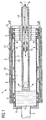
- FIG. 1 shows a clamping cylinder according to a first embodiment of the first variant according to the invention.
- the representation in Figure 1 gives the construction only schematically again, insignificant for the invention Components are not shown.
- the clamping cylinder 1 includes one Drive shaft 2 and an adapter sleeve 3, which on two shaft shoulders 4 with expanded diameter is clamped by means of fixing devices 5.
- the fixing device 5 is designed here as a pressure sleeve and works on the principle that axial compression of the pressure sleeve is radial Expansion causes the same.
- the axial compression force is determined by a schematically shown adjusting nut 6 to that shown in Figure 1 on the left Pressure sleeve 5 applied and by means of a spacer tube 7 on the opposite shaft end arranged pressure sleeve 5 transmitted, so that both pressure sleeves 5 axially to the same extent by means of the adjusting nut 6 compressed and thereby expanded radially.
- the adapter sleeve 3 can be placed on the printing sleeves with or without a sleeve 5 are pushed on and by tightening the adjusting nut 6 with the pressure sleeves 5 clamped and thus fixed on the shaft 2. In reverse In this way, the adapter sleeve 3 can be pulled off the shaft 2 again become.
- the clamping cylinder 1 With the sleeve clamped onto the clamping sleeve 3 (not shown in FIG. 1) can the clamping cylinder 1 in an embossing system as an embossing roller or embossing cylinder be used.
- the sleeve can be pulled onto the clamping sleeve 3 be mounted before or after the adapter sleeve on shaft 2 becomes.
- a compressed air line system is in the clamping sleeve 3 8 with one or more compressed air inlet openings 9 on one end of the Collet 3 and with distributed over the surface 10 of the collet 3 radial compressed air outlet openings 11 are provided.
- the front Compressed air inlet openings 9 have a connection system, not shown for connecting a compressed air supply line.
- the sleeve is pushed onto the clamping sleeve 3 widened by the compressed air emerging from the clamping sleeve surface 10 and can be on the between the sleeve and the collet 3 Air cushion created in a simple manner on the clamping sleeve 3. After switching off the compressed air, there is a good, flat contact between the clamping sleeve 3 and the drawn sleeve, whereby the sleeve is fixed by friction on the clamping sleeve 3.
- Compressed air in the sense of the present invention is any gaseous Understand medium that is suitable for the purposes described above is.
- the clamping sleeve 3 by two pressure sleeves 5 at the two axial ends of the clamping sleeve 3 fixed.
- the adapter sleeve 3 is cooled from the inside by means of a temperature control fluid.
- the first embodiment of the first invention according to the invention shown in FIG Variant an axially sealed cavity 12 between the shaft 2 and the adapter sleeve 3 through which a temperature control fluid for example water. So that the cavity 12 does not is separated from the adapter sleeve 3 by the spacer tube 7, has the spacer tube 7 numerous passages 13 through which the tempering fluid in Contact with the inner surface of the adapter sleeve 3.
- the current of the temperature control fluid is indicated by arrows in FIG. 1.
- the tempering fluid is one Passed end of the cavity 12, flows through the cavity 12 and is again discharged through the hollow drilled shaft 2 coaxially to the feed line 14.
- a seal 15 in the hollow shaft 2 is provided to one Prevent flow short-circuit.
- the clamping sleeve 3 is preferably made of aluminum, an aluminum alloy or another material with a high coefficient of thermal conductivity, around a sleeve stretched on the clamping sleeve surface 10 as effectively as possible by means of the temperature control fluid flowing through the cavity 12 to temper, that is, either to cool, if, for example is embossed in exotic cross-linking lacquers, or to heat, when embossing in thermosetting lacquers.
- the heat is in the Adapter sleeve 3 well guided due to their small wall thickness, so that when Operation of the embossing system a rapid tempering is achieved. The operating point the system is reached quickly, wasted time during start-up are minimized.
- the supply and discharge of the temperature control fluid is not done by one shown two-way rotor sealing head, on the corresponding side the drive shaft is mounted.
- a rotor sealing head as well as the Pressure sleeves 5 are common, commercially available purchased parts.
- the adapter sleeve 3 In the event of a format change to a sleeve with a different diameter only needs the adapter sleeve 3 against an adapter sleeve with the corresponding Outside diameter to be replaced without changing the shaft 2 must be removed from the embossing system.
- the Adapter sleeve 3 are withdrawn from the shaft 2 in the manner in which DE 101 02 269 A1 mentioned at the beginning is explained by only one Shaft end, meaningfully the end away from the rotor sealing head, the shaft 2 is swung out.
- Only the inside diameter of the Adapter sleeves are determined by the geometry of the fixing device.
- the Outside diameter can be selected within a certain range as long as it is effective Heat transfer through the adapter sleeve is possible.
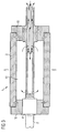
- FIG. 2 shows a second embodiment of a clamping cylinder according to the first variant according to the invention.
- This second embodiment is opposite the embodiment of Figure 1 optimized to the extent that constructive effort for the temperature control is reduced and the temperature control is also more effective.
- the clamping sleeve 3 is clamped on the pressure sleeves 5, which are through a spacer tube 7 are spaced apart and by means of an adjusting nut 6 be axially compressed so that they expand radially to accommodate this Way the sliding sleeve 3 pushed over it on the shaft shoulders 4 Clamp shaft 2.
- the clamping sleeve 3 has at least a feed opening 16 and at least one discharge opening 17 for Supply and discharge of the temperature control fluid.
- Wave 2 is only in one hollow at the front and has coaxial feed and discharge lines 14, 18, which in turn leads to a two-way rotor sealing head, not shown to lead.
- the temperature control fluid is supplied from the supply line 14 and the discharge line 18 outside of the clamping cylinder 1, for example, by flexible Hoses, which are only indicated schematically by broken lines in FIG are fed to the feed opening 16 of the clamping sleeve 3 or from the discharge opening 17 of the adapter sleeve 3 returned to the shaft 2.
- the feed and discharge openings 16, 17 are preferably in the form of quick coupling valves executed that automatically in the uncoupled state conclude.
- the sleeve is pulled onto the clamping sleeve 3, as in the exemplary embodiment according to FIG. 1, by means of compressed air via a clamping sleeve 3 Integrated compressed air line system, which is not explicitly shown in Figure 2 is.
- the clamping sleeve 3 can be constructed in various ways his.
- the clamping sleeve 3 is a hollow cylinder formed, including two or more coaxially pushed into each other Hollow cylinders are to be understood, their outside and inside diameters are adjusted accordingly. Be in this hollow cylinder then the compressed air and temperature control fluid line systems as sewer line systems integrated, for example milled or drilled into it.
- the adapter sleeve consists of a double-walled one Hollow cylinder, both the compressed air line system and the tempering fluid line system as a pipe system in the space are realized between the two cylinder walls.
- the tempering fluid line system can, for example, by one or more Tempering lines are formed.
- the clamping sleeve 3 in turn consists of a double-walled hollow cylinder, but only the compressed air lines in the space between the two cylinder walls as Piping system are realized and the space from the rest of is flowed through the tempering fluid essentially unhindered.
- Partitions can be provided in the intermediate space, which have a chamber-like or labyrinthine, in particular meandering guidance of the temperature control fluid through the space from the feed opening 16 to Drain opening 17 guarantee a flow short between Avoid feed and discharge opening 16, 17.
- the temperature of the clamping sleeve surface 10 is that shown in FIG. 2
- Adapter sleeve 3 can be adjusted particularly quickly because, in contrast to The embodiment according to FIG. 1 does not temper the entire shaft, but only the adapter sleeve 3. This makes the film stamping a stationary one Operating status reached more quickly.
- Figure 3 shows an embodiment according to the second variant of the invention.
- the main difference to the embodiments according to figures 1 and 2 consists in the way of stretching a sleeve the clamping sleeve 3.
- the sleeves are not expanded by compressed air to them to be able to slide over the adapter sleeve 3, but rather has Adapter sleeve 3 initially has a smaller diameter at ambient temperature than the sleeve, so that the sleeve easily fits onto the adapter sleeve 3 can be raised. Only then is the adapter sleeve 3 by means of Clamping jaws 19 radially widened so that the one pushed onto the clamping sleeve 3 Sleeve is stuck.
- the jaws 19 perform two functions.
- the first function consists in tightening the jaws 19, the clamping sleeve 3 on the Shaft heels 4 to fix the shaft 2 mechanically, and the further function is by further tightening the jaws 19, the clamping sleeve 3 to expand - as described above - one to the Fix sleeve 3 slid on sleeve.
- the temperature of the clamping sleeve 3 is carried out in the same way as in relation was explained on the embodiment of Figure 1 by a Tempering fluid through the hollow shaft 2 and a cavity 12 is rinsed between the adapter sleeve 3 and the shaft 2.
- a Tempering fluid through the hollow shaft 2 and a cavity 12 is rinsed between the adapter sleeve 3 and the shaft 2.
- the adapter sleeve 3 directly from a tempering fluid are flowed through, analogously to the embodiment according to FIG. 2.
- clamping jaws 19 instead of the clamping jaws 19, other clamping or fixing devices can also be used are used, for example those in relation to FIGS. 1 and 2 mentioned clamping sleeves, provided there are enough radial forces on the Collet 3 can be applied to the collet to the desired extent dilate.
Landscapes
- Engineering & Computer Science (AREA)
- Mechanical Engineering (AREA)
- Shaping Of Tube Ends By Bending Or Straightening (AREA)
- Shaping Metal By Deep-Drawing, Or The Like (AREA)
Applications Claiming Priority (2)
| Application Number | Priority Date | Filing Date | Title |
|---|---|---|---|
| DE10304117 | 2003-01-31 | ||
| DE10304117A DE10304117A1 (de) | 2003-01-31 | 2003-01-31 | Spannzylinder zum Aufspannen zylindrischer Prägeformen für Prägewalzen |
Publications (1)
| Publication Number | Publication Date |
|---|---|
| EP1442883A1 true EP1442883A1 (fr) | 2004-08-04 |
Family
ID=32603099
Family Applications (1)
| Application Number | Title | Priority Date | Filing Date |
|---|---|---|---|
| EP04001327A Withdrawn EP1442883A1 (fr) | 2003-01-31 | 2004-01-22 | Cylindre de serrage pour tendre un cliché de gaufrage sur un rouleau de gaufrage |
Country Status (3)
| Country | Link |
|---|---|
| US (1) | US6874415B2 (fr) |
| EP (1) | EP1442883A1 (fr) |
| DE (1) | DE10304117A1 (fr) |
Cited By (9)
| Publication number | Priority date | Publication date | Assignee | Title |
|---|---|---|---|---|
| WO2007068878A1 (fr) * | 2005-12-13 | 2007-06-21 | Gew (Ec) Limited | Rouleau refroidi par air |
| DE102007062123A1 (de) | 2007-12-21 | 2009-06-25 | Giesecke & Devrient Gmbh | Werkzeugform zum Erzeugen einer Mikrostruktur |
| EP2090432A1 (fr) | 2008-02-12 | 2009-08-19 | Müller Martini Holding AG | Cylindre pour une unité d'impression et procédé d'échange d'un manchon d'impression d'un tel cylindre |
| EP1721742A3 (fr) * | 2005-05-13 | 2011-01-19 | Wetzel GmbH | Calandre de gaufrage |
| WO2011015480A1 (fr) * | 2009-08-04 | 2011-02-10 | Kba-Metronic Aktiengesellschaft | Douille d'un cylindre |
| DE102010036011A1 (de) * | 2010-08-31 | 2012-03-01 | Heidelberger Druckmaschinen Ag | Braillehülse |
| WO2013160191A1 (fr) * | 2012-04-26 | 2013-10-31 | Spm Steuer Gmbh & Co. Kg | Cylindre d'outil comprenant un manchon d'outil interchangeable et estampeuse ou presse à imprimer comprenant un tel cylindre d'outil |
| WO2016087047A1 (fr) * | 2014-12-04 | 2016-06-09 | Bobst Mex Sa | Mandrin d'outil rotatif, groupe de transformation d'un support plan, et procede de fonctionnement |
| CN114571839A (zh) * | 2022-02-21 | 2022-06-03 | 温州鸣旭机械科技有限公司 | 一种贴合度高的柔印设备及印刷方法 |
Families Citing this family (20)
| Publication number | Priority date | Publication date | Assignee | Title |
|---|---|---|---|---|
| ITFI20010223A1 (it) * | 2001-11-26 | 2003-05-26 | Perini Fabio Spa | Cilindro goffratore con camicia intercambiabile e con sistema di bloccaggio frontale della camicia, e gruppo goffratore comprendente detto |
| DE10331943A1 (de) * | 2003-07-15 | 2005-02-17 | Nexpress Solutions Llc | Verfahren zum Wechseln einer Manschette an einem Zylinder und Zylinder mit einer Manschette |
| ITFI20040107A1 (it) * | 2004-05-05 | 2004-08-05 | Perini Fabio Spa | Rullo a camicia intercambiabile per gruppi goffratori e gruppo goffratore comprendente tale rullo |
| DE102004022181B3 (de) * | 2004-05-05 | 2005-11-03 | Man Roland Druckmaschinen Ag | Vorrichtung zum Verbinden einer inneren Druckhülse mit einer äußeren Druckhülse zu einer Einheit und zum Trennen der beiden Druckhülsen |
| US7124685B2 (en) * | 2004-05-18 | 2006-10-24 | Meca & Technology Machine, Inc. | Internally piped print cylinder and method for making same |
| JP5005907B2 (ja) * | 2004-11-11 | 2012-08-22 | ハイデルベルガー ドルツクマシーネン アクチエンゲゼルシヤフト | 印刷機 |
| DE102006005151A1 (de) * | 2006-02-04 | 2007-08-09 | Man Roland Druckmaschinen Ag | Vorrichtung und Verfahren zum Temperieren eines Rotationskörpers |
| US20080229941A1 (en) * | 2007-03-19 | 2008-09-25 | Babak Heidari | Nano-imprinting apparatus and method |
| DE102007000507B4 (de) * | 2007-10-15 | 2010-03-11 | Koenig & Bauer Aktiengesellschaft | Walze eines Trockners |
| IT1402297B1 (it) * | 2010-09-08 | 2013-08-28 | Uteco Converting Spa | Struttura di cilindro retinato particolarmente per macchine da stampa flessografiche |
| CN102653161A (zh) * | 2012-05-09 | 2012-09-05 | 中国人民银行印制科学技术研究所 | 一种印刷滚筒 |
| US8915185B2 (en) * | 2012-09-05 | 2014-12-23 | Bunting Magnetics Co. | Assembly for axially aligning a print die |
| US9341213B2 (en) * | 2012-10-19 | 2016-05-17 | Frc Holding Corp. | Quick release roller sleeve mounting hub |
| US9162439B2 (en) * | 2013-07-18 | 2015-10-20 | Bunting Magnetics Co. | Printing assembly |
| US9381470B2 (en) * | 2013-10-25 | 2016-07-05 | Shanghai Honghao Enterprise Development CO., LTD | Coating equipment for a composite membrane without a diffusion pump and its thickness gauge for both thick and thin coatings |
| EP3723986B1 (fr) * | 2017-12-13 | 2021-08-18 | Flint Group Germany GmbH | Adaptateur de serrage pneumatique |
| EP3921162B1 (fr) | 2019-02-05 | 2023-03-15 | Koenig & Bauer AG | Unité d'impression en creux à imprimer du substrat selon un procédé d'impression en creux |
| DE102019103789A1 (de) | 2019-02-05 | 2020-08-06 | Koenig & Bauer Ag | Druckwerk und Druckmaschine mit einem Druckwerk |
| CN113619263A (zh) * | 2021-09-23 | 2021-11-09 | 嘉兴百思蓝德包装股份有限公司 | 一种服装吊牌用数字彩色无水胶印用冷却辊装置 |
| CN116732700B (zh) * | 2022-03-04 | 2025-08-19 | 奥美医疗(湖北)防护用品有限公司 | 非织造布轧花装置和方法 |
Citations (4)
| Publication number | Priority date | Publication date | Assignee | Title |
|---|---|---|---|---|
| DE250448C (fr) * | ||||
| US5819657A (en) * | 1996-03-11 | 1998-10-13 | Ermino Rossini, Spa | Air carrier spacer sleeve for a printing cylinder |
| DE19846033A1 (de) * | 1998-10-06 | 2000-04-13 | Windmoeller & Hoelscher | Druckmaschine |
| DE10039744A1 (de) | 2000-08-16 | 2002-02-28 | Hueck Folien Gmbh & Co Kg | Spannzylinder |
Family Cites Families (4)
| Publication number | Priority date | Publication date | Assignee | Title |
|---|---|---|---|---|
| US3753276A (en) * | 1971-12-27 | 1973-08-21 | K Reisch | Calender roll cover |
| CA2277146A1 (fr) * | 1997-01-13 | 1998-07-16 | Randy L. Mittelstaedt | Rouleau chauffe a caloducs integres |
| JP3884957B2 (ja) * | 1999-10-08 | 2007-02-21 | ケーニツヒ ウント バウエル アクチエンゲゼルシヤフト | 輪転印刷機の胴 |
| US6377772B1 (en) * | 2000-10-04 | 2002-04-23 | Nexpress Solutions Llc | Double-sleeved electrostatographic roller and method of using |
-
2003
- 2003-01-31 DE DE10304117A patent/DE10304117A1/de not_active Withdrawn
-
2004
- 2004-01-22 US US10/761,429 patent/US6874415B2/en not_active Expired - Fee Related
- 2004-01-22 EP EP04001327A patent/EP1442883A1/fr not_active Withdrawn
Patent Citations (4)
| Publication number | Priority date | Publication date | Assignee | Title |
|---|---|---|---|---|
| DE250448C (fr) * | ||||
| US5819657A (en) * | 1996-03-11 | 1998-10-13 | Ermino Rossini, Spa | Air carrier spacer sleeve for a printing cylinder |
| DE19846033A1 (de) * | 1998-10-06 | 2000-04-13 | Windmoeller & Hoelscher | Druckmaschine |
| DE10039744A1 (de) | 2000-08-16 | 2002-02-28 | Hueck Folien Gmbh & Co Kg | Spannzylinder |
Cited By (11)
| Publication number | Priority date | Publication date | Assignee | Title |
|---|---|---|---|---|
| EP1721742A3 (fr) * | 2005-05-13 | 2011-01-19 | Wetzel GmbH | Calandre de gaufrage |
| WO2007068878A1 (fr) * | 2005-12-13 | 2007-06-21 | Gew (Ec) Limited | Rouleau refroidi par air |
| DE102007062123A1 (de) | 2007-12-21 | 2009-06-25 | Giesecke & Devrient Gmbh | Werkzeugform zum Erzeugen einer Mikrostruktur |
| WO2009083148A3 (fr) * | 2007-12-21 | 2010-01-21 | Giesecke & Devrient Gmbh | Matrice-outil permettant de réaliser une microstructure |
| EP2090432A1 (fr) | 2008-02-12 | 2009-08-19 | Müller Martini Holding AG | Cylindre pour une unité d'impression et procédé d'échange d'un manchon d'impression d'un tel cylindre |
| WO2011015480A1 (fr) * | 2009-08-04 | 2011-02-10 | Kba-Metronic Aktiengesellschaft | Douille d'un cylindre |
| DE102010036011A1 (de) * | 2010-08-31 | 2012-03-01 | Heidelberger Druckmaschinen Ag | Braillehülse |
| WO2013160191A1 (fr) * | 2012-04-26 | 2013-10-31 | Spm Steuer Gmbh & Co. Kg | Cylindre d'outil comprenant un manchon d'outil interchangeable et estampeuse ou presse à imprimer comprenant un tel cylindre d'outil |
| WO2016087047A1 (fr) * | 2014-12-04 | 2016-06-09 | Bobst Mex Sa | Mandrin d'outil rotatif, groupe de transformation d'un support plan, et procede de fonctionnement |
| US10464276B2 (en) | 2014-12-04 | 2019-11-05 | Bobst Mex Sa | Rotary-tool mandrel, unit for converting a flat substrate, and operating method |
| CN114571839A (zh) * | 2022-02-21 | 2022-06-03 | 温州鸣旭机械科技有限公司 | 一种贴合度高的柔印设备及印刷方法 |
Also Published As
| Publication number | Publication date |
|---|---|
| US6874415B2 (en) | 2005-04-05 |
| US20040255804A1 (en) | 2004-12-23 |
| DE10304117A1 (de) | 2004-08-05 |
Similar Documents
| Publication | Publication Date | Title |
|---|---|---|
| EP1442883A1 (fr) | Cylindre de serrage pour tendre un cliché de gaufrage sur un rouleau de gaufrage | |
| EP1584389B1 (fr) | Dispositif de serrage expansible | |
| DE102010004426A1 (de) | Vorrichtung zum Aufweiten von Hohlkörpern | |
| DE10250686A1 (de) | Verfahren zum Temperieren eines Ballens eines Rotationskörpers einer Druckmaschine und Rotationskörper einer Druckmaschine mit einem Ballen | |
| EP2153917A2 (fr) | Dispositif d'agrandissement pour tuyaux et raccord de serrage pour tuyaux | |
| DE20012929U1 (de) | Adapterhülse, insbesondere für Druckmaschinen | |
| DE9017016U1 (de) | Einstellbare Befestigungsvorrichtung | |
| EP4117849B1 (fr) | Procédé de production de joints soudés entre des tubes internes et des plaques porte-tube d'un faisceau tubulaire pour un échangeur de chaleur à faisceau tubulaire de type produit à produit au moyen d'un dispositif auxiliaire, et dispositif auxiliaire conçu pour un tel procédé de production | |
| DE9000980U1 (de) | Walze für ein Glättwerk oder einen Kalander | |
| DE102009060785A1 (de) | Koaxialventil mit Dichtelement | |
| WO2000010809A1 (fr) | Dispositif de retenue pour manchons d'impression flexographique | |
| DE2166908B2 (de) | Kunststoffwarmverformungsmaschine zum Tiefziehen von einseitig offenen Hohlkörpern | |
| EP4378662B1 (fr) | Procédé et dispositif pour la fabrication de tubes enroulés en matière plastique, en particulier de tubes d'entrefer pour pompes à rotor humide | |
| EP2050971B1 (fr) | Composant hydraulique avec tirant segmenté | |
| DE10250690B4 (de) | Rotationskörper einer Druckmaschine mit einem Ballen | |
| DE3312073C2 (de) | Druckaufbaudorn zum druckdichten Befestigen eines Rohres | |
| EP1815981A2 (fr) | Dispositif et procédé pour réguler la température d'un élément rotatif | |
| EP0440140A2 (fr) | Rouleau pour appareil de lissage ou calandre | |
| DE102016201691A1 (de) | Flüssigkeitsgekühlte elektrische Maschine für ein Kraftfahrzeug | |
| WO2006053857A1 (fr) | Echangeur thermique haute pression a faisceau de tubes | |
| EP1480808B1 (fr) | Dispositif de fermeture monte sur une machine de moulage a injection de matiere plastique | |
| EP1725351B1 (fr) | Procede de production d'une conduite fluidique, notamment d'une conduite fluidique dans une installation frigorifique au co sb 2 /sb | |
| DE3118038C2 (fr) | ||
| DE102008000044A1 (de) | Werkzeugkühlsystem | |
| EP1529964B1 (fr) | Dispositif de couplage hydraulique |
Legal Events
| Date | Code | Title | Description |
|---|---|---|---|
| PUAI | Public reference made under article 153(3) epc to a published international application that has entered the european phase |
Free format text: ORIGINAL CODE: 0009012 |
|
| AK | Designated contracting states |
Kind code of ref document: A1 Designated state(s): AT BE BG CH CY CZ DE DK EE ES FI FR GB GR HU IE IT LI LU MC NL PT RO SE SI SK TR |
|
| AX | Request for extension of the european patent |
Extension state: AL LT LV MK |
|
| 17P | Request for examination filed |
Effective date: 20050204 |
|
| AKX | Designation fees paid |
Designated state(s): AT BE BG CH CY CZ DE DK EE ES FI FR GB GR HU IE IT LI LU MC NL PT RO SE SI SK TR |
|
| AXX | Extension fees paid |
Extension state: MK Payment date: 20050204 Extension state: LV Payment date: 20050204 Extension state: LT Payment date: 20050204 Extension state: AL Payment date: 20050204 |
|
| 17Q | First examination report despatched |
Effective date: 20081216 |
|
| STAA | Information on the status of an ep patent application or granted ep patent |
Free format text: STATUS: THE APPLICATION IS DEEMED TO BE WITHDRAWN |
|
| 18D | Application deemed to be withdrawn |
Effective date: 20110802 |