EP1445531A2 - Safety device, particularly for industrial machines, such as bending presses - Google Patents
Safety device, particularly for industrial machines, such as bending presses Download PDFInfo
- Publication number
- EP1445531A2 EP1445531A2 EP04002216A EP04002216A EP1445531A2 EP 1445531 A2 EP1445531 A2 EP 1445531A2 EP 04002216 A EP04002216 A EP 04002216A EP 04002216 A EP04002216 A EP 04002216A EP 1445531 A2 EP1445531 A2 EP 1445531A2
- Authority
- EP
- European Patent Office
- Prior art keywords
- glove
- safety device
- tool
- conducting regions
- regions
- Prior art date
- Legal status (The legal status is an assumption and is not a legal conclusion. Google has not performed a legal analysis and makes no representation as to the accuracy of the status listed.)
- Granted
Links
- 238000005452 bending Methods 0.000 title claims abstract description 16
- 239000004020 conductor Substances 0.000 claims description 5
- 230000005540 biological transmission Effects 0.000 claims description 4
- 239000000463 material Substances 0.000 claims description 4
- 238000000465 moulding Methods 0.000 claims description 4
- 238000004026 adhesive bonding Methods 0.000 claims description 2
- 239000007769 metal material Substances 0.000 claims description 2
- 239000003973 paint Substances 0.000 claims description 2
- 238000009958 sewing Methods 0.000 claims description 2
- 238000004804 winding Methods 0.000 claims description 2
- 230000004913 activation Effects 0.000 claims 1
- 238000000151 deposition Methods 0.000 claims 1
- 238000001514 detection method Methods 0.000 claims 1
- 230000007257 malfunction Effects 0.000 claims 1
- 239000002184 metal Substances 0.000 abstract description 6
- 238000003754 machining Methods 0.000 description 2
- 238000004519 manufacturing process Methods 0.000 description 2
- 230000007423 decrease Effects 0.000 description 1
- 230000000670 limiting effect Effects 0.000 description 1
- 230000004048 modification Effects 0.000 description 1
- 238000012986 modification Methods 0.000 description 1
- 230000009467 reduction Effects 0.000 description 1
- 238000005482 strain hardening Methods 0.000 description 1
- 238000002604 ultrasonography Methods 0.000 description 1
- 210000000707 wrist Anatomy 0.000 description 1
Images


Classifications
-
- A—HUMAN NECESSITIES
- A41—WEARING APPAREL
- A41D—OUTERWEAR; PROTECTIVE GARMENTS; ACCESSORIES
- A41D19/00—Gloves
- A41D19/0055—Plastic or rubber gloves
- A41D19/0082—Details
- A41D19/0096—Means for resisting mechanical agressions, e.g. cutting or piercing
-
- A—HUMAN NECESSITIES
- A41—WEARING APPAREL
- A41D—OUTERWEAR; PROTECTIVE GARMENTS; ACCESSORIES
- A41D19/00—Gloves
-
- A—HUMAN NECESSITIES
- A41—WEARING APPAREL
- A41D—OUTERWEAR; PROTECTIVE GARMENTS; ACCESSORIES
- A41D19/00—Gloves
- A41D19/015—Protective gloves
- A41D19/01505—Protective gloves resistant to mechanical aggressions, e.g. cutting. piercing
- A41D19/01517—Protective gloves resistant to mechanical aggressions, e.g. cutting. piercing with protection against crushing, e.g. of the finger tips
-
- A—HUMAN NECESSITIES
- A41—WEARING APPAREL
- A41D—OUTERWEAR; PROTECTIVE GARMENTS; ACCESSORIES
- A41D19/00—Gloves
- A41D19/015—Protective gloves
- A41D19/01523—Protective gloves absorbing shocks or vibrations
-
- A—HUMAN NECESSITIES
- A41—WEARING APPAREL
- A41D—OUTERWEAR; PROTECTIVE GARMENTS; ACCESSORIES
- A41D19/00—Gloves
- A41D19/015—Protective gloves
- A41D19/01594—Protective gloves with accessories, e.g. tools, receptacles
-
- B—PERFORMING OPERATIONS; TRANSPORTING
- B21—MECHANICAL METAL-WORKING WITHOUT ESSENTIALLY REMOVING MATERIAL; PUNCHING METAL
- B21D—WORKING OR PROCESSING OF SHEET METAL OR METAL TUBES, RODS OR PROFILES WITHOUT ESSENTIALLY REMOVING MATERIAL; PUNCHING METAL
- B21D55/00—Safety devices protecting the machine or the operator, specially adapted for apparatus or machines dealt with in this subclass
-
- F—MECHANICAL ENGINEERING; LIGHTING; HEATING; WEAPONS; BLASTING
- F16—ENGINEERING ELEMENTS AND UNITS; GENERAL MEASURES FOR PRODUCING AND MAINTAINING EFFECTIVE FUNCTIONING OF MACHINES OR INSTALLATIONS; THERMAL INSULATION IN GENERAL
- F16P—SAFETY DEVICES IN GENERAL; SAFETY DEVICES FOR PRESSES
- F16P3/00—Safety devices acting in conjunction with the control or operation of a machine; Control arrangements requiring the simultaneous use of two or more parts of the body
- F16P3/12—Safety devices acting in conjunction with the control or operation of a machine; Control arrangements requiring the simultaneous use of two or more parts of the body with means, e.g. feelers, which in case of the presence of a body part of a person in or near the danger zone influence the control or operation of the machine
Definitions
- the present invention relates to a safety device, particularly for industrial machines, such as bending presses for cold working of metal plates.
- Said bending presses are usually constituted by a supporting frame for a die, which is arranged approximately horizontally and is conveniently shaped; a tool, such as a blade or punch, is arranged above said die and is slidingly associated with said frame.
- a blank such as a metal plate, a bent plate or a box-like component is positioned above the die, it is possible to actuate the descent of the tool so as to force a given deformation of said blank.
- the blank can be subjected to a plurality of successive bending operations, one for each descent of the tool, even along axes that are not mutually perpendicular, until it assumes the intended shape.
- safety devices In order to protect the safety of the operator assigned to positioning the blank on the die, safety devices are currently used which are based for example on the use of photocells.
- the photocells are connected to a control center that is suitable to block the descent of the tool when the signal transmitted between said photocells is interrupted, accordingly indicating the presence of a foreign object proximate to said tool.
- one case that occurs frequently relates to the working of box-like components or in any case of blanks that have one or more bends for example at 90°.
- the portion of the blank that has already been worked protrudes above the flat portion to be worked, interposing between the two photocells and therefore causing an incorrect stop of production.
- the aim of the present invention is to solve the above-mentioned problems, eliminating the drawbacks of the cited known art, by providing a safety device that allows the operator to work at all times in safe conditions regardless of the shape of the blank to be manufactured.
- an object of the present invention is to provide a safety device that ensures the operator that the industrial machine is stopped in case of accidental contact, for example of one's fingers, with the tool, allowing the operator to work without worries.
- Another object is to provide a safety device that allows to improve work speed, with a consequent increase in the efficiency of the industrial machine.
- Another object is to provide a safety device that is structurally simple and has low manufacturing costs.
- a safety device particularly for industrial machines such as for example bending presses provided with an upper tool that is driven in abutment toward a lower die, at least one blank being interposable between said die and said tool, characterized in that it comprises a glove that can be worn by the operator and is provided with first electrically conducting regions that are located approximately at the back and is not provided with conducting regions at the palm, said glove constituting, in case of contact with said industrial machine and/or with said blank, a means for transmitting an electrical signal between said industrial machine and a control unit in order to stop the descent of said tool.
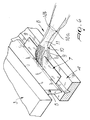
- the reference numeral 1 designates a safety device particularly for industrial machines, such as for example a bending press 2 of the type with slow descent, shown in Figure 1.
- the bending press 2 comprises a supporting frame 3 for a first fixed part, such as a die, designated by the reference numeral 4.
- the die 4 is usually arranged approximately horizontally and its upper surface is conveniently shaped according to a preset geometry that depends on the blank to be machined or in any case on the operation to be performed.
- a tool 5 that constitutes a movable part, such as for example a blade or a punch, that is slidingly associated with the frame 3 along a working axis that is advantageously perpendicular to the plane of arrangement of the die 4.
- Actuation means included in the machine 2, for controlling the movement of the tool 5 are provided.
- An operator 6 can interpose manually, between the die 4 and the tool 5, a blank such as for example a metal plate 7.
- the metal plate 7 undergoes deformation and in particular is bent along the line formed by the shape and position of said tool.
- the safety device 1 comprises a glove 8 that can be worn by the operator 6 and is provided with first electrically conducting regions, generally designated by the reference numeral 9, that are arranged approximately at the back of the glove 8.
- the glove 8 has no conducting regions at its palm.
- Figures 2 to 4 illustrate some possible embodiments of the glove 8, in each of which the first conducting regions 9 are constituted by a strip 10 that is conveniently shaped to form a winding path so as to affect or extend over approximately the entire region of the back of the glove 8.
- Such first conducting regions 9 are therefore differentiated from second nonconducting regions 11 of the back of the glove 8, which are made of a material that is not electrically conductive.
- first conducting regions 9 on the glove 8 can be achieved for example by interconnecting thereto the strip 10, which is made of an electrically conducting material, such as a metallic material or a particular conducting plastic material.
- the strip 10 can be associated with the back of the glove 8, which does not conduct, for example by sewing, gluing, thermal bonding or by way of a molding operation.
- connection of the first conducting regions 9 must not modify substantially the mechanical characteristics of the glove 8, particularly finger flexing.
- the strip 10 has two ends, designated by the reference numerals 12a and 12b, that are arranged approximately in the wrist region.
- One or more first cables can be connected detachably to the ends 12a and 12b and can be coupled temporarily to the item of clothing of the operator 6 in order to constitute a transmitting means that transmit a signal, preferably an electric signal, between the bending press 2 and a control unit CU and controls the stopping of the descent of the tool 5.
- a transmitting means that transmit a signal, preferably an electric signal, between the bending press 2 and a control unit CU and controls the stopping of the descent of the tool 5.
- control unit CU is suitable to control for example any flow of electrical current in a first circuit that is normally open and therefore without current and comprises the bending press 2, the first conducting regions 9 of the glove 8, the cable 13 and any means for transmitting the electrical signal that can be interposed between the cable 13 and the control unit.
- the first cable 13 transmits the signal to a mat 14, which is made of conducting material and is in turn electrically connected by means of a second cable 15 to the control unit, which is advantageously accommodated and connected to the bending press 2.
- the first circuit closes and therefore the descent of the tool 5 is halted.
- the shape of the glove 8 advantageously entails the provision of a single strip 10 of conducting material, since the control unit monitors the flow of current within a second circuit that comprises indeed the strip 10.
- the control unit detects an interruption or a considerable reduction in the current in the second circuit, accordingly stopping the press 2 or indicating in various manners to the operator or to the department manager the possible failure of the safety device 1.
- Such safety device 1 can be used alone but it can be preferably associated with a separate safety device of a known type, such as the photocell safety device described above, that intervenes whenever it is necessary to deactivate said device.
- Such control unit checks the correct functionality of the glove by detecting the current in the second circuit and indicates, in case of failure, the need to replace the glove being used with a new one.
- the operator can work normally at the bending press 2, touching the die 4 and the blank 7, since the palm of the glove is nonconducting and therefore does not close the first circuit.
- the safety device in fact halts the industrial machine immediately, as soon as contact occurs between the conducting regions of the glove and the descending tool, accordingly allowing the operator to work in absolute confidence.
- Said safety device further allows to improve the operating speed, with a consequent increase in the efficiency of the industrial machine.
- the first circuit comprises wireless transmission means for transmission of the signal, for example by means of radio frequencies, ultrasound or infrared beams, so that each operator wears a transmitter that is electrically connected to the glove and communicates with the control unit.
- the second circuit for detecting correct functionality of the glove might optionally be omitted, or might not be connected to the control unit.
- a second circuit that is completely accommodated within the glove and comprises a sensor constituting indication means for detecting the flow of current and for providing an indication if the circuit is open.
- the invention may of course also be applied to other industrial machines, preferably slow-moving ones, such as for example bending presses provided with an upper fixed punch and with a lower movable die that can be moved so as to abut against the punch.
- slow-moving ones such as for example bending presses provided with an upper fixed punch and with a lower movable die that can be moved so as to abut against the punch.
Landscapes
- Engineering & Computer Science (AREA)
- Textile Engineering (AREA)
- General Engineering & Computer Science (AREA)
- Mechanical Engineering (AREA)
- Bending Of Plates, Rods, And Pipes (AREA)
- Presses And Accessory Devices Thereof (AREA)
- Gloves (AREA)
Abstract
Description
Claims (17)
- A safety device particularly for industrial machines such as for example bending presses (12), provided with at least one first part (5) that can move in abutment toward a second fixed part (4), at least one blank (7) being interposable between said first and second parts (5, 4), characterized in that it comprises at least one glove (8) that can be worn by the operator (6) and is provided with first electrically conducting regions (9) and with second nonconducting regions (11), said glove (8) constituting, in case of contact with said industrial machine and/or with said blank (7), a means for transmitting an electrical signal between said industrial machine and a control unit in order to stop the descent of said first movable part (5).
- A safety device particularly for industrial machines such as bending presses provided with an upper tool (5) driven into abutment toward a lower die (4), at least one blank (7) being interposable between said die (4) and said tool (5), characterized in that it comprises at least one glove (8) that can be worn by the operator (6), is provided with first electrically conducting regions (9) that are located at the back of the glove (8) and has no conducting regions at the palm, said glove (8) constituting, in case of contact with said industrial machine (2) and/or with said blank (7), a means (13) for transmitting an electrical signal between said industrial machine (2) and a control unit in order to block the descent of said tool (5).
- The safety device according to claims 1 or 2, characterized in that it comprises a first circuit (13, 14, 15), between said at least one glove (8), said control unit (CU) and said industrial machine, which can be closed electrically upon contact of said first conducting regions (9) with said tool (5).
- The safety device according to claim 3, characterized in that said first conducting regions (9) of said at least one glove (8) comprise a strip (10) of electrically conducting material that affects at least the finger region of the back of said glove.
- The safety device according to claims 3 and 4, characterized in that said strip (10) is contoured along an open and winding path, so as to affect preferably all the regions of the back of said glove (8).
- The safety device according to claims 3 and 4, characterized in that said strip (10) forms on the back of said at least one glove (8) second electrically non-conducting regions (11) that are connected to the palm of said glove (8).
- The safety device according to one or more of the preceding claims, characterized in that said first conducting regions (9) of said at least one glove (8) are obtained by connecting said strip (10) thereto, said strip (10) being made of electrically conducting material, such as a metallic material or a particular conducting plastic material.
- The safety device according to claims 3 and 7, characterized in that said strip (10) is associated with the back of said at least one nonconducting glove (8) by sewing or gluing.
- The safety device according to claims 3 and 7, characterized in that said strip (10) is associated with the back of said at least one nonconducting glove (8) by thermal bonding or by molding.
- The safety device according to claims 3 and 7, characterized in that said at least one glove (8), comprising a back with first conducting regions (9) and second nonconducting regions (11) and a nonconducting palm, is provided by way of single molding.
- The safety device according to one or more of the preceding claims, characterized in that said first conducting regions (9) are provided by depositing electrically conducting paints onto the back of said at least one glove (8).
- The safety device according to one or more of the preceding claims, characterized in that said first conducting regions (9) can be connected electrically, by way of one or more first cables (13, 15), to a control unit (CU) that in turn is connected to said industrial machine (2) so as to form said first circuit (13, 14, 15) between said tool (5) and said glove (8).
- The safety device according to claims 3 and 12, characterized in that when said first circuit (13, 14, 15) closes, the control unit stops the descent of said tool (5) and optionally deactivates said industrial machine (2).
- The safety device according to one or more of the preceding claims, characterized in that it comprises at least one second electric circuit (10) for applying and controlling a separate control current that circulates in said first conducting regions (9).
- The safety device according to claims 3 and 14, characterized in that partial damage of said first conducting regions (9) with breakage of said strip (10) in one or more points forces the activation of indication means for indicating the malfunction of said glove (8).
- The safety device according to claims 3 and 15, characterized in that said indication means are accommodated in said control unit (CU), which is part of said second circuit, so as to allow the optional stopping of said industrial machine upon detection of a fault in said at least one glove (8).
- The safety device according to one or more of the preceding claims, characterized in that it comprises wireless transmission means for transmission of the signal between said glove (8) and said tool (5), constituted by a transmitter that is electrically connected to said at least one glove (8) and communicates with said control unit (CU).
Applications Claiming Priority (3)
| Application Number | Priority Date | Filing Date | Title |
|---|---|---|---|
| ITTV20030018 | 2003-02-07 | ||
| ITTV20030018 ITTV20030018A1 (en) | 2003-02-07 | 2003-02-07 | SAFETY DEVICE, ESPECIALLY FOR INDUSTRIAL MACHINES SUCH AS BENDING PRESSES. |
| CA2457597A CA2457597C (en) | 2003-02-07 | 2004-02-12 | Safety device for industrial machines |
Publications (3)
| Publication Number | Publication Date |
|---|---|
| EP1445531A2 true EP1445531A2 (en) | 2004-08-11 |
| EP1445531A3 EP1445531A3 (en) | 2005-04-06 |
| EP1445531B1 EP1445531B1 (en) | 2010-10-20 |
Family
ID=32991678
Family Applications (1)
| Application Number | Title | Priority Date | Filing Date |
|---|---|---|---|
| EP04002216A Expired - Lifetime EP1445531B1 (en) | 2003-02-07 | 2004-02-02 | Safety device, particularly for industrial machines, such as bending presses |
Country Status (3)
| Country | Link |
|---|---|
| US (1) | US7124872B2 (en) |
| EP (1) | EP1445531B1 (en) |
| CA (1) | CA2457597C (en) |
Cited By (5)
| Publication number | Priority date | Publication date | Assignee | Title |
|---|---|---|---|---|
| CN101722253B (en) * | 2008-10-31 | 2011-12-21 | 马永涛 | Safety protection device of rigid punching machine |
| WO2012007604A1 (en) * | 2010-07-01 | 2012-01-19 | Martinez Sanchez Jose Maria | Device for preventing occupational accidents |
| EP3096066A1 (en) | 2015-03-23 | 2016-11-23 | Trumpf Maschinen Austria GmbH & CO. KG. | Machine control element with security functionality |
| WO2020178748A1 (en) * | 2019-03-05 | 2020-09-10 | Grasselli S.P.A. | Improved garment |
| IT201900007194A1 (en) | 2019-05-24 | 2020-11-24 | Antis Group S P A | WEARABLE PERSONAL PROTECTIVE EQUIPMENT AND SYSTEM FOR MANAGING WEARABLE PERSONAL PROTECTIVE EQUIPMENT. |
Families Citing this family (7)
| Publication number | Priority date | Publication date | Assignee | Title |
|---|---|---|---|---|
| US7236849B2 (en) * | 2004-02-23 | 2007-06-26 | Walsh Matthew J | Safety system for power equipment |
| US7719422B1 (en) * | 2006-08-30 | 2010-05-18 | Jay Steinmetz | Wireless internet protocol-based action-oriented system for remote wireless alerting and action |
| US20100271208A1 (en) * | 2007-08-30 | 2010-10-28 | Jay Steinmetz | Wireless Network-Based Action-Oriented System For Remote Wireless Alerting And Action |
| US20090242539A1 (en) * | 2008-04-01 | 2009-10-01 | Wassel Damian A | Heating System |
| EP2586314B1 (en) * | 2011-10-25 | 2017-01-18 | Albert Handtmann Maschinenfabrik GmbH & Co. KG | Food machine, in particular machine for processing and producing sausage and method for operating same |
| CN107900206A (en) * | 2017-11-29 | 2018-04-13 | 无锡市汇鼎金属制管有限公司 | A kind of metal tube processing flatting apparatus |
| US10837599B2 (en) * | 2018-02-08 | 2020-11-17 | Alken Inc. | Safety system for machinery |
Citations (3)
| Publication number | Priority date | Publication date | Assignee | Title |
|---|---|---|---|---|
| FR2712837A1 (en) | 1993-11-22 | 1995-06-02 | Delmas Daniel | Protective system for user of powered cutting tools |
| US5669809A (en) | 1996-05-22 | 1997-09-23 | Townsend; Ray T. | Safety means for powered machinery |
| WO2003027565A1 (en) | 2001-09-27 | 2003-04-03 | Rapid Repairs Bvba | Safety arrangements for power machinery |
Family Cites Families (4)
| Publication number | Priority date | Publication date | Assignee | Title |
|---|---|---|---|---|
| US3953770A (en) * | 1974-07-11 | 1976-04-27 | Jinnosuke Hayashi | Safety equipment for machinery used in processing plates, etc. |
| US5201684A (en) * | 1989-10-10 | 1993-04-13 | Townsend Engineering Company | Safety means for powered machinery |
| US5083973A (en) * | 1989-10-26 | 1992-01-28 | Townsend Engineering Company | Safety method and means for stopping meat skinning machines |
| AT412071B (en) * | 2001-08-17 | 2004-09-27 | Trumpf Maschinen Austria Gmbh | PRODUCTION DEVICE, IN PARTICULAR BENDING PRESS, AND METHOD FOR OPERATING A PRODUCTION DEVICE |
-
2004
- 2004-02-02 EP EP04002216A patent/EP1445531B1/en not_active Expired - Lifetime
- 2004-02-02 US US10/768,055 patent/US7124872B2/en not_active Expired - Fee Related
- 2004-02-12 CA CA2457597A patent/CA2457597C/en not_active Expired - Fee Related
Patent Citations (3)
| Publication number | Priority date | Publication date | Assignee | Title |
|---|---|---|---|---|
| FR2712837A1 (en) | 1993-11-22 | 1995-06-02 | Delmas Daniel | Protective system for user of powered cutting tools |
| US5669809A (en) | 1996-05-22 | 1997-09-23 | Townsend; Ray T. | Safety means for powered machinery |
| WO2003027565A1 (en) | 2001-09-27 | 2003-04-03 | Rapid Repairs Bvba | Safety arrangements for power machinery |
Cited By (5)
| Publication number | Priority date | Publication date | Assignee | Title |
|---|---|---|---|---|
| CN101722253B (en) * | 2008-10-31 | 2011-12-21 | 马永涛 | Safety protection device of rigid punching machine |
| WO2012007604A1 (en) * | 2010-07-01 | 2012-01-19 | Martinez Sanchez Jose Maria | Device for preventing occupational accidents |
| EP3096066A1 (en) | 2015-03-23 | 2016-11-23 | Trumpf Maschinen Austria GmbH & CO. KG. | Machine control element with security functionality |
| WO2020178748A1 (en) * | 2019-03-05 | 2020-09-10 | Grasselli S.P.A. | Improved garment |
| IT201900007194A1 (en) | 2019-05-24 | 2020-11-24 | Antis Group S P A | WEARABLE PERSONAL PROTECTIVE EQUIPMENT AND SYSTEM FOR MANAGING WEARABLE PERSONAL PROTECTIVE EQUIPMENT. |
Also Published As
| Publication number | Publication date |
|---|---|
| CA2457597C (en) | 2011-11-08 |
| CA2457597A1 (en) | 2004-06-17 |
| US20040155533A1 (en) | 2004-08-12 |
| EP1445531A3 (en) | 2005-04-06 |
| US7124872B2 (en) | 2006-10-24 |
| EP1445531B1 (en) | 2010-10-20 |
Similar Documents
| Publication | Publication Date | Title |
|---|---|---|
| US7124872B2 (en) | Safety device for industrial machines | |
| US3861016A (en) | Electric safety control mechanism | |
| US7448242B2 (en) | Method for securing a machine tool and opto-electronic sensor for carrying out such a method | |
| US7281403B2 (en) | Production device, in particular a folding press and a method for operating a production device | |
| CA1186791A (en) | Safety switch system for industrial machines | |
| JP4839068B2 (en) | Safety device and method for determining overtravel in a machine | |
| US1684296A (en) | Peessing oe punching machine | |
| US5199338A (en) | Automatic workholder avoidance system for a press | |
| AU4771697A (en) | Safety device on metal-forming machine tools | |
| CN207026364U (en) | Punching machine mechanical arm grabbing workpiece protection device | |
| KR102123847B1 (en) | Machine safety system | |
| CN2785751Y (en) | Combined die of punching unit | |
| CN208555775U (en) | A kind of safety guard of lathe | |
| KR100419589B1 (en) | Protection device of Press | |
| KR100430072B1 (en) | A Safety Mat with Multiple Switchs | |
| CN114536408B (en) | Belt breakage protection system of robot | |
| US969961A (en) | Protecting mechanism for pressing, punching, and cutting machines, &c. | |
| EP3935305A1 (en) | Improved garment | |
| CN214263686U (en) | Foot frock is cut to IPM drive module for servo controller drive plate | |
| CN210308129U (en) | Automatic revise round knife initial position and cut bundle strip machine | |
| US3016006A (en) | Paper processing machines for processing workpieces in the form of sheets, plates or the like | |
| KR930008218Y1 (en) | Device for confirming an operation of press works | |
| CN113182390A (en) | Numerical control bending machine | |
| CN119184402A (en) | Button punching device | |
| CN121650075A (en) | A device and method for cutting battery cell tabs |
Legal Events
| Date | Code | Title | Description |
|---|---|---|---|
| PUAI | Public reference made under article 153(3) epc to a published international application that has entered the european phase |
Free format text: ORIGINAL CODE: 0009012 |
|
| AK | Designated contracting states |
Kind code of ref document: A2 Designated state(s): AT BE BG CH CY CZ DE DK EE ES FI FR GB GR HU IE IT LI LU MC NL PT RO SE SI SK TR |
|
| AX | Request for extension of the european patent |
Extension state: AL LT LV MK |
|
| PUAL | Search report despatched |
Free format text: ORIGINAL CODE: 0009013 |
|
| AK | Designated contracting states |
Kind code of ref document: A3 Designated state(s): AT BE BG CH CY CZ DE DK EE ES FI FR GB GR HU IE IT LI LU MC NL PT RO SE SI SK TR |
|
| AX | Request for extension of the european patent |
Extension state: AL LT LV MK |
|
| 17P | Request for examination filed |
Effective date: 20050801 |
|
| AKX | Designation fees paid |
Designated state(s): AT BE BG CH CY CZ DE DK EE ES FI FR GB GR HU IE IT LI LU MC NL PT RO SE SI SK TR |
|
| 17Q | First examination report despatched |
Effective date: 20070117 |
|
| GRAP | Despatch of communication of intention to grant a patent |
Free format text: ORIGINAL CODE: EPIDOSNIGR1 |
|
| GRAS | Grant fee paid |
Free format text: ORIGINAL CODE: EPIDOSNIGR3 |
|
| GRAA | (expected) grant |
Free format text: ORIGINAL CODE: 0009210 |
|
| AK | Designated contracting states |
Kind code of ref document: B1 Designated state(s): AT BE BG CH CY CZ DE DK EE ES FI FR GB GR HU IE IT LI LU MC NL PT RO SE SI SK TR |
|
| REG | Reference to a national code |
Ref country code: GB Ref legal event code: FG4D |
|
| REG | Reference to a national code |
Ref country code: CH Ref legal event code: EP |
|
| REG | Reference to a national code |
Ref country code: IE Ref legal event code: FG4D |
|
| REF | Corresponds to: |
Ref document number: 602004029627 Country of ref document: DE Date of ref document: 20101202 Kind code of ref document: P |
|
| REG | Reference to a national code |
Ref country code: NL Ref legal event code: VDEP Effective date: 20101020 |
|
| PG25 | Lapsed in a contracting state [announced via postgrant information from national office to epo] |
Ref country code: FI Free format text: LAPSE BECAUSE OF FAILURE TO SUBMIT A TRANSLATION OF THE DESCRIPTION OR TO PAY THE FEE WITHIN THE PRESCRIBED TIME-LIMIT Effective date: 20101020 Ref country code: BG Free format text: LAPSE BECAUSE OF FAILURE TO SUBMIT A TRANSLATION OF THE DESCRIPTION OR TO PAY THE FEE WITHIN THE PRESCRIBED TIME-LIMIT Effective date: 20110120 Ref country code: AT Free format text: LAPSE BECAUSE OF FAILURE TO SUBMIT A TRANSLATION OF THE DESCRIPTION OR TO PAY THE FEE WITHIN THE PRESCRIBED TIME-LIMIT Effective date: 20101020 Ref country code: PT Free format text: LAPSE BECAUSE OF FAILURE TO SUBMIT A TRANSLATION OF THE DESCRIPTION OR TO PAY THE FEE WITHIN THE PRESCRIBED TIME-LIMIT Effective date: 20110221 Ref country code: SI Free format text: LAPSE BECAUSE OF FAILURE TO SUBMIT A TRANSLATION OF THE DESCRIPTION OR TO PAY THE FEE WITHIN THE PRESCRIBED TIME-LIMIT Effective date: 20101020 Ref country code: SE Free format text: LAPSE BECAUSE OF FAILURE TO SUBMIT A TRANSLATION OF THE DESCRIPTION OR TO PAY THE FEE WITHIN THE PRESCRIBED TIME-LIMIT Effective date: 20101020 Ref country code: NL Free format text: LAPSE BECAUSE OF FAILURE TO SUBMIT A TRANSLATION OF THE DESCRIPTION OR TO PAY THE FEE WITHIN THE PRESCRIBED TIME-LIMIT Effective date: 20101020 |
|
| PG25 | Lapsed in a contracting state [announced via postgrant information from national office to epo] |
Ref country code: BE Free format text: LAPSE BECAUSE OF FAILURE TO SUBMIT A TRANSLATION OF THE DESCRIPTION OR TO PAY THE FEE WITHIN THE PRESCRIBED TIME-LIMIT Effective date: 20101020 Ref country code: GR Free format text: LAPSE BECAUSE OF FAILURE TO SUBMIT A TRANSLATION OF THE DESCRIPTION OR TO PAY THE FEE WITHIN THE PRESCRIBED TIME-LIMIT Effective date: 20110121 |
|
| PG25 | Lapsed in a contracting state [announced via postgrant information from national office to epo] |
Ref country code: CZ Free format text: LAPSE BECAUSE OF FAILURE TO SUBMIT A TRANSLATION OF THE DESCRIPTION OR TO PAY THE FEE WITHIN THE PRESCRIBED TIME-LIMIT Effective date: 20101020 Ref country code: EE Free format text: LAPSE BECAUSE OF FAILURE TO SUBMIT A TRANSLATION OF THE DESCRIPTION OR TO PAY THE FEE WITHIN THE PRESCRIBED TIME-LIMIT Effective date: 20101020 Ref country code: ES Free format text: LAPSE BECAUSE OF FAILURE TO SUBMIT A TRANSLATION OF THE DESCRIPTION OR TO PAY THE FEE WITHIN THE PRESCRIBED TIME-LIMIT Effective date: 20110131 |
|
| PLBE | No opposition filed within time limit |
Free format text: ORIGINAL CODE: 0009261 |
|
| STAA | Information on the status of an ep patent application or granted ep patent |
Free format text: STATUS: NO OPPOSITION FILED WITHIN TIME LIMIT |
|
| PG25 | Lapsed in a contracting state [announced via postgrant information from national office to epo] |
Ref country code: SK Free format text: LAPSE BECAUSE OF FAILURE TO SUBMIT A TRANSLATION OF THE DESCRIPTION OR TO PAY THE FEE WITHIN THE PRESCRIBED TIME-LIMIT Effective date: 20101020 Ref country code: RO Free format text: LAPSE BECAUSE OF FAILURE TO SUBMIT A TRANSLATION OF THE DESCRIPTION OR TO PAY THE FEE WITHIN THE PRESCRIBED TIME-LIMIT Effective date: 20101020 Ref country code: DK Free format text: LAPSE BECAUSE OF FAILURE TO SUBMIT A TRANSLATION OF THE DESCRIPTION OR TO PAY THE FEE WITHIN THE PRESCRIBED TIME-LIMIT Effective date: 20101020 |
|
| 26N | No opposition filed |
Effective date: 20110721 |
|
| PG25 | Lapsed in a contracting state [announced via postgrant information from national office to epo] |
Ref country code: MC Free format text: LAPSE BECAUSE OF NON-PAYMENT OF DUE FEES Effective date: 20110228 |
|
| REG | Reference to a national code |
Ref country code: CH Ref legal event code: PL |
|
| PG25 | Lapsed in a contracting state [announced via postgrant information from national office to epo] |
Ref country code: LI Free format text: LAPSE BECAUSE OF NON-PAYMENT OF DUE FEES Effective date: 20110228 Ref country code: CH Free format text: LAPSE BECAUSE OF NON-PAYMENT OF DUE FEES Effective date: 20110228 |
|
| REG | Reference to a national code |
Ref country code: DE Ref legal event code: R097 Ref document number: 602004029627 Country of ref document: DE Effective date: 20110721 |
|
| REG | Reference to a national code |
Ref country code: IE Ref legal event code: MM4A |
|
| PG25 | Lapsed in a contracting state [announced via postgrant information from national office to epo] |
Ref country code: IE Free format text: LAPSE BECAUSE OF NON-PAYMENT OF DUE FEES Effective date: 20110202 |
|
| PGFP | Annual fee paid to national office [announced via postgrant information from national office to epo] |
Ref country code: IT Payment date: 20120224 Year of fee payment: 9 |
|
| PGFP | Annual fee paid to national office [announced via postgrant information from national office to epo] |
Ref country code: GB Payment date: 20130118 Year of fee payment: 10 Ref country code: DE Payment date: 20130328 Year of fee payment: 10 Ref country code: FR Payment date: 20130219 Year of fee payment: 10 |
|
| PG25 | Lapsed in a contracting state [announced via postgrant information from national office to epo] |
Ref country code: CY Free format text: LAPSE BECAUSE OF FAILURE TO SUBMIT A TRANSLATION OF THE DESCRIPTION OR TO PAY THE FEE WITHIN THE PRESCRIBED TIME-LIMIT Effective date: 20101020 Ref country code: LU Free format text: LAPSE BECAUSE OF NON-PAYMENT OF DUE FEES Effective date: 20110202 |
|
| PG25 | Lapsed in a contracting state [announced via postgrant information from national office to epo] |
Ref country code: TR Free format text: LAPSE BECAUSE OF FAILURE TO SUBMIT A TRANSLATION OF THE DESCRIPTION OR TO PAY THE FEE WITHIN THE PRESCRIBED TIME-LIMIT Effective date: 20101020 |
|
| PG25 | Lapsed in a contracting state [announced via postgrant information from national office to epo] |
Ref country code: HU Free format text: LAPSE BECAUSE OF FAILURE TO SUBMIT A TRANSLATION OF THE DESCRIPTION OR TO PAY THE FEE WITHIN THE PRESCRIBED TIME-LIMIT Effective date: 20101020 |
|
| REG | Reference to a national code |
Ref country code: DE Ref legal event code: R119 Ref document number: 602004029627 Country of ref document: DE |
|
| GBPC | Gb: european patent ceased through non-payment of renewal fee |
Effective date: 20140202 |
|
| REG | Reference to a national code |
Ref country code: FR Ref legal event code: ST Effective date: 20141031 |
|
| REG | Reference to a national code |
Ref country code: DE Ref legal event code: R119 Ref document number: 602004029627 Country of ref document: DE Effective date: 20140902 |
|
| PG25 | Lapsed in a contracting state [announced via postgrant information from national office to epo] |
Ref country code: DE Free format text: LAPSE BECAUSE OF NON-PAYMENT OF DUE FEES Effective date: 20140902 Ref country code: GB Free format text: LAPSE BECAUSE OF NON-PAYMENT OF DUE FEES Effective date: 20140202 Ref country code: FR Free format text: LAPSE BECAUSE OF NON-PAYMENT OF DUE FEES Effective date: 20140228 |
|
| PG25 | Lapsed in a contracting state [announced via postgrant information from national office to epo] |
Ref country code: IT Free format text: LAPSE BECAUSE OF NON-PAYMENT OF DUE FEES Effective date: 20140202 |