EP1450659B1 - An einer wand anbringbare haltevorrichtung für flüssigproduktbehälter - Google Patents
An einer wand anbringbare haltevorrichtung für flüssigproduktbehälter Download PDFInfo
- Publication number
- EP1450659B1 EP1450659B1 EP02786314A EP02786314A EP1450659B1 EP 1450659 B1 EP1450659 B1 EP 1450659B1 EP 02786314 A EP02786314 A EP 02786314A EP 02786314 A EP02786314 A EP 02786314A EP 1450659 B1 EP1450659 B1 EP 1450659B1
- Authority
- EP
- European Patent Office
- Prior art keywords
- plate
- lever
- slot
- wall
- designed
- Prior art date
- Legal status (The legal status is an assumption and is not a legal conclusion. Google has not performed a legal analysis and makes no representation as to the accuracy of the status listed.)
- Expired - Lifetime
Links
Images


Classifications
-
- A—HUMAN NECESSITIES
- A47—FURNITURE; DOMESTIC ARTICLES OR APPLIANCES; COFFEE MILLS; SPICE MILLS; SUCTION CLEANERS IN GENERAL
- A47K—SANITARY EQUIPMENT; ACCESSORIES THEREFOR, e.g. TOILET ACCESSORIES
- A47K5/00—Holders or dispensers for soap, toothpaste or the like
- A47K5/06—Dispensers for soap
- A47K5/12—Dispensers for soap for liquid or pasty soap
- A47K5/1211—Dispensers for soap for liquid or pasty soap using pressure on soap, e.g. with piston
- A47K5/1215—Dispensers for soap for liquid or pasty soap using pressure on soap, e.g. with piston applied by a peristaltic action
Definitions
- the present invention relates to a holder for a container for liquid products.
- a device for a holder for a container for liquid products for application on a wall is known, which container may be made of various materials such as plastic, glass, paper, metal or the like and which may be in the nature of a bag or bottle with a preferably detachable closure means that is elongate, which includes a dosing member such as a pump arrangement that can be influenced externally transversely and manually by part of an actuating member such as a lever pivotably joumalled in the holder, the container with an elongate closure means being designed to rest against the container, the blank for the container consisting of a substantially rectangular plate with a longitudinal and a transverse extension, which plate in its longitudinal direction has a longitudinally-running through-slot with two parts arranged one on each side of the slot and which plate is shaped substantially as a U about an axis perpendicular to the slot, the plate part on one side of the slot being bent inwards so
- a dispenser according to the preamble of claim 1 is disclosed in SE 516 147 C2 .
- EP 0 433 905 A2 discloses to use flat plates in a dispenser to compress and empty a tubular part.
- the object of the present invention is to provide a device such that upon movement of the actuating member a predetermined amount of the liquid product is supplied. In accordance with the present invention this is achieved by said hose-like part being squeezed together along a predetermined length thereof so that said part is totally emptied of its contents. This is achieved by the actuating member cooperating with the outer surface of the inwardly bent part of the rectangular plate. Said outer surface cooperates with a part of the actuating member which is substantially parallel with said surface in inserted position. It is thus suitable for the actuating member in inserted position to have a part that is parallel with said outer surface.
- the quantity of product squeezed out will thus be determined by the length of the part of the actuating member that cooperates with said outer surface of the inwardly bent part. It is thus suitable for the inwardly bent part to have an entirely flat rectangular surface at its centre.
- the actuating member may also be provided with a plate cooperating with the surface just mentioned.
- the actuating member and/or the inwardly bent outer surface may be provided on the side closest to the container with means to throttle the hose before the squeezing effect occurs.
- the liquid product from the hose is thus prevented from returning to the container.
- the hose may be provided at its free end with a valve that is resilient and always assumes closed position but which, upon being influenced by pressure from the liquid product in the hose, opens and permits a certain quantity to be released.
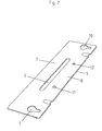
- FIGs 1 and 2 showing a known holder and material required for its manufacture.
- a rectangular plate is used initially, which is provided with a central opening 6 and two plate-shaped parts 7 and 8, one on each side of the slot. Holes 9 and 10 are also provided for attaching the bent plate.
- the plate illustrated in Figure 2 is bent in the manner shown in Figure 1 where the plate 5 is U-shaped. It is the part of the plate to the right of the slot 6 that forms the upper part 8 of the holder and the part to the left of the slot 6 that forms the inwardly bent wall 7 that is to constitute the contact wall against a tapping part of a container with liquid products.
- the bent unit has two attachment flanges 13 and 14 with holes 15 and 16 for attachment screws.
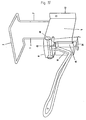
- FIG. 3 Another known device has been developed which deviates somewhat from the holder shown in Figure 1 in that the holder part 8 has been made considerably shorter and the actuator is arranged differently, having a longer, flat, straight part 18 that shall be brought more or less into contact with a tubular part 25 which also requires a support 24 for its free end.
- the most important feature of the holders illustrated in Figures 3 and 4 is that they are suitable for receptacles containing liquid products and having a long pipe such as the discharge pipe 25 which may include a pump or other means of discharging liquid.
- Figure 5 illustrates a device similar to that shown in Figure 4 but with a tubular casing, optional in shape, into which casing a box with contents as in Figure 4 can be inserted.
- the casing may have a smooth surface or it may consist of a number of parallel slats arranged one after the other, or of a mesh frame.
- a receptacle containing liquid products with a protective casing so that it cannot be interfered with.
- a double casing consisting of a flat part 31 with two side flanges 35 and 36 cooperating with a domed casing 30. This is provided at its lower end with journalling pins 26 running in closed slots 34, i.e.
- the journalling pins 26 are displaceable from one end of the slot to its other end. If the domed part 30 is flapped down towards the part 31 the studs 27 will engage in the grooves 32 and 33 which have openings. Thus, if the domed part 30 is flapped down towards the part 31 the studs 27 will cooperate with the grooves 32 and 33 and in closed position the domed part 30 can be moved to the lower end of the slot 34 and in this position the domed part 30 can be locked to the flat part 31 so that the receptacle with liquid products is inaccessible for damage. As can be seen in Figure 7 , to open the domed outer casing it must be moved upwards some distance until it can be folded out and assume a position perpendicular to the part 31. The reason for this upward movement is, when the domed casing is down, to protect the actual holder arrangement. It should be evident that the casing described in Figures 6 , 7 and 9 can very well be used for holders other than the one depicted in the description.
- the plate 37 has an outwardly bent part 38, as is also the case at the upper end of the flat surface of the inwardly bent part where a flange 39 or the like is arranged, whereupon the parts 38 and 39 throttle the hose 25 before the hose is compressed by the parts 37 and 40.
- the flat plate 5 (see Fig. 2 ) is also provided with a second groove 41 and, thanks to this, a protruding part 42 is obtained that can serve as support for the hose. It may be suitable to arrange a resilient valve at the end of the hose, this valve being designed to open and release the predetermined quantity of liquid product when liquid product from the hose subjects the valve to pressure.
- Figure 11 shows a second embodiment of the present invention differing from the previous embodiment in that the plate 37 has been replaced by a specially shaped part 18 of the lower part of the lever 17.
- the lower part 18 will function in exactly the same way as the part 38 of the plate 37.
- the inwardly bent part 7 has an inwardly curved flange 44 at its upper end, corresponding to the unit 39 in Figure 10 .
- a transverse part 43 attached on the specially shaped part 18 of the lever 17 cooperates with the above-mentioned unit.
- valve arrangement at the end of the hose may also be designed in various ways that offer the same function as that described.
Landscapes
- Health & Medical Sciences (AREA)
- Public Health (AREA)
- Containers And Packaging Bodies Having A Special Means To Remove Contents (AREA)
- Coating Apparatus (AREA)
- Filling Of Jars Or Cans And Processes For Cleaning And Sealing Jars (AREA)
- Manipulator (AREA)
- Devices For Use In Laboratory Experiments (AREA)
Claims (4)
- Halter und Spendervorrichtung für Behälter, die ein flüssiges Produkt enthalten und einen länglichen röhrenförmigen Auslassteil aufweisen,
wobei die Vorrichtung an einer Wand anbringbar ist und einen Rahmen (5) zum Halten eines Flüssigkeitsbehälters aufweist, und einen Hebel (17), der schwenkbar an dem Rahmen (5) um eine Horizontalachse angebracht ist und einen Betätigungsteil (18) mit einer geraden Form aufweist, der ausgestaltet ist, um durch Herunterschwenken des Hebels (16) gegen den länglichen Auslassteil (25) des Flüssigkeitsbehälters im Wesentlichen in Richtung auf die Wand zu drücken ist,
wobei der Rahmen aus einer rechteckigen Platte erhalten wurde, die einen länglichen Schlitz (6) aufweist, durch Biegen der Platte um Biegeachsen, die rechtwinklig zu dem Schlitz (6) sind, derart, dass zwei Flansche (13, 14) zum Anbringen an der Wand gebildet werden und dazwischen der Plattenteil oberhalb des Schlitzes nach außen in ein U-Form gebogen ist, deren konvexe Seite von der Wand weg zeigt,
wobei der zentrale Bereich des Plattenteils (7) unterhalb des Schlitzes (6) nach innen in eine U-Form gebogen ist, deren konkave Seite von der Wand weg weist und ausgebildet ist, um den röhrenförmigen Auslassteils des Flüssigkeitsbehälters aufzunehmen und um als Gegenfläche für den Betätigungsteil (18) des Hebels (17) zu dienen,
dadurch gekennzeichnet, dass dem Mittenteil des U-förmig nach innen gebogenen Plattenteils (7) mit einer flachen Fläche (40) versehen ist, die zum Zusammenwirken mit dem geraden Betätigungsteil (18) des Hebels (17) ausgebildet ist, wobei der Hebel (17) so ausgebildet ist, dass in der untersten Position des Hebels (17) sein geradförmiger Betätigungsteil und die flache Fläche (14) parallel zueinander sind, wobei der röhrenförmige Auslassteil der Flüssigkeitsbehälter vollständig dazwischen komprimiert ist. - Vorrichtung nach Anspruch 1, dadurch gekennzeichnet, dass der Betätigungsteil (18) des Hebels (17) mit einer flachen Einheit (37) wie einer Platte versehen ist.
- Vorrichtung nach Anspruch 1 oder 2, dadurch gekennzeichnet, dass eine oder beide flache Flächen (40) der Platte (37) mit Drosselmitteln (38, 39) versehen ist, die zur Ermöglichung einer Drosselung vor der Kompression ausgebildet sind.
- Vorrichtung nach einem der Ansprüche 1 bis 3, dadurch gekennzeichnet, dass die Platte, aus der der Rahmen (5) durch Biegen erhalten wird, einen zweiten Schlitz (41) aufweist, und der Plattenteil unterhalb des zweiten Schlitzes nach außen in eine U-Form gebogen ist, so dass der nach innen gebogene Teil (7) zwischen zwei nach außen gebogenen Teilen (8, 42) ist.
Applications Claiming Priority (3)
| Application Number | Priority Date | Filing Date | Title |
|---|---|---|---|
| SE0103748A SE0103748L (sv) | 2001-11-13 | 2001-11-13 | Anordning vid hållare för applicering på en vägg för behållare för flytande produkter |
| SE0103748 | 2001-11-13 | ||
| PCT/SE2002/002051 WO2003059137A1 (en) | 2001-11-13 | 2002-11-12 | Device for holder for container for liquid products for application on a wall |
Publications (2)
| Publication Number | Publication Date |
|---|---|
| EP1450659A1 EP1450659A1 (de) | 2004-09-01 |
| EP1450659B1 true EP1450659B1 (de) | 2010-09-08 |
Family
ID=20285940
Family Applications (1)
| Application Number | Title | Priority Date | Filing Date |
|---|---|---|---|
| EP02786314A Expired - Lifetime EP1450659B1 (de) | 2001-11-13 | 2002-11-12 | An einer wand anbringbare haltevorrichtung für flüssigproduktbehälter |
Country Status (9)
| Country | Link |
|---|---|
| US (1) | US7083154B2 (de) |
| EP (1) | EP1450659B1 (de) |
| JP (1) | JP2005514282A (de) |
| CN (1) | CN1585614B (de) |
| AT (1) | ATE480173T1 (de) |
| AU (1) | AU2002354299A1 (de) |
| DE (1) | DE60237633D1 (de) |
| SE (1) | SE0103748L (de) |
| WO (1) | WO2003059137A1 (de) |
Families Citing this family (2)
| Publication number | Priority date | Publication date | Assignee | Title |
|---|---|---|---|---|
| FR2928255B1 (fr) * | 2008-03-05 | 2013-06-28 | Prodene Klint Soc Lab | "distributeur de produit fluide et support d'un tel distributeur" |
| FR2992457B1 (fr) * | 2012-06-21 | 2014-08-08 | Cap | Dispositif de support publicitaire |
Family Cites Families (7)
| Publication number | Priority date | Publication date | Assignee | Title |
|---|---|---|---|---|
| US4164306A (en) * | 1978-04-03 | 1979-08-14 | Towlsaver, Inc. | Soap dispenser including removable soap supply container positioner and stabilizer |
| SE463902B (sv) | 1988-04-15 | 1991-02-11 | Harry Holm | Haallare till en behaallare foer flytande produkter |
| US4930667A (en) | 1989-01-23 | 1990-06-05 | Steiner Company, Inc. | Breathing device for soap dispenser |
| EP0433905B1 (de) | 1989-12-22 | 1993-08-11 | Basotherm GmbH | Vorrichtung zur Abgabe fliessfähiger Medien |
| US5207355A (en) * | 1991-12-30 | 1993-05-04 | Thomsen Peter N | High viscosity pump system for dispenser pouch |
| SE516147C2 (sv) | 1999-06-03 | 2001-11-26 | Holms Trading Ab | Anordning vid hållare för applicering på en vägg för behållare för flytande produkter |
| CN2432166Y (zh) * | 2000-05-10 | 2001-05-30 | 宗贻平 | 手动取液器 |
-
2001
- 2001-11-13 SE SE0103748A patent/SE0103748L/ not_active Application Discontinuation
-
2002
- 2002-11-12 CN CN02822580.5A patent/CN1585614B/zh not_active Expired - Fee Related
- 2002-11-12 EP EP02786314A patent/EP1450659B1/de not_active Expired - Lifetime
- 2002-11-12 AU AU2002354299A patent/AU2002354299A1/en not_active Abandoned
- 2002-11-12 DE DE60237633T patent/DE60237633D1/de not_active Expired - Lifetime
- 2002-11-12 WO PCT/SE2002/002051 patent/WO2003059137A1/en not_active Ceased
- 2002-11-12 AT AT02786314T patent/ATE480173T1/de not_active IP Right Cessation
- 2002-11-12 JP JP2003559308A patent/JP2005514282A/ja active Pending
- 2002-11-12 US US10/494,361 patent/US7083154B2/en not_active Expired - Fee Related
Also Published As
| Publication number | Publication date |
|---|---|
| ATE480173T1 (de) | 2010-09-15 |
| WO2003059137A1 (en) | 2003-07-24 |
| JP2005514282A (ja) | 2005-05-19 |
| CN1585614B (zh) | 2010-09-01 |
| SE0103748D0 (sv) | 2001-11-13 |
| DE60237633D1 (de) | 2010-10-21 |
| EP1450659A1 (de) | 2004-09-01 |
| US20050029422A1 (en) | 2005-02-10 |
| SE0103748L (sv) | 2003-05-14 |
| CN1585614A (zh) | 2005-02-23 |
| AU2002354299A1 (en) | 2003-07-30 |
| US7083154B2 (en) | 2006-08-01 |
Similar Documents
| Publication | Publication Date | Title |
|---|---|---|
| EP2225988B1 (de) | Spendergehäuse | |
| JP4338871B2 (ja) | 液体用壁掛けディスペンサー | |
| US4256242A (en) | Dispenser having a roller for squeezing amounts from a tube | |
| US4349133A (en) | Dispenser and refill package | |
| US4258865A (en) | Dispenser for liquid or pasty substances such as liquid soap and the like | |
| US5248066A (en) | Liquid dispenser with collapsible reservoir holder | |
| US5322194A (en) | Dispenser for collapsible tubes | |
| MXPA01002541A (es) | Grifo para despachar fluido. | |
| DK167305B1 (da) | Holder for beholdere til flydende produkter | |
| EP1450659B1 (de) | An einer wand anbringbare haltevorrichtung für flüssigproduktbehälter | |
| US12207771B2 (en) | Adaptor assembly for a fluid dispensing system | |
| NL1013344C2 (nl) | Afgeefsamenstel voor vloeistoffen. | |
| EP0635223A2 (de) | Spender für ein Zähflüssiges Produkt, der durch manuelle Druckausübung an seinem unteren Ende betätigt wird, insbesondere für kosmetische oder pharmazeutische Anwendung | |
| US4213543A (en) | Dispenser for dispensing the contents of collapsible packages | |
| EP1242291B1 (de) | Vorrichtung und verpackung zum abgeben von abgemessenen mengen eines pastösen materials | |
| JP3744547B2 (ja) | 液体石鹸などのための用量吐出ディスペンサ | |
| US20060071020A1 (en) | Product dispenser | |
| EP0275836B1 (de) | Portionsspender für flüssige Seife | |
| EP1180959B1 (de) | Halter für flüssigkeitsbehälter | |
| US6877640B1 (en) | Device for dispensing liquid or powder to washing machine and the like | |
| EP0577907A1 (de) | Selbstdichtender Verschluss für einen flexiblen Behälter | |
| NL1004869C1 (nl) | Houder voor een tube-verpakking. | |
| CA2526363C (en) | Wall-mounted dispenser for liquids | |
| MXPA99008905A (es) | Sistema de empaque y desecho | |
| HK1142507B (en) | Dispenser housing |
Legal Events
| Date | Code | Title | Description |
|---|---|---|---|
| PUAI | Public reference made under article 153(3) epc to a published international application that has entered the european phase |
Free format text: ORIGINAL CODE: 0009012 |
|
| 17P | Request for examination filed |
Effective date: 20040604 |
|
| AK | Designated contracting states |
Kind code of ref document: A1 Designated state(s): AT BE BG CH CY CZ DE DK EE ES FI FR GB GR IE IT LI LU MC NL PT SE SK TR |
|
| AX | Request for extension of the european patent |
Extension state: AL LT LV MK RO SI |
|
| 17Q | First examination report despatched |
Effective date: 20081208 |
|
| GRAP | Despatch of communication of intention to grant a patent |
Free format text: ORIGINAL CODE: EPIDOSNIGR1 |
|
| GRAS | Grant fee paid |
Free format text: ORIGINAL CODE: EPIDOSNIGR3 |
|
| GRAA | (expected) grant |
Free format text: ORIGINAL CODE: 0009210 |
|
| AK | Designated contracting states |
Kind code of ref document: B1 Designated state(s): AT BE BG CH CY CZ DE DK EE ES FI FR GB GR IE IT LI LU MC NL PT SE SK TR |
|
| REG | Reference to a national code |
Ref country code: GB Ref legal event code: FG4D |
|
| REG | Reference to a national code |
Ref country code: CH Ref legal event code: EP |
|
| REG | Reference to a national code |
Ref country code: IE Ref legal event code: FG4D |
|
| REF | Corresponds to: |
Ref document number: 60237633 Country of ref document: DE Date of ref document: 20101021 Kind code of ref document: P |
|
| REG | Reference to a national code |
Ref country code: NL Ref legal event code: VDEP Effective date: 20100908 |
|
| PG25 | Lapsed in a contracting state [announced via postgrant information from national office to epo] |
Ref country code: FI Free format text: LAPSE BECAUSE OF FAILURE TO SUBMIT A TRANSLATION OF THE DESCRIPTION OR TO PAY THE FEE WITHIN THE PRESCRIBED TIME-LIMIT Effective date: 20100908 Ref country code: AT Free format text: LAPSE BECAUSE OF FAILURE TO SUBMIT A TRANSLATION OF THE DESCRIPTION OR TO PAY THE FEE WITHIN THE PRESCRIBED TIME-LIMIT Effective date: 20100908 |
|
| PG25 | Lapsed in a contracting state [announced via postgrant information from national office to epo] |
Ref country code: CY Free format text: LAPSE BECAUSE OF FAILURE TO SUBMIT A TRANSLATION OF THE DESCRIPTION OR TO PAY THE FEE WITHIN THE PRESCRIBED TIME-LIMIT Effective date: 20100908 |
|
| PG25 | Lapsed in a contracting state [announced via postgrant information from national office to epo] |
Ref country code: SE Free format text: LAPSE BECAUSE OF FAILURE TO SUBMIT A TRANSLATION OF THE DESCRIPTION OR TO PAY THE FEE WITHIN THE PRESCRIBED TIME-LIMIT Effective date: 20100908 Ref country code: NL Free format text: LAPSE BECAUSE OF FAILURE TO SUBMIT A TRANSLATION OF THE DESCRIPTION OR TO PAY THE FEE WITHIN THE PRESCRIBED TIME-LIMIT Effective date: 20100908 Ref country code: GR Free format text: LAPSE BECAUSE OF FAILURE TO SUBMIT A TRANSLATION OF THE DESCRIPTION OR TO PAY THE FEE WITHIN THE PRESCRIBED TIME-LIMIT Effective date: 20101209 |
|
| PG25 | Lapsed in a contracting state [announced via postgrant information from national office to epo] |
Ref country code: EE Free format text: LAPSE BECAUSE OF FAILURE TO SUBMIT A TRANSLATION OF THE DESCRIPTION OR TO PAY THE FEE WITHIN THE PRESCRIBED TIME-LIMIT Effective date: 20100908 Ref country code: PT Free format text: LAPSE BECAUSE OF FAILURE TO SUBMIT A TRANSLATION OF THE DESCRIPTION OR TO PAY THE FEE WITHIN THE PRESCRIBED TIME-LIMIT Effective date: 20110110 Ref country code: CZ Free format text: LAPSE BECAUSE OF FAILURE TO SUBMIT A TRANSLATION OF THE DESCRIPTION OR TO PAY THE FEE WITHIN THE PRESCRIBED TIME-LIMIT Effective date: 20100908 Ref country code: IT Free format text: LAPSE BECAUSE OF FAILURE TO SUBMIT A TRANSLATION OF THE DESCRIPTION OR TO PAY THE FEE WITHIN THE PRESCRIBED TIME-LIMIT Effective date: 20100908 Ref country code: SK Free format text: LAPSE BECAUSE OF FAILURE TO SUBMIT A TRANSLATION OF THE DESCRIPTION OR TO PAY THE FEE WITHIN THE PRESCRIBED TIME-LIMIT Effective date: 20100908 |
|
| PG25 | Lapsed in a contracting state [announced via postgrant information from national office to epo] |
Ref country code: BE Free format text: LAPSE BECAUSE OF FAILURE TO SUBMIT A TRANSLATION OF THE DESCRIPTION OR TO PAY THE FEE WITHIN THE PRESCRIBED TIME-LIMIT Effective date: 20100908 Ref country code: ES Free format text: LAPSE BECAUSE OF FAILURE TO SUBMIT A TRANSLATION OF THE DESCRIPTION OR TO PAY THE FEE WITHIN THE PRESCRIBED TIME-LIMIT Effective date: 20101219 Ref country code: MC Free format text: LAPSE BECAUSE OF NON-PAYMENT OF DUE FEES Effective date: 20101130 |
|
| REG | Reference to a national code |
Ref country code: CH Ref legal event code: PL |
|
| PLBE | No opposition filed within time limit |
Free format text: ORIGINAL CODE: 0009261 |
|
| STAA | Information on the status of an ep patent application or granted ep patent |
Free format text: STATUS: NO OPPOSITION FILED WITHIN TIME LIMIT |
|
| PG25 | Lapsed in a contracting state [announced via postgrant information from national office to epo] |
Ref country code: CH Free format text: LAPSE BECAUSE OF NON-PAYMENT OF DUE FEES Effective date: 20101130 Ref country code: LI Free format text: LAPSE BECAUSE OF NON-PAYMENT OF DUE FEES Effective date: 20101130 |
|
| PGFP | Annual fee paid to national office [announced via postgrant information from national office to epo] |
Ref country code: FR Payment date: 20110408 Year of fee payment: 9 Ref country code: DE Payment date: 20110325 Year of fee payment: 9 |
|
| 26N | No opposition filed |
Effective date: 20110609 |
|
| GBPC | Gb: european patent ceased through non-payment of renewal fee |
Effective date: 20101208 |
|
| PG25 | Lapsed in a contracting state [announced via postgrant information from national office to epo] |
Ref country code: DK Free format text: LAPSE BECAUSE OF FAILURE TO SUBMIT A TRANSLATION OF THE DESCRIPTION OR TO PAY THE FEE WITHIN THE PRESCRIBED TIME-LIMIT Effective date: 20100908 |
|
| REG | Reference to a national code |
Ref country code: DE Ref legal event code: R097 Ref document number: 60237633 Country of ref document: DE Effective date: 20110609 |
|
| PG25 | Lapsed in a contracting state [announced via postgrant information from national office to epo] |
Ref country code: IE Free format text: LAPSE BECAUSE OF NON-PAYMENT OF DUE FEES Effective date: 20101112 |
|
| PG25 | Lapsed in a contracting state [announced via postgrant information from national office to epo] |
Ref country code: GB Free format text: LAPSE BECAUSE OF NON-PAYMENT OF DUE FEES Effective date: 20101208 |
|
| REG | Reference to a national code |
Ref country code: FR Ref legal event code: ST Effective date: 20120731 |
|
| REG | Reference to a national code |
Ref country code: DE Ref legal event code: R119 Ref document number: 60237633 Country of ref document: DE Effective date: 20120601 |
|
| PG25 | Lapsed in a contracting state [announced via postgrant information from national office to epo] |
Ref country code: LU Free format text: LAPSE BECAUSE OF NON-PAYMENT OF DUE FEES Effective date: 20101112 Ref country code: BG Free format text: LAPSE BECAUSE OF FAILURE TO SUBMIT A TRANSLATION OF THE DESCRIPTION OR TO PAY THE FEE WITHIN THE PRESCRIBED TIME-LIMIT Effective date: 20100908 |
|
| PG25 | Lapsed in a contracting state [announced via postgrant information from national office to epo] |
Ref country code: TR Free format text: LAPSE BECAUSE OF FAILURE TO SUBMIT A TRANSLATION OF THE DESCRIPTION OR TO PAY THE FEE WITHIN THE PRESCRIBED TIME-LIMIT Effective date: 20100908 |
|
| PG25 | Lapsed in a contracting state [announced via postgrant information from national office to epo] |
Ref country code: FR Free format text: LAPSE BECAUSE OF NON-PAYMENT OF DUE FEES Effective date: 20111130 |
|
| PG25 | Lapsed in a contracting state [announced via postgrant information from national office to epo] |
Ref country code: DE Free format text: LAPSE BECAUSE OF NON-PAYMENT OF DUE FEES Effective date: 20120601 |
|
| PG25 | Lapsed in a contracting state [announced via postgrant information from national office to epo] |
Ref country code: BG Free format text: LAPSE BECAUSE OF FAILURE TO SUBMIT A TRANSLATION OF THE DESCRIPTION OR TO PAY THE FEE WITHIN THE PRESCRIBED TIME-LIMIT Effective date: 20101208 |