EP1452458B1 - Food carton - Google Patents
Food carton Download PDFInfo
- Publication number
- EP1452458B1 EP1452458B1 EP04251031A EP04251031A EP1452458B1 EP 1452458 B1 EP1452458 B1 EP 1452458B1 EP 04251031 A EP04251031 A EP 04251031A EP 04251031 A EP04251031 A EP 04251031A EP 1452458 B1 EP1452458 B1 EP 1452458B1
- Authority
- EP
- European Patent Office
- Prior art keywords
- carton
- panel
- panels
- dividing
- microwave
- Prior art date
- Legal status (The legal status is an assumption and is not a legal conclusion. Google has not performed a legal analysis and makes no representation as to the accuracy of the status listed.)
- Expired - Lifetime
Links
- 235000013305 food Nutrition 0.000 title claims abstract description 109
- 238000010411 cooking Methods 0.000 claims abstract description 40
- 238000000576 coating method Methods 0.000 claims abstract description 15
- 239000011248 coating agent Substances 0.000 claims abstract description 11
- 230000005855 radiation Effects 0.000 claims abstract description 5
- 239000000463 material Substances 0.000 claims description 45
- 238000013022 venting Methods 0.000 claims description 19
- 238000000151 deposition Methods 0.000 claims description 5
- 238000000034 method Methods 0.000 claims description 5
- 244000061456 Solanum tuberosum Species 0.000 claims description 4
- 235000002595 Solanum tuberosum Nutrition 0.000 claims description 4
- 238000003780 insertion Methods 0.000 claims description 4
- 230000037431 insertion Effects 0.000 claims description 4
- 235000012015 potatoes Nutrition 0.000 claims description 4
- 235000013332 fish product Nutrition 0.000 claims description 3
- 238000004806 packaging method and process Methods 0.000 claims description 3
- 239000010410 layer Substances 0.000 description 36
- 235000012020 french fries Nutrition 0.000 description 17
- 241000251468 Actinopterygii Species 0.000 description 11
- 238000010438 heat treatment Methods 0.000 description 7
- 239000011149 active material Substances 0.000 description 3
- 230000000694 effects Effects 0.000 description 3
- 239000002356 single layer Substances 0.000 description 3
- 235000013311 vegetables Nutrition 0.000 description 3
- 240000004713 Pisum sativum Species 0.000 description 2
- 235000010582 Pisum sativum Nutrition 0.000 description 2
- 235000012054 meals Nutrition 0.000 description 2
- 238000010276 construction Methods 0.000 description 1
- 230000006735 deficit Effects 0.000 description 1
- 230000008021 deposition Effects 0.000 description 1
- 210000005224 forefinger Anatomy 0.000 description 1
- 230000005484 gravity Effects 0.000 description 1
- 210000004247 hand Anatomy 0.000 description 1
- 230000014759 maintenance of location Effects 0.000 description 1
- 230000002093 peripheral effect Effects 0.000 description 1
- 238000011084 recovery Methods 0.000 description 1
- 238000009877 rendering Methods 0.000 description 1
- 125000006850 spacer group Chemical group 0.000 description 1
- 210000003813 thumb Anatomy 0.000 description 1
- 238000009423 ventilation Methods 0.000 description 1
Images




Classifications
-
- B—PERFORMING OPERATIONS; TRANSPORTING
- B65—CONVEYING; PACKING; STORING; HANDLING THIN OR FILAMENTARY MATERIAL
- B65D—CONTAINERS FOR STORAGE OR TRANSPORT OF ARTICLES OR MATERIALS, e.g. BAGS, BARRELS, BOTTLES, BOXES, CANS, CARTONS, CRATES, DRUMS, JARS, TANKS, HOPPERS, FORWARDING CONTAINERS; ACCESSORIES, CLOSURES, OR FITTINGS THEREFOR; PACKAGING ELEMENTS; PACKAGES
- B65D5/00—Rigid or semi-rigid containers of polygonal cross-section, e.g. boxes, cartons or trays, formed by folding or erecting one or more blanks made of paper
- B65D5/42—Details of containers or of foldable or erectable container blanks
- B65D5/44—Integral, inserted or attached portions forming internal or external fittings
- B65D5/48—Partitions
- B65D5/48024—Partitions inserted
-
- B—PERFORMING OPERATIONS; TRANSPORTING
- B65—CONVEYING; PACKING; STORING; HANDLING THIN OR FILAMENTARY MATERIAL
- B65D—CONTAINERS FOR STORAGE OR TRANSPORT OF ARTICLES OR MATERIALS, e.g. BAGS, BARRELS, BOTTLES, BOXES, CANS, CARTONS, CRATES, DRUMS, JARS, TANKS, HOPPERS, FORWARDING CONTAINERS; ACCESSORIES, CLOSURES, OR FITTINGS THEREFOR; PACKAGING ELEMENTS; PACKAGES
- B65D5/00—Rigid or semi-rigid containers of polygonal cross-section, e.g. boxes, cartons or trays, formed by folding or erecting one or more blanks made of paper
- B65D5/42—Details of containers or of foldable or erectable container blanks
- B65D5/54—Lines of weakness to facilitate opening of container or dividing it into separate parts by cutting or tearing
- B65D5/545—Lines of weakness to facilitate opening of container or dividing it into separate parts by cutting or tearing for opening containers formed by erecting a "cross-like" blank
- B65D5/5455—Lines of weakness to facilitate opening of container or dividing it into separate parts by cutting or tearing for opening containers formed by erecting a "cross-like" blank the lines of weakness being provided in a closure hinged to an edge of the container body
-
- B—PERFORMING OPERATIONS; TRANSPORTING
- B65—CONVEYING; PACKING; STORING; HANDLING THIN OR FILAMENTARY MATERIAL
- B65D—CONTAINERS FOR STORAGE OR TRANSPORT OF ARTICLES OR MATERIALS, e.g. BAGS, BARRELS, BOTTLES, BOXES, CANS, CARTONS, CRATES, DRUMS, JARS, TANKS, HOPPERS, FORWARDING CONTAINERS; ACCESSORIES, CLOSURES, OR FITTINGS THEREFOR; PACKAGING ELEMENTS; PACKAGES
- B65D81/00—Containers, packaging elements, or packages, for contents presenting particular transport or storage problems, or adapted to be used for non-packaging purposes after removal of contents
- B65D81/34—Containers, packaging elements, or packages, for contents presenting particular transport or storage problems, or adapted to be used for non-packaging purposes after removal of contents for packaging foodstuffs or other articles intended to be cooked or heated within the package
- B65D81/3446—Containers, packaging elements, or packages, for contents presenting particular transport or storage problems, or adapted to be used for non-packaging purposes after removal of contents for packaging foodstuffs or other articles intended to be cooked or heated within the package specially adapted to be heated by microwaves
- B65D81/3453—Rigid containers, e.g. trays, bottles, boxes, cups
-
- B—PERFORMING OPERATIONS; TRANSPORTING
- B65—CONVEYING; PACKING; STORING; HANDLING THIN OR FILAMENTARY MATERIAL
- B65D—CONTAINERS FOR STORAGE OR TRANSPORT OF ARTICLES OR MATERIALS, e.g. BAGS, BARRELS, BOTTLES, BOXES, CANS, CARTONS, CRATES, DRUMS, JARS, TANKS, HOPPERS, FORWARDING CONTAINERS; ACCESSORIES, CLOSURES, OR FITTINGS THEREFOR; PACKAGING ELEMENTS; PACKAGES
- B65D2581/00—Containers, packaging elements, or packages, for contents presenting particular transport or storage problems, or adapted to be used for non-packaging purposes after removal of contents
- B65D2581/34—Containers, packaging elements, or packages, for contents presenting particular transport or storage problems, or adapted to be used for non-packaging purposes after removal of contents for packaging foodstuffs or other articles intended to be cooked or heated within
- B65D2581/3401—Cooking or heating method specially adapted to the contents of the package
- B65D2581/3402—Cooking or heating method specially adapted to the contents of the package characterised by the type of product to be heated or cooked
- B65D2581/3412—Cooking fried food
- B65D2581/3413—Fish sticks or french fries
-
- B—PERFORMING OPERATIONS; TRANSPORTING
- B65—CONVEYING; PACKING; STORING; HANDLING THIN OR FILAMENTARY MATERIAL
- B65D—CONTAINERS FOR STORAGE OR TRANSPORT OF ARTICLES OR MATERIALS, e.g. BAGS, BARRELS, BOTTLES, BOXES, CANS, CARTONS, CRATES, DRUMS, JARS, TANKS, HOPPERS, FORWARDING CONTAINERS; ACCESSORIES, CLOSURES, OR FITTINGS THEREFOR; PACKAGING ELEMENTS; PACKAGES
- B65D2581/00—Containers, packaging elements, or packages, for contents presenting particular transport or storage problems, or adapted to be used for non-packaging purposes after removal of contents
- B65D2581/34—Containers, packaging elements, or packages, for contents presenting particular transport or storage problems, or adapted to be used for non-packaging purposes after removal of contents for packaging foodstuffs or other articles intended to be cooked or heated within
- B65D2581/3401—Cooking or heating method specially adapted to the contents of the package
- B65D2581/3402—Cooking or heating method specially adapted to the contents of the package characterised by the type of product to be heated or cooked
- B65D2581/3425—Cooking a complete meal, e.g. TV-dinners
-
- B—PERFORMING OPERATIONS; TRANSPORTING
- B65—CONVEYING; PACKING; STORING; HANDLING THIN OR FILAMENTARY MATERIAL
- B65D—CONTAINERS FOR STORAGE OR TRANSPORT OF ARTICLES OR MATERIALS, e.g. BAGS, BARRELS, BOTTLES, BOXES, CANS, CARTONS, CRATES, DRUMS, JARS, TANKS, HOPPERS, FORWARDING CONTAINERS; ACCESSORIES, CLOSURES, OR FITTINGS THEREFOR; PACKAGING ELEMENTS; PACKAGES
- B65D2581/00—Containers, packaging elements, or packages, for contents presenting particular transport or storage problems, or adapted to be used for non-packaging purposes after removal of contents
- B65D2581/34—Containers, packaging elements, or packages, for contents presenting particular transport or storage problems, or adapted to be used for non-packaging purposes after removal of contents for packaging foodstuffs or other articles intended to be cooked or heated within
- B65D2581/3437—Containers, packaging elements, or packages, for contents presenting particular transport or storage problems, or adapted to be used for non-packaging purposes after removal of contents for packaging foodstuffs or other articles intended to be cooked or heated within specially adapted to be heated by microwaves
- B65D2581/3486—Dielectric characteristics of microwave reactive packaging
- B65D2581/3494—Microwave susceptor
- B65D2581/3495—Microwave susceptor attached to the lid
-
- B—PERFORMING OPERATIONS; TRANSPORTING
- B65—CONVEYING; PACKING; STORING; HANDLING THIN OR FILAMENTARY MATERIAL
- B65D—CONTAINERS FOR STORAGE OR TRANSPORT OF ARTICLES OR MATERIALS, e.g. BAGS, BARRELS, BOTTLES, BOXES, CANS, CARTONS, CRATES, DRUMS, JARS, TANKS, HOPPERS, FORWARDING CONTAINERS; ACCESSORIES, CLOSURES, OR FITTINGS THEREFOR; PACKAGING ELEMENTS; PACKAGES
- B65D2581/00—Containers, packaging elements, or packages, for contents presenting particular transport or storage problems, or adapted to be used for non-packaging purposes after removal of contents
- B65D2581/34—Containers, packaging elements, or packages, for contents presenting particular transport or storage problems, or adapted to be used for non-packaging purposes after removal of contents for packaging foodstuffs or other articles intended to be cooked or heated within
- B65D2581/3437—Containers, packaging elements, or packages, for contents presenting particular transport or storage problems, or adapted to be used for non-packaging purposes after removal of contents for packaging foodstuffs or other articles intended to be cooked or heated within specially adapted to be heated by microwaves
- B65D2581/3486—Dielectric characteristics of microwave reactive packaging
- B65D2581/3494—Microwave susceptor
- B65D2581/3498—Microwave susceptor attached to the base surface
Definitions
- This invention relates to a food carton and more specifically to a food carton which includes one or more panels of susceptor material or has one or more panels coated with such a material to allow for crisping, browning and/or cooking of uncooked or partially cooked food pieces deposited in said carton.
- the carton is adapted to contain at least two different types of food which may be most beneficially cooked to differing degrees depending on the nature of the particular food.
- fish and ideally any battered food product has different cooking characteristics to those of French fries.
- Vegetables have yet further different cooking characteristics to both battered food products and to French fries and/or the like.
- EP507814 in the name of the Procter & Gamble Company discloses a microwave carton adapted for the cooking of generally uniformly shaped French fries.
- the carton is formed from a one piece blank and comprises a top panel, a bottom panel and two layer-divider panels which are hingedly connected to one of the end panels so that they can be foldingly disposed inside the erected carton before the top panel is closed.
- the layer-divider panels therefore partially define an uppermost compartment and a lowermost compartment with the top panel and bottom panel respectively, and a middle compartment is defined between the two layer-divider panels so that in total, three compartments are defined inside the erected carton.
- the carton In use the carton is partially erected, and a first layer of French fries is deposited inside the carton in contact with the lowermost panel, whereafter the layer-divider panels are disposed inside the carton in a manner which allows the deposition of a second layer of French fries on a first one of the layer-divider panels.
- the second layer-divider panel is then folded over the second layer of French fries to sandwich these between the first and second layer-divider panels, and a final third layer of French fries is deposited on the upper facing surface of the second layer-divider panel.
- the top panel As a final step in the erection, the top panel is closed thus bringing the top panel into intimate contact with the upper surface of the third layer of French fries.
- Each of the top and bottom panels, and the layer-divider panels is provided with a layer of a susceptor material or coated with such a material that during cooking in a microwave, the French fries are heated from both above and below in each compartment defined within the carton.
- the carton described in this patent is adapted to be stood on one of its end panels so that the French fries therein are cooked while being vertically orientated.
- the uppermost panel (which is one of the side walls of the carton during erection) is provided with lines of perforation or weakness so that parts of this panel can be opened away from the remaining parts to provide one or more ventilation flaps which allow volatile products of cooking to be vented immediately, as opposed to being trapped in any of the compartments within the carton.
- the food products cooked in such cartons and indeed cooked in microwave ovens is generally frozen or at least very moist, the volatile cooking products consist solely of steam which if not properly vented can cause the impairment of the food products being cooked, in particular by rendering them soggy and unappetising in appearance.
- cartons adapted to contain food products and susceptor panels for cooking such food products be adequately vented during cooking.
- US4590349 describes a one-piece carton for heating a single layer of variously sized food pieces.
- the carton includes a layer of microwave active material near the top wall and a similar layer near the bottom wall.
- the container is manually inverted after the food surface in contact with the microwave active layer has begun to crisp to cause the food piece initially supported by the initial food supporting panel to move under the force of gravity into supporting relationship with the final supporting food panel to crisp the other side of the food piece.
- this document essentially describes a carton having only a single compartment at the top and bottom of which are provided susceptor or microwave active material panels (and these terms are to be considered as interchangeable in this specification) to cook food pieces disposed in the carton.
- a further one-piece carton which is adapted to accommodate a single layer of food supported on a panel which is elevated above the carton bottom such that, in use, the food is elevated above the carton bottom on a false bottom.
- the panel is provided with a single layer of microwave active material which crispens only the bottom of the food product.
- US4777053 relates to a carton for microwave heating of one layer of food pieces in which a pair of heating panels are mounted on the top and bottom surfaces of the carton.
- Each panel comprises a semi-conducting heating layer and a microwave shield layer separated therefrom by a spacer wherein said shield is adhesively attached to its corresponding major surface and the heating layer is arranged for direct physical contact with the corresponding upper and respectively, lower surface of the food layer.
- This arrangement is chosen so that the shield acts as a spaced microwave deflector in order to improve the ratio of dielectric heating to sear.
- US4836383 describes a simpler microwave cooking practice wherein only a single side of the food product is cooked.
- US6501059 discloses a tray with recessed regions for the containment of different food products.
- a lid can be provided for location with the tray. Portions of the lid adjacent the recesses and the bases of the recesses can have different arrangements of microwave shielding regions and microwave absorbing regions.
- WO02/16225 also discloses a tray with recessed regions for the containment of different food products.
- the tray is provided designed to have different regions with different degrees of heating using cold retention material.
- a carton said carton having front and rear panels, side panels and top and bottom panels, said carton being further provided with one or more dividing panels internally of the cavity such that at least two compartments are defined therein for the location of one or more food products, one or more surfaces of said panels of one or more of said compartments including a microwave activateable layer or coating which becomes hot in the presence of microwave radiation, the arrangement of the microwave activateable layer is different in the at least two compartments characterised in that at least one of the dividing panels is separate to the carton and includes at least one main panel and at least one edge tab or secondary panel located substantially perpendicular to said main panel.
- one of the at least two compartments has one of the following arrangements including no microwave activateable layer, one microwave activateable layer, or two microwave activateable layers, and the other of the at least two compartments has one of the remaining two arrangements.
- the present invention provides a carton wherein the microwave activateable layer is selectively positioned with respect to the foodstuffs to be cooked, thereby allowing simultaneous microwave cooking of the same or a variety of different food products.
- Preferably two or more different food products are provided for simultaneous cooking in each of the compartments of the carton and the food products in the different compartments having different cooking characteristics.
- At least one of the inner surfaces of the top and bottom panels of said carton and at least one surface of one or more of the dividing panels is provided with a microwave activateable layer or coating, the layers or coatings being arranged such that at least one compartment within the cavity is defined by panels on which a layer of microwave activatable material is provided in order that a food product within that compartment is heated from both sides, and at least a further compartment is partially defined by panels, only one of which is provided with a layer of microwave activatable material in order that a food product disposed with that compartment is heated only on one side.
- one or more dividing panels for location in said carton to define two or more compartments therein is separately formed from a further blank and is/are thus a separate component from the carton.
- the dividing panel is manufactured from plain, standard carton board, and consists of at least a main panel and, in one embodiment, a secondary panel.
- the dividing panel in whatever configuration is manufactured from a board corrugated on one or both sides. Further preferably the corrugated board is provided with one or more layers or coatings of microwave activatable material as previously described.
- the microwave activateable material can be provided on a whole or portion of the at least one surface of the carton or dividing panel as required.
- the microwave activateable material is in the form of a film or sheet like material which is movable relative or detached from one or more panels of the carton, thereby allowing the film or sheet material to more closely follow the contours of the food product on which it is located.
- the microwave activateable material can be formed from any susceptor material of any required density.
- one or more surfaces/portions of the material can be embossed with a particular design or pattern thereon.
- the carton is provided with a first food product in a first compartment which is ideally cooked from both sides and a second different food product in a second compartment which is sufficiently cooked by a microwave activatable layer on only one side.
- the first food product is a partially cooked battered fish product
- the second food product is a plurality of partially cooked chipped potatoes.
- top panel, bottom panel, rear panel and/or front panel of the carton are provided with lines of weakness which define at least one removable panel or portion.
- the removable panel can be wholly or partially removed and located under a base of the carton to reduce the heat sink effect adjacent the base of the carton, provides the carton with thermal properties and also allows the height of the carton to be increased in the oven.
- the dividing panel consists of at least one main panel, said main panel being provided with one or more edge tabs which can be deflected out of the plane of the panel to adopt a substantially perpendicular orientation with respect to said panel.
- the completed carton with food products deposited therein is overturned prior to cooking in a microwave oven and a removable panel defined by lines of weakness provided predominantly in any of the compartments, and particularly in the base and rear panels is removed to provide a means of escape for the volatile products of cooking which are given off by said food products.
- the dividing panels are provided with venting apertures to facilitate the escape of the volatile products of cooking.
- the dividing panel is of a size which permits insertion into or is positioned in the cavity defined within the carton such that at least one of the perpendicularly orientated edge tabs abut one or more vertically orientated panels or front, rear, or side panels which thus prevent said edge tabs from resiliently recovering under the inherent biasing action of the board from which the dividing panel is constructed.
- edge tabs are provided along two opposing edges of the dividing panel and include support tabs which are defined by substantially U-shaped cut lines in the main panel of the dividing panel adjacent the edge tabs such that folding of the edges tabs along the edges of said main panel in one direction causes the support tabs to be automatically deflected out of the plane of the main panel in the other direction.
- the support tabs ensure that the dividing panel is maintained a suitable distance above the lower panel of the carton when inserted therein.
- the dividing panel consists of a main panel and a secondary panel of substantially similar shape to said main panel but provided with one or more cut-out portions in areas corresponding to the areas of the main panel which ultimately form the support tabs, the dividing panel being formed by folding the secondary panel into co-planar relationship with the main panel and deflecting the edge tabs out of the plane of both said panels into substantially perpendicular orientation with respect thereto.
- the dividing panel is of a size which permits insertion into the cavity defined within the carton and the at least one perpendicularly orientated edge tab is provided a spaced distance between opposite vertically orientated panels of the carton.
- the dividing panel arranged in this manner, at least two compartments are formed in the carton, one compartment either side of the edge tab. As such, at least two compartments are formed adjacent the top and/or bottom panel of the carton.
- one or more venting apertures are provided in the main panel and/or on the at least one edge tab of the dividing panel to allow volatile products of cooking to escape from one compartment into another compartment.
- venting apertures are provided along a fold line of the dividing panel between the main panel and the at least one edge tab.
- the venting apertures are semi-circular in shape on the main panel and the edge tab.
- At least the free edge of the dividing panel or edge tab is non-linear, thereby providing venting gaps or apertures, such as for example between the top or bottom panel of the carton and the free edge of the edge tab.
- the free edge of the edge tab is provided with U-shaped or concave recesses thereon to form the gaps or apertures.
- the main panel of the dividing panel is of such dimensions that when formed, it only covers a portion of said bottom or top panel of the carton. This allows the dividing panel to be moved within the carton relative to the said top and/or bottom panels. In this manner, a first food product located in the carton can be moved within the carton to a required location using the dividing panel.
- edge tab of the dividing panel contacts the first food product and moves said food product with the dividing panel, thereby acting as a form of scoop or rake.
- Adjacent compartments of the carton can be located substantially vertically of each other and/or can be located substantially horizontally of each other.
- a blank for forming a carton as hereinbefore described said blank defining a plurality of panels with fold lines therebetween such that in its erected condition said carton has front and rear panels, side panels and top and bottom panels which define a cavity into which a food product may be deposited.
- a method of packaging at least first and second food products in a carton said carton having front and rear panels, side panels and top and bottom panels, said method including the steps of depositing a first food product onto the base of said carton, locating a dividing panel over and/or adjacent said first food product to define a first compartment, depositing a second food product onto an upper surface of the dividing panel or adjacent said first compartment in a second compartment, one or more surfaces of said panels including a microwave activateable layer or coating which becomes hot in the presence of microwave radiation, the arrangement of the microwave activateable layer being different in the at least two compartments, characterised in that at least one of the dividing panels is separate to the carton and includes at least one main panel and at least one edge tab or secondary panel located substantially perpendicular to said main panel.
- some of the food products in the carton may be provided so as not to contact any microwave activateable layer.
- the carton contains battered fish, chips and vegetables to form a meal, and only the fish and chips require browning or require a crisp outer surface, the fish and/or chips are provided in the upper and lower compartments in contact with the top and bottom panels and the vegetables are provided in an intermediate layer between two or more dividing panels.
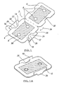
- FIG. 1 there is shown a blank 2 from which a dividing panel for use in the present invention may be formed.
- the dividing panel consists of a main panel 4 and a secondary panel 6 each of which is substantially the same shape and dimensions and provided with venting apertures 8.
- the main panel 4 is provided with edge tabs 10, 12 which are disposed along opposite edges of the main panel and defined partially by fold lines 14, 16 and 18, 20. Where these fold lines terminate inside the bounds of the edge tabs, there are provided substantially u-shaped cut lines 22, 24 which extend into the main panel and define support tabs 26, 28.
- the dividing panel is also provided on both main and secondary panels with a coating 30, 32 of a microwave activatable material such as a sucseptor material well known in the art.
- the dividing panel is formed by folding the secondary panel 6 into coplanar relationship with the main panel as shown by arrow 34, and subsequently deflecting the edge tabs upwardly out of the plane of the main panel so that said edge tabs and said support tabs are in substantially perpendicular relationship to the main panel. It is to be noted that the support tabs are automatically deflected downwardly so that the dividing panel, at least when deposited in the carton in accordance with the invention is supported thereon.
- main panel and the secondary panel may be adhered to one another if required.
- FIG 2 there is shown a blank 40 of a vast number of different types of blank from which a carton according to the present invention may be formed. Indeed, the description of the blank and the carton formed therefrom is provided herein only as example, and it is not considered by the applicant to be essential to the present invention.
- the carton is provided with at least one layer or coating of a susceptor material, a removable panel, a lid and a cavity into which food products may be deposited as hereinafter described.
- carton blank shown is adapted for erection by means of locking tabs
- other types of carton erection adapted for rapid machine erection may be more suitable.
- the flaps of locking tabs can be adhered to the carton.
- the carton blank 40 is provided with a front wall panel 42, a base panel 44, a rear wall panel 46, a lid panel 48 coated with a layer of susceptor material 49.
- Side wall panels 50, 52 are also provided, and the carton is erected by means of locking panels 42A, 42B, 46A, 46B which lock into and through slots 50A, 50B, 52A, 52B provided in the side wall panels.
- a continuous line of weakness 60 is provided which effectively defines a removable panel which is substantially the whole of the base panel 44 and a portion of the rear panel 46 and possibly a small region of the lid panel 48.
- Closure flaps 48A, 48B, 48C are provided on the lid panel 48 as shown.
- FIG. 3 the partially erected carton 70 is shown.
- a first food product ideally a plurality of chipped potatoes or French fries.
- the dividing panel of Figures 1, 1A is deposited over the chipped potatoes, and then a second food product, ideally a piece of uncooked, partially cooked, or wholly cooked battered fish, or a plurality of battered or crumbed fish products such as scampi or the like, is deposited on top of the dividing panel and the lid panel is adheringly closed thereover.
- the closed carton In order to cook the food products sealed inside the carton, the closed carton is upturned so that the base panel 44 is uppermost, the removable panel defined by the continuous line of weakness 60 is torn away so that the volatile products of cooking can vent through the remaining aperture, and further importantly, the second food product is now sandwiched between two susceptor material coatings, one being on the dividing panel above the second food product and one being on the lid panel of the carton.
- the second food product being the battered fish in this instance, requires more intense cooking on both sides, and the fact that this food product is sandwiched between layers of susceptor material permits this.
- the second food product is actually under slight pressure because the first food product actually forces the dividing panel down slightly under the weight of said first food product, and this results in better contact between the susceptor material coatings between which the second food product is sandwiched. The result is a far better cooking, browning or crisping effect on this second food product.
- the first food product is still cooked, browned, crisped or similar by the susceptor material coating which is provided on the surface of the dividing panel on which it is supported.
- venting apertures 8 in the dividing panel provide a convenient means through which the volatile products of cooking developed during the intense and sandwiched cooking of the second food product can escape easily without compromising the quality of either food product.
- the provision of a large area through which the volatile cooking products can escape resulting from the almost total removal of the base panel 44 as the removable panel is torn therefrom facilitates this.
- the shape and size of the dividing panel is matched to the size and shape of the cavity defined within the carton after erection.
- the edge tabs and support tabs will have a tendency to recover from the disposition shown in Figure 1A to that shown in Figure 1 .
- the front and rear wall panels 42, 46 provide a reaction surface against which the edge tabs can abut so as to prevent any elastic recovery thereof.
- the total depth of the edge tabs and support tabs in their erected condition is less than or equal to the depth of the front and rear wall panels.
- apertures are formed between the edge tabs and support tabs and the main and secondary panels of the dividing panel, and these apertures also serve as venting apertures.
- venting apertures 8 referred to in Figs. 1, 1A may additionally be used as purchase means to allow the dividing panel to be easily lifted from within the carton after the food products have been cooked. Most easily this is achieved by means of the user inserting thumb and forefinger through said apertures 8 and lifting said dividing panel from the carton. In the case where the dividing panel consists of only a main panel and layers of susceptor material are patched to either side, such venting apertures may not be present.
- the carton of the present invention can be loaded with one or more food products with the top panel uppermost, the carton then being upturned for cooking and the food subsequently being accessed via the bottom panel of the carton, as shown in figures 1-3 .
- the carton can be loaded with the top panel uppermost, cooked in the same orientation and food can then also be accessed from the carton via the top panel.
- a dividing panel 202 is shown according to a further embodiment of the present invention comprising a main panel 204 and venting apertures 206 to allow the escape of volatile products produced during cooking.
- the peripheral edge of the panel 202 is also provided with recess portions 208 which aid venting and allow a user to grip the panel, in addition to or as an alternative to the venting apertures.
- the entire upper surface of the main panel is provided with microwave activeatable material in this example.
- Figure 6B shows an end view of a further example of a dividing panel 210 according to the present invention.
- the dividing panel 210 has a corrugated first side 212 and a planar second side 214.
- the outer surfaces 216, 218 of the first and second sides can be provided with microwave activeatable material as required. Both sides of the panel can be corrugated if required.
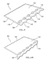
- FIG. 4A there is shown a blank 102 from which a dividing panel 103 according to a further embodiment of the present invention may be formed.
- the dividing panel consists of a main panel 104 and an edge tab 106. Venting apertures 108 are defined along a fold line 110 between main panel 104 and edge tab 106. A free edge 112 of edge tab 106 is provided with recess portions 114 therealong.
- the dividing panel is provided with a coating 116 of microwave activatable material on an underside surface 118 thereof.
- the coating 116 is shown covering only a portion of the panel, it will be appreciated by persons skilled in the art that substantially the whole surface can be coated or any required portion thereof, as is the case in all the examples mentioned herein.
- the dividing panel is formed by deflecting edge tab 106 downwardly out of the plane of the main panel so that edge tab 106 is in substantially perpendicular relationship to main panel 104, as shown in figure 4A . In this erect arrangement, the venting apertures 108 are substantially semi-circular in shape on the main panel and edge tab respectively.
- the dividing panel is located in a carton 70 of the type described above.
- the same reference numerals are used to define the same features as in figures 2 and 3 .
- the carton 70 in figures 5A to 5D has susceptor material 120 on base panel 44 rather than on lid panel 48 as in figures 2 and 3 .
- a first food product is deposited onto base panel 44 of carton 70, which in this example is in the form of french fries 122.
- the dividing panel 103 is located at one end of the carton, with edge tab 106 adjacent side wall panel 52 and main panel 104 protruding outwardly from the carton, as shown in figures 5A and 5B .
- a user gripping the main panel 104 adjacent edge 124 then pushes the dividing panel towards side wall 50 of carton 70, as shown by arrow 126 in figure 5B .
- edge tab 106 contacts the french fries 122 and moves the fries 122 therewith. In this manner, the French fries 122 can be collected together in a more compact arrangement from when they were first deposited into the carton.
- Edge tab 106 therefore acts as a type of rake or scoop.
- first compartment of French fries When edge 124 of the dividing panel is parallel with side wall panel 52, all the french fries 122 are contained between edge tab 106 of the dividing panel and side panel 50 of the carton, thereby defining a first compartment of French fries, as shown in figures 5C and 5D .
- This first compartment has carton susceptor material 120 on a base panel surface such that the fries are browned or crisped on the surface in contact with the susceptor material 120.
- a second compartment 128 is defined adjacent the first compartment on base panel 44 of the carton between edge tab 106 and side wall panel 52 of the carton.
- Edge tab 106 defines a substantially vertical dividing wall between the first and second compartments.
- a further food product which in this example is a portion of fish 130, can be deposited in the second compartment 128. This food product is in contact with carton susceptor material 120 on the base panel of the carton and susceptor material 116 on the underside surface of the dividing panel 103, thereby allowing browning or crisping of both sides of the fish 130 in contact with the susceptor material.
- the food products contained in the first and second compartments can be any type of food products and typically depends on whether the food is required to be in contact with none, one or two susceptor layers. Further compartments can also be provided such that a multi-layer or multi-compartment carton is formed. The further compartments can be horizontally and/or vertically arranged in the carton.
- the orientation of the dividing panel in figures 5A-5D can be reversed, such that when the dividing panel is located in the carton, the edge 124 of main panel 104 protrudes inwardly of the carton. The edge 124 of the main panel is then used to pull the dividing panel across the base of the carton, rather than to push the panel as described above.
- the dividing panel in figures 5A-5D has the advantage that the inherent biasing action of edge tab 106 relative to main panel 104 allows the edge tab to resiliently recover and resume a substantially vertical orientation following movement of the edge tab across the carton base panel. This is because this movement inevitably causes the edge tab to move towards the plane of the main panel.
- the angle which the edge tab makes with the main panel typically depends on the size of the product located under the main panel.
- the edge tab may form an obtuse angle with the main panel with some food products in order to allow maximum contact of the susceptor material with the food product.
- the dividing panel can be turned through ninety degrees from the position shown in figures 5A-5D , such that the edge tab is adjacent the front or rear panels 42 or 46 respectively. This allows venting of volatile products of cooking away from the other food compartment.
- the lid panel 48 of carton 70 is provided with a removable portion 132 defined by frangible portions 134, as shown in figures 5A-5C and 7A, 7B .
- Removable portion 132 can be torn from the remainder of lid panel 48 and folded underneath the base 44 of carton 70, as shown by arrows 136 in figures 7A and 7B . With portion 132 in this folded position, the height of carton in the microwave oven is increased and the heat sink effect adjacent the base of the carton is reduced. In addition, the double thickness of board material adjacent the base of the carton allows a user to handle the carton more easily without the risk of burning their hands.
- FIG 8 a yet further embodiment of a carton 202 according to the present invention is illustrated in cross sectional view.
- the compartments are arranged vertically of each other as in figures 1-3 .
- Dividing panels 204, 206 are provided in carton 202, thereby defining a first compartment 208 between base panel 210, dividing panel 204 and side wall panels 212, 214, a second compartment 216 between dividing panels 204, 206 and side wall panels 212, 214 and a third compartment 218 between top panel 220, dividing panel 206 and side wall panels 212, 214.
- Susceptor material 222 is provided on base panel 210, top panel 220 and an underside surface of dividing panel 204.
- a food product located in first compartment 208 has susceptor material adjacent both sides
- a food product located in the third compartment 218 has susceptor material adjacent a first side
- a food product in the second compartment 216 has no susceptor material in contact therewith.
- This arrangement is particularly advantageous where three or more food products are required to be cooked simultaneously and each food product has different cooking requirements. For example, in a meal such as fish, chips and peas, each food has different cooking requirements.
- the fish typically requires browning on both sides and so is located in compartment 208
- the chips require browning on one side and so are located in compartment 218 and the peas require no browning and so are located in compartment 216.
- the carton and/or dividing panel(s) can be provided in any required size, shape or design but is preferably of such a shape and size to maximise the surface area available for cooking the product, whilst ensuring rotation of the carton on a rotatable plate in the oven is not obstructed, thereby avoiding hot or cold spots in the food product.
- the invention provides a novel carton, insert and food packaging method which allows different food products to be subjected to different cooking conditions within the same carton.
Landscapes
- Engineering & Computer Science (AREA)
- Mechanical Engineering (AREA)
- Life Sciences & Earth Sciences (AREA)
- Food Science & Technology (AREA)
- Package Specialized In Special Use (AREA)
- Cartons (AREA)
- General Preparation And Processing Of Foods (AREA)
- Cookers (AREA)
- Packages (AREA)
Abstract
Description
- This invention relates to a food carton and more specifically to a food carton which includes one or more panels of susceptor material or has one or more panels coated with such a material to allow for crisping, browning and/or cooking of uncooked or partially cooked food pieces deposited in said carton.
- Although the following description relates to the cooking of fish and French fries in the same carton, those skilled in the art will immediately appreciate that the nature of the food to be cooked inside the carton is not relevant to the scope of the invention, except in that the carton is adapted to contain at least two different types of food which may be most beneficially cooked to differing degrees depending on the nature of the particular food. For example, fish and arguably any battered food product has different cooking characteristics to those of French fries. Vegetables have yet further different cooking characteristics to both battered food products and to French fries and/or the like.
-
EP507814 - In use the carton is partially erected, and a first layer of French fries is deposited inside the carton in contact with the lowermost panel, whereafter the layer-divider panels are disposed inside the carton in a manner which allows the deposition of a second layer of French fries on a first one of the layer-divider panels. The second layer-divider panel is then folded over the second layer of French fries to sandwich these between the first and second layer-divider panels, and a final third layer of French fries is deposited on the upper facing surface of the second layer-divider panel. As a final step in the erection, the top panel is closed thus bringing the top panel into intimate contact with the upper surface of the third layer of French fries.
- Each of the top and bottom panels, and the layer-divider panels is provided with a layer of a susceptor material or coated with such a material that during cooking in a microwave, the French fries are heated from both above and below in each compartment defined within the carton.
- It is to be mentioned that the carton described in this patent is adapted to be stood on one of its end panels so that the French fries therein are cooked while being vertically orientated. In this configuration, the uppermost panel (which is one of the side walls of the carton during erection) is provided with lines of perforation or weakness so that parts of this panel can be opened away from the remaining parts to provide one or more ventilation flaps which allow volatile products of cooking to be vented immediately, as opposed to being trapped in any of the compartments within the carton. As in general, the food products cooked in such cartons and indeed cooked in microwave ovens is generally frozen or at least very moist, the volatile cooking products consist solely of steam which if not properly vented can cause the impairment of the food products being cooked, in particular by rendering them soggy and unappetising in appearance.
- It is therefore essential that cartons adapted to contain food products and susceptor panels for cooking such food products be adequately vented during cooking.
- A similar arrangement is disclosed in
US5310977 but the compartments in the vertical stack have different arrangements of susceptor material. - In terms of other relevant prior art,
US4590349 describes a one-piece carton for heating a single layer of variously sized food pieces. The carton includes a layer of microwave active material near the top wall and a similar layer near the bottom wall. The container is manually inverted after the food surface in contact with the microwave active layer has begun to crisp to cause the food piece initially supported by the initial food supporting panel to move under the force of gravity into supporting relationship with the final supporting food panel to crisp the other side of the food piece. - Again, this document essentially describes a carton having only a single compartment at the top and bottom of which are provided susceptor or microwave active material panels (and these terms are to be considered as interchangeable in this specification) to cook food pieces disposed in the carton.
- In
US4836383 , a further one-piece carton is described which is adapted to accommodate a single layer of food supported on a panel which is elevated above the carton bottom such that, in use, the food is elevated above the carton bottom on a false bottom. The panel is provided with a single layer of microwave active material which crispens only the bottom of the food product. -
US4777053 relates to a carton for microwave heating of one layer of food pieces in which a pair of heating panels are mounted on the top and bottom surfaces of the carton. Each panel comprises a semi-conducting heating layer and a microwave shield layer separated therefrom by a spacer wherein said shield is adhesively attached to its corresponding major surface and the heating layer is arranged for direct physical contact with the corresponding upper and respectively, lower surface of the food layer. This arrangement is chosen so that the shield acts as a spaced microwave deflector in order to improve the ratio of dielectric heating to sear. - With the exception of
US4836383 , all the above prior art documents relate to the double sided cooking of food products by providing at least a pair of panels coated or otherwise provided with susceptor material so as to cook the food product sandwiched therebetween. - Indeed,
US4836383 describes a simpler microwave cooking practice wherein only a single side of the food product is cooked. - However, it has heretofore never been considered to contain two or more different types of food products within the same carton for cooking therein, and indeed the prior art tends to make such a concept impractical because of the inherently different cooking characteristics possessed by different food products.
-
US6501059 discloses a tray with recessed regions for the containment of different food products. A lid can be provided for location with the tray. Portions of the lid adjacent the recesses and the bases of the recesses can have different arrangements of microwave shielding regions and microwave absorbing regions. -
WO02/16225 - It is an object of the present invention to provide a carton which allows for differential cooking of different food products deposited within the carton, and in particular to a multi-compartment carton wherein the food products within each compartment can be cooked in a different manner.
- According to the present invention there is provided a carton, said carton having front and rear panels, side panels and top and bottom panels, said carton being further provided with one or more dividing panels internally of the cavity such that at least two compartments are defined therein for the location of one or more food products, one or more surfaces of said panels of one or more of said compartments including a microwave activateable layer or coating which becomes hot in the presence of microwave radiation, the arrangement of the microwave activateable layer is different in the at least two compartments characterised in that at least one of the dividing panels is separate to the carton and includes at least one main panel and at least one edge tab or secondary panel located substantially perpendicular to said main panel.
- Preferably one of the at least two compartments has one of the following arrangements including no microwave activateable layer, one microwave activateable layer, or two microwave activateable layers, and the other of the at least two compartments has one of the remaining two arrangements.
- Thus, the present invention provides a carton wherein the microwave activateable layer is selectively positioned with respect to the foodstuffs to be cooked, thereby allowing simultaneous microwave cooking of the same or a variety of different food products.
- Preferably two or more different food products are provided for simultaneous cooking in each of the compartments of the carton and the food products in the different compartments having different cooking characteristics.
- In one embodiment at least one of the inner surfaces of the top and bottom panels of said carton and at least one surface of one or more of the dividing panels is provided with a microwave activateable layer or coating, the layers or coatings being arranged such that at least one compartment within the cavity is defined by panels on which a layer of microwave activatable material is provided in order that a food product within that compartment is heated from both sides, and at least a further compartment is partially defined by panels, only one of which is provided with a layer of microwave activatable material in order that a food product disposed with that compartment is heated only on one side.
- In one embodiment one or more dividing panels for location in said carton to define two or more compartments therein is separately formed from a further blank and is/are thus a separate component from the carton.
- It is preferable that the dividing panel is manufactured from plain, standard carton board, and consists of at least a main panel and, in one embodiment, a secondary panel. Alternatively, the dividing panel in whatever configuration is manufactured from a board corrugated on one or both sides. Further preferably the corrugated board is provided with one or more layers or coatings of microwave activatable material as previously described.
- The microwave activateable material can be provided on a whole or portion of the at least one surface of the carton or dividing panel as required.
- In an alternative embodiment, the microwave activateable material is in the form of a film or sheet like material which is movable relative or detached from one or more panels of the carton, thereby allowing the film or sheet material to more closely follow the contours of the food product on which it is located.
- The microwave activateable material can be formed from any susceptor material of any required density. In addition, one or more surfaces/portions of the material can be embossed with a particular design or pattern thereon.
- Most preferably the carton is provided with a first food product in a first compartment which is ideally cooked from both sides and a second different food product in a second compartment which is sufficiently cooked by a microwave activatable layer on only one side. Preferably the first food product is a partially cooked battered fish product, and the second food product is a plurality of partially cooked chipped potatoes.
- It is most preferable that one or more of the top panel, bottom panel, rear panel and/or front panel of the carton are provided with lines of weakness which define at least one removable panel or portion.
- In one embodiment the removable panel can be wholly or partially removed and located under a base of the carton to reduce the heat sink effect adjacent the base of the carton, provides the carton with thermal properties and also allows the height of the carton to be increased in the oven.
- Preferably the dividing panel consists of at least one main panel, said main panel being provided with one or more edge tabs which can be deflected out of the plane of the panel to adopt a substantially perpendicular orientation with respect to said panel.
- Most preferably, the completed carton with food products deposited therein is overturned prior to cooking in a microwave oven and a removable panel defined by lines of weakness provided predominantly in any of the compartments, and particularly in the base and rear panels is removed to provide a means of escape for the volatile products of cooking which are given off by said food products.
- Most preferably the dividing panels are provided with venting apertures to facilitate the escape of the volatile products of cooking.
- In one embodiment the dividing panel is of a size which permits insertion into or is positioned in the cavity defined within the carton such that at least one of the perpendicularly orientated edge tabs abut one or more vertically orientated panels or front, rear, or side panels which thus prevent said edge tabs from resiliently recovering under the inherent biasing action of the board from which the dividing panel is constructed.
- It is yet further preferable that the edge tabs are provided along two opposing edges of the dividing panel and include support tabs which are defined by substantially U-shaped cut lines in the main panel of the dividing panel adjacent the edge tabs such that folding of the edges tabs along the edges of said main panel in one direction causes the support tabs to be automatically deflected out of the plane of the main panel in the other direction.
- As will be more clearly understood from the following specific description, the support tabs ensure that the dividing panel is maintained a suitable distance above the lower panel of the carton when inserted therein.
- Most preferably, the dividing panel consists of a main panel and a secondary panel of substantially similar shape to said main panel but provided with one or more cut-out portions in areas corresponding to the areas of the main panel which ultimately form the support tabs, the dividing panel being formed by folding the secondary panel into co-planar relationship with the main panel and deflecting the edge tabs out of the plane of both said panels into substantially perpendicular orientation with respect thereto.
- In a further embodiment, the dividing panel is of a size which permits insertion into the cavity defined within the carton and the at least one perpendicularly orientated edge tab is provided a spaced distance between opposite vertically orientated panels of the carton. Preferably, with the dividing panel arranged in this manner, at least two compartments are formed in the carton, one compartment either side of the edge tab. As such, at least two compartments are formed adjacent the top and/or bottom panel of the carton.
- Preferably one or more venting apertures are provided in the main panel and/or on the at least one edge tab of the dividing panel to allow volatile products of cooking to escape from one compartment into another compartment.
- In one embodiment these venting apertures are provided along a fold line of the dividing panel between the main panel and the at least one edge tab. Preferably when the edge tab is deflected to adopt a substantially vertical orientation, the venting apertures are semi-circular in shape on the main panel and the edge tab.
- Preferably at least the free edge of the dividing panel or edge tab is non-linear, thereby providing venting gaps or apertures, such as for example between the top or bottom panel of the carton and the free edge of the edge tab.
- Further preferably the free edge of the edge tab is provided with U-shaped or concave recesses thereon to form the gaps or apertures.
- Preferably the main panel of the dividing panel is of such dimensions that when formed, it only covers a portion of said bottom or top panel of the carton. This allows the dividing panel to be moved within the carton relative to the said top and/or bottom panels. In this manner, a first food product located in the carton can be moved within the carton to a required location using the dividing panel.
- Further preferably the edge tab of the dividing panel contacts the first food product and moves said food product with the dividing panel, thereby acting as a form of scoop or rake.
- Adjacent compartments of the carton can be located substantially vertically of each other and/or can be located substantially horizontally of each other.
- According to a second aspect of the present invention there is provided a blank for forming a carton as hereinbefore described, said blank defining a plurality of panels with fold lines therebetween such that in its erected condition said carton has front and rear panels, side panels and top and bottom panels which define a cavity into which a food product may be deposited.
- In accordance with a further aspect of the invention there is provided a dividing panel according to any of the embodiments as previously described.
- In accordance with a yet further aspect of the invention, there is provided a method of packaging at least first and second food products in a carton, said carton having front and rear panels, side panels and top and bottom panels, said method including the steps of depositing a first food product onto the base of said carton, locating a dividing panel over and/or adjacent said first food product to define a first compartment, depositing a second food product onto an upper surface of the dividing panel or adjacent said first compartment in a second compartment, one or more surfaces of said panels including a microwave activateable layer or coating which becomes hot in the presence of microwave radiation, the arrangement of the microwave activateable layer being different in the at least two compartments, characterised in that at least one of the dividing panels is separate to the carton and includes at least one main panel and at least one edge tab or secondary panel located substantially perpendicular to said main panel.
- In one aspect of the invention, if a multi-layered carton is provided, some of the food products in the carton may be provided so as not to contact any microwave activateable layer. This is particularly advantageous, for example, if the carton contains battered fish, chips and vegetables to form a meal, and only the fish and chips require browning or require a crisp outer surface, the fish and/or chips are provided in the upper and lower compartments in contact with the top and bottom panels and the vegetables are provided in an intermediate layer between two or more dividing panels.
- Embodiments of the invention will now be described by way of example with reference to the accompanying drawings wherein:
-
Figure 1 shows a plan view in perspective of a blank from which a dividing panel used in the carton according to one embodiment of the present invention is erected, -
Figure 1A shows a perspective view of the completed dividing panel, -
Figure 2 shows a plan view of a blank from which the carton according to the invention may be erected, -
Figure 3 shows a carton partially erected from the blank ofFigure 2 , -
Figure 4 shows a plan view in perspective of a blank from which a dividing panel used in the carton according to a further embodiment of the present invention is erected, -
Figure 4A shows a perspective view of the erect or formed dividing panel, -
Figures 5A-5C show a carton in which the dividing panel infigure 4A is to be located therein in various stages, -
Figure 5D shows a cross sectional view of the carton containing the blank and food products in a final stage; -
Figure 6A is plan view of a dividing panel according to a further embodiment of the present invention; -
Figure 6B is an end view of a dividing panel according to a yet further aspect of the present invention; -
Figures 7A and 7B illustrate different stages of use of the carton; and -
Figure 8 illustrates a cross sectional view of a further embodiment of the present invention. - Referring firstly to
Figure 1 there is shown a blank 2 from which a dividing panel for use in the present invention may be formed. The dividing panel consists of amain panel 4 and asecondary panel 6 each of which is substantially the same shape and dimensions and provided with ventingapertures 8. Themain panel 4 is provided withedge tabs fold lines support tabs - The dividing panel is also provided on both main and secondary panels with a
coating secondary panel 6 into coplanar relationship with the main panel as shown byarrow 34, and subsequently deflecting the edge tabs upwardly out of the plane of the main panel so that said edge tabs and said support tabs are in substantially perpendicular relationship to the main panel. It is to be noted that the support tabs are automatically deflected downwardly so that the dividing panel, at least when deposited in the carton in accordance with the invention is supported thereon. - It is also to be mentioned that the main panel and the secondary panel may be adhered to one another if required.
- Referring to
figure 2 there is shown a blank 40 of a vast number of different types of blank from which a carton according to the present invention may be formed. Indeed, the description of the blank and the carton formed therefrom is provided herein only as example, and it is not considered by the applicant to be essential to the present invention. In this embodiment the carton is provided with at least one layer or coating of a susceptor material, a removable panel, a lid and a cavity into which food products may be deposited as hereinafter described. - Furthermore, although the carton blank shown is adapted for erection by means of locking tabs, other types of carton erection adapted for rapid machine erection may be more suitable. For example, the flaps of locking tabs can be adhered to the carton.
- The carton blank 40 is provided with a
front wall panel 42, abase panel 44, arear wall panel 46, alid panel 48 coated with a layer ofsusceptor material 49.Side wall panels panels slots weakness 60 is provided which effectively defines a removable panel which is substantially the whole of thebase panel 44 and a portion of therear panel 46 and possibly a small region of thelid panel 48. Closure flaps 48A, 48B, 48C are provided on thelid panel 48 as shown. - Referring now to
figure 3 , the partially erectedcarton 70 is shown. Into this carton is deposited a first food product, ideally a plurality of chipped potatoes or French fries. Thereafter the dividing panel ofFigures 1, 1A is deposited over the chipped potatoes, and then a second food product, ideally a piece of uncooked, partially cooked, or wholly cooked battered fish, or a plurality of battered or crumbed fish products such as scampi or the like, is deposited on top of the dividing panel and the lid panel is adheringly closed thereover. - In order to cook the food products sealed inside the carton, the closed carton is upturned so that the
base panel 44 is uppermost, the removable panel defined by the continuous line ofweakness 60 is torn away so that the volatile products of cooking can vent through the remaining aperture, and further importantly, the second food product is now sandwiched between two susceptor material coatings, one being on the dividing panel above the second food product and one being on the lid panel of the carton. In accordance with the invention, the second food product, being the battered fish in this instance, requires more intense cooking on both sides, and the fact that this food product is sandwiched between layers of susceptor material permits this. - It is of yet further importance that the second food product is actually under slight pressure because the first food product actually forces the dividing panel down slightly under the weight of said first food product, and this results in better contact between the susceptor material coatings between which the second food product is sandwiched. The result is a far better cooking, browning or crisping effect on this second food product. Of course the first food product is still cooked, browned, crisped or similar by the susceptor material coating which is provided on the surface of the dividing panel on which it is supported.
- Also the venting
apertures 8 in the dividing panel provide a convenient means through which the volatile products of cooking developed during the intense and sandwiched cooking of the second food product can escape easily without compromising the quality of either food product. The provision of a large area through which the volatile cooking products can escape resulting from the almost total removal of thebase panel 44 as the removable panel is torn therefrom facilitates this. - It is important to note that the shape and size of the dividing panel is matched to the size and shape of the cavity defined within the carton after erection. As the dividing panel will conventionally be manufactured of a board or card material, the edge tabs and support tabs will have a tendency to recover from the disposition shown in
Figure 1A to that shown inFigure 1 . However, once the dividing panel is disposed in the carton cavity, the front andrear wall panels - The venting
apertures 8 referred to inFigs. 1, 1A (where the dividing panel is of the main and secondary panel construction depicted) may additionally be used as purchase means to allow the dividing panel to be easily lifted from within the carton after the food products have been cooked. Most easily this is achieved by means of the user inserting thumb and forefinger through saidapertures 8 and lifting said dividing panel from the carton. In the case where the dividing panel consists of only a main panel and layers of susceptor material are patched to either side, such venting apertures may not be present. - The carton of the present invention can be loaded with one or more food products with the top panel uppermost, the carton then being upturned for cooking and the food subsequently being accessed via the bottom panel of the carton, as shown in
figures 1-3 . Alternatively, the carton can be loaded with the top panel uppermost, cooked in the same orientation and food can then also be accessed from the carton via the top panel. - Referring to
figure 6A , a dividingpanel 202 is shown according to a further embodiment of the present invention comprising amain panel 204 and ventingapertures 206 to allow the escape of volatile products produced during cooking. The peripheral edge of thepanel 202 is also provided withrecess portions 208 which aid venting and allow a user to grip the panel, in addition to or as an alternative to the venting apertures. The entire upper surface of the main panel is provided with microwave activeatable material in this example. -
Figure 6B shows an end view of a further example of a dividingpanel 210 according to the present invention. The dividingpanel 210 has a corrugatedfirst side 212 and a planarsecond side 214. Theouter surfaces - Referring to
figures 4 and 4A , there is shown a blank 102 from which adividing panel 103 according to a further embodiment of the present invention may be formed. The dividing panel consists of amain panel 104 and anedge tab 106. Ventingapertures 108 are defined along afold line 110 betweenmain panel 104 andedge tab 106. Afree edge 112 ofedge tab 106 is provided withrecess portions 114 therealong. - The dividing panel is provided with a
coating 116 of microwave activatable material on anunderside surface 118 thereof. Although thecoating 116 is shown covering only a portion of the panel, it will be appreciated by persons skilled in the art that substantially the whole surface can be coated or any required portion thereof, as is the case in all the examples mentioned herein. The dividing panel is formed by deflectingedge tab 106 downwardly out of the plane of the main panel so thatedge tab 106 is in substantially perpendicular relationship tomain panel 104, as shown infigure 4A . In this erect arrangement, the ventingapertures 108 are substantially semi-circular in shape on the main panel and edge tab respectively. - Referring to
figures 5A to 5D , the dividing panel is located in acarton 70 of the type described above. The same reference numerals are used to define the same features as infigures 2 and3 . Thecarton 70 infigures 5A to 5D hassusceptor material 120 onbase panel 44 rather than onlid panel 48 as infigures 2 and3 . - A first food product is deposited onto
base panel 44 ofcarton 70, which in this example is in the form offrench fries 122. The dividingpanel 103 is located at one end of the carton, withedge tab 106 adjacentside wall panel 52 andmain panel 104 protruding outwardly from the carton, as shown infigures 5A and 5B . A user gripping themain panel 104adjacent edge 124 then pushes the dividing panel towardsside wall 50 ofcarton 70, as shown byarrow 126 infigure 5B . As the dividing panel moves across the base panel surface of the carton,edge tab 106 contacts thefrench fries 122 and moves thefries 122 therewith. In this manner, theFrench fries 122 can be collected together in a more compact arrangement from when they were first deposited into the carton.Edge tab 106 therefore acts as a type of rake or scoop. - When
edge 124 of the dividing panel is parallel withside wall panel 52, all thefrench fries 122 are contained betweenedge tab 106 of the dividing panel andside panel 50 of the carton, thereby defining a first compartment of French fries, as shown infigures 5C and 5D . This first compartment hascarton susceptor material 120 on a base panel surface such that the fries are browned or crisped on the surface in contact with thesusceptor material 120. - A
second compartment 128 is defined adjacent the first compartment onbase panel 44 of the carton betweenedge tab 106 andside wall panel 52 of the carton.Edge tab 106 defines a substantially vertical dividing wall between the first and second compartments. A further food product, which in this example is a portion offish 130, can be deposited in thesecond compartment 128. This food product is in contact withcarton susceptor material 120 on the base panel of the carton andsusceptor material 116 on the underside surface of the dividingpanel 103, thereby allowing browning or crisping of both sides of thefish 130 in contact with the susceptor material. - It will be appreciated that the food products contained in the first and second compartments can be any type of food products and typically depends on whether the food is required to be in contact with none, one or two susceptor layers. Further compartments can also be provided such that a multi-layer or multi-compartment carton is formed. The further compartments can be horizontally and/or vertically arranged in the carton.
- It will also be appreciated that the orientation of the dividing panel in
figures 5A-5D can be reversed, such that when the dividing panel is located in the carton, theedge 124 ofmain panel 104 protrudes inwardly of the carton. Theedge 124 of the main panel is then used to pull the dividing panel across the base of the carton, rather than to push the panel as described above. However, the dividing panel infigures 5A-5D has the advantage that the inherent biasing action ofedge tab 106 relative tomain panel 104 allows the edge tab to resiliently recover and resume a substantially vertical orientation following movement of the edge tab across the carton base panel. This is because this movement inevitably causes the edge tab to move towards the plane of the main panel. The angle which the edge tab makes with the main panel typically depends on the size of the product located under the main panel. For example, the edge tab may form an obtuse angle with the main panel with some food products in order to allow maximum contact of the susceptor material with the food product. - Furthermore, the dividing panel can be turned through ninety degrees from the position shown in
figures 5A-5D , such that the edge tab is adjacent the front orrear panels - In a further embodiment, the
lid panel 48 ofcarton 70 is provided with aremovable portion 132 defined byfrangible portions 134, as shown infigures 5A-5C and7A, 7B .Removable portion 132 can be torn from the remainder oflid panel 48 and folded underneath thebase 44 ofcarton 70, as shown byarrows 136 infigures 7A and 7B . Withportion 132 in this folded position, the height of carton in the microwave oven is increased and the heat sink effect adjacent the base of the carton is reduced. In addition, the double thickness of board material adjacent the base of the carton allows a user to handle the carton more easily without the risk of burning their hands. - Referring to
figure 8 , a yet further embodiment of acarton 202 according to the present invention is illustrated in cross sectional view. In this embodiment the compartments are arranged vertically of each other as infigures 1-3 . Dividingpanels carton 202, thereby defining afirst compartment 208 betweenbase panel 210, dividingpanel 204 andside wall panels second compartment 216 between dividingpanels side wall panels third compartment 218 betweentop panel 220, dividingpanel 206 andside wall panels -
Susceptor material 222 is provided onbase panel 210,top panel 220 and an underside surface of dividingpanel 204. As such, a food product located infirst compartment 208 has susceptor material adjacent both sides, a food product located in thethird compartment 218 has susceptor material adjacent a first side and a food product in thesecond compartment 216 has no susceptor material in contact therewith. This arrangement is particularly advantageous where three or more food products are required to be cooked simultaneously and each food product has different cooking requirements. For example, in a meal such as fish, chips and peas, each food has different cooking requirements. The fish typically requires browning on both sides and so is located incompartment 208, the chips require browning on one side and so are located incompartment 218 and the peas require no browning and so are located incompartment 216. - It will be appreciated that any number of compartments can be provided as required.
- The carton and/or dividing panel(s) can be provided in any required size, shape or design but is preferably of such a shape and size to maximise the surface area available for cooking the product, whilst ensuring rotation of the carton on a rotatable plate in the oven is not obstructed, thereby avoiding hot or cold spots in the food product.
- Accordingly, the invention provides a novel carton, insert and food packaging method which allows different food products to be subjected to different cooking conditions within the same carton.
Claims (24)
- A carton (70), said carton having front and rear panels (42, 46), side panels (50,52) and top and bottom panels (48, 44), said carton being further provided with one or more dividing panels (202; 210;103) internally of the cavity such that at least two compartments are defined therein for the location of one or more food products (122, 130), one or more surfaces of said panels of one or more of said compartments including a microwave activateable layer or coating (30, 32; 49; 116) which becomes hot in the presence of microwave radiation, the arrangement of the microwave activateable layer being different in the at least two compartments, characterised in that at least one of the dividing panels (202; 210; 103) is separate to the carton and includes at least one main panel (104; 4) and at least one edge tab (106, 10, 12) or secondary panel located substantially perpendicular to said main panel.
- A carton according to claim 1 characterised in that one of the at least two compartments has one of the following arrangements including no microwave activateable layer (30, 32; 49; 116), one microwave activateable layer (30, 32; 49; 116), or two microwave activateable layers (30, 32; 49; 116), and the other of the at least two compartments has one of the remaining two arrangements.
- A carton according to claim 1 characterised in that each of said at least two compartments has a single microwave activateable layer (30, 32; 49; 116) but said layer is provided on different panels in the at least two different compartments.
- A carton according to claim 1 characterised in that two or more different food products (122, 130) can be provided for simultaneous cooking in each of the compartments of the carton, the food products in the different compartments having different cooking characteristics.
- A carton according to claim 1 characterised that in one of said compartments the food products (122, 130) can be heated from a single side and in a further compartment the food products (122, 130) can be heated from both sides.
- A carton according to claim 5 characterised in that the food product (122, 130) heated from a single side is a plurality of partially cooked potatoes and the food product heated from both sides is a partially cooked battered fish product.
- A carton according to claim 1 characterised in that the dividing panel (103) includes a main panel (104; 4) with one or more edge tabs (106, 10, 12), the edge tabs capable of being deflected out of the plane of the main panel to adopt the substantially perpendicular orientation with respect to said panel (104; 4).
- A carton according to claim 1 characterised in that the dividing panel (202, 210, 103) is of a size which permits insertion into or is positioned in the cavity defined by the carton such that at least one of the perpendicular orientated edge tabs (106, 10, 12) abut one or more vertically orientated carton panels (42, 46, 50, 52).
- A carton according to claim 1 characterised in that the dividing panel (202, 210, 103) is of a size which permits insertion into or is positioned in the cavity defined by the carton such that at least one of the perpendicular orientated edge tabs (106, 10, 12) is provided a spaced distance between opposite vertically orientated panels (42, 46, 50, 52) of the carton.
- A carton according to claim 1 characterised in that the edge tabs (10, 12) are provided along two opposing edges of the dividing panel and include support tabs (26, 28) which are defined by substantially U-shaped cut lines (22, 24) in the main panel (4) adjacent the edge tabs (10, 12), such that folding of the edge tabs in one direction causes the support tabs (26, 28) to be deflected out of the plane of the main panel (4) in the other direction.
- A carton according to claim 10 characterised in that the dividing panel includes a main panel (4) and a secondary panel (6) of substantially similar shape, the secondary panel (6) having one or more cut out portions (22, 24) in areas corresponding to the areas of the main panel which ultimately form the support tabs (26, 28), the dividing panel being formed by folding the secondary panel (6) into co-planar relationship with the main panel (4) and deflecting the edge tabs (10, 12) out of the plane of both of said panels into substantially perpendicular orientation with respect thereto.
- A carton according to claim 1 characterised in that the dividing panel (102, 202, 210) is formed from a board material corrugated on one or both sides.
- A carton according to claim 1 characterised in that the dividing panel (102, 202, 210) is provided with one or more venting apertures (8) therein.
- A carton according to claim 13 characterised in that the venting apertures (8) are provided along a fold line (110) of the dividing panel (102) between the main panel (104) and at least one edge tab (116).
- A carton according to claim 13 characterised in that a free edge (114) of the dividing panel (102) is non-linear to provide one or more venting apertures or gaps.
- A carton according to claim 1 characterised in that the main panel of the dividing panel (202, 210, 103) is of such dimensions that when formed, it only covers a portion of said bottom or top panel (48, 44) of the carton.
- A carton according to claim 16 characterised in that the dividing panel (202, 210, 103) is movable in said carton relative to said top and/or bottom panels (48, 44).
- A carton according to claim 1 characterised in that the microwave activateable layer (30, 32, 49, 116) is in the form of a film or sheet like material which is movable relative to or detached from the panels of the carton.
- A carton according to claim 1 characterised in that one or more portions of the microwave activateable material (30, 32, 49, 116) is embossed with a particular design or pattern.
- A carton according to claim 1 characterised in that one or more of the top (48), bottom (44), rear (46) and/or front (42) panels of the carton are provided with lines of weakness (134) which define at least one removable panel (132).
- A carton according to claim 20 characterised in that the removable panel (132) is partially or wholly removed and located under a base (44) of the carton.
- A carton according to claim 20 characterised in that the removable panel (132) can be removed during cooking to provide a means of escape of the volatile products produced by the food products (122, 130) during cooking.
- A carton according to claim 1 characterised in that at least two compartments are provided adjacent the bottom (44) and/or top panel (48) of the carton.
- A method of packaging at least first and second food products (122, 130) in a carton (70), said carton (70) having front and rear panels (42, 46), side panels (50, 52) and top and bottom panels (48, 44), said method including the steps of depositing a first food product onto the base (44) of said carton, locating a dividing panel (202, 210, 103) over and/or adjacent said first food product to define a first compartment, depositing a second food product onto an upper surface of the dividing panel or adjacent said first compartment in a second compartment, one or more surfaces of said panels including a microwave activateable layer (30, 32, 49, 116) or coating which becomes hot in the presence of microwave radiation, the arrangement of the microwave activateable layer being different in the at least two compartments, characterised in that at least one of the dividing panels (202; 210; 103) is separate to the carton and includes at least one main panel (104; 4) and at least one edge tab (106, 10, 12) or secondary panel located substantially perpendicular to said main panel.
Applications Claiming Priority (2)
| Application Number | Priority Date | Filing Date | Title |
|---|---|---|---|
| GBGB0304347.8A GB0304347D0 (en) | 2003-02-26 | 2003-02-26 | Food carton |
| GB0304347 | 2003-02-26 |
Publications (3)
| Publication Number | Publication Date |
|---|---|
| EP1452458A2 EP1452458A2 (en) | 2004-09-01 |
| EP1452458A3 EP1452458A3 (en) | 2004-11-03 |
| EP1452458B1 true EP1452458B1 (en) | 2008-02-20 |
Family
ID=9953671
Family Applications (1)
| Application Number | Title | Priority Date | Filing Date |
|---|---|---|---|
| EP04251031A Expired - Lifetime EP1452458B1 (en) | 2003-02-26 | 2004-02-25 | Food carton |
Country Status (5)
| Country | Link |
|---|---|
| EP (1) | EP1452458B1 (en) |
| AT (1) | ATE386694T1 (en) |
| DE (1) | DE602004011845D1 (en) |
| DK (1) | DK1452458T3 (en) |
| GB (1) | GB0304347D0 (en) |
Cited By (2)
| Publication number | Priority date | Publication date | Assignee | Title |
|---|---|---|---|---|
| US9499296B2 (en) | 2013-07-25 | 2016-11-22 | Graphic Packaging International, Inc. | Carton for a food product |
| EP3995407A2 (en) | 2020-11-04 | 2022-05-11 | Asklepios Kliniken GmbH & Co. KGaA | Folding box for holding a section tray |
Families Citing this family (27)
| Publication number | Priority date | Publication date | Assignee | Title |
|---|---|---|---|---|
| FR2876675B1 (en) * | 2004-10-15 | 2008-06-20 | Francois Berthault | DEVICE FOR CONDITIONING AND COOKING EXTRUDED CEREALS OR THE LIKE |
| EP1888430B1 (en) | 2005-04-11 | 2011-02-09 | Graphic Packaging International, Inc. | Microwavable food package having an easy-open feature |
| US7345262B2 (en) | 2005-11-07 | 2008-03-18 | Graphic Packaging International, Inc. | Microwave interactive display package |
| US7414230B2 (en) | 2005-12-08 | 2008-08-19 | Graphic Packaging International, Inc. | Package with removable portion |
| CA2694535C (en) | 2007-08-13 | 2013-05-07 | Graphic Packaging International, Inc. | Package with enlarged base |
| US9957080B2 (en) | 2013-09-25 | 2018-05-01 | Graphic Packaging International, Llc | Reinforced package |
| JP6426719B2 (en) | 2013-09-25 | 2018-11-21 | グラフィック パッケージング インターナショナル エルエルシー | Reinforcement package |
| US9771176B2 (en) | 2013-09-25 | 2017-09-26 | Graphic Packaging International, Inc. | Reinforced package |
| EP3209577B1 (en) | 2014-10-21 | 2020-12-02 | Graphic Packaging International, LLC | Package for a product, blank and liner in combination, method |
| CN107530998B (en) | 2015-04-29 | 2020-05-19 | 印刷包装国际有限责任公司 | Method and system for forming a package |
| CN107531379B (en) | 2015-04-29 | 2019-05-03 | 印刷包装国际有限责任公司 | Method and system for forming a package |
| CN107848723B (en) | 2015-07-14 | 2020-09-22 | 印刷包装国际有限责任公司 | Method and system for forming packages |
| MX2018001983A (en) | 2015-08-21 | 2018-05-28 | Graphic Packaging Int Llc | Reinforced package. |
| WO2019032436A1 (en) | 2017-08-09 | 2019-02-14 | Graphic Packaging International, Llc | Method and system for forming packages |
| EP3678953B1 (en) | 2017-09-06 | 2024-10-02 | Graphic Packaging International, LLC | Carton with at least one holder, blank and method associated |
| USD842095S1 (en) | 2017-10-10 | 2019-03-05 | Graphic Packaging International, Llc | Carton |
| MX2021000248A (en) | 2018-07-09 | 2021-03-25 | Graphic Packaging Int Llc | Method and system for forming packages. |
| CA3105032C (en) | 2018-08-06 | 2023-03-14 | Graphic Packaging International, Llc | Container with at least one compartment |
| WO2020159818A1 (en) | 2019-01-28 | 2020-08-06 | Graphic Packaging International, Llc | Reinforced package |
| EP3931117B1 (en) | 2019-02-28 | 2024-09-25 | Graphic Packaging International, LLC | Carton for a food product |
| USD899246S1 (en) | 2019-04-24 | 2020-10-20 | Graphic Packaging International, Llc | Carton |
| USD1042113S1 (en) | 2020-01-24 | 2024-09-17 | Graphic Packaging International, Llc | Reinforcing carton |
| USD999055S1 (en) | 2020-10-29 | 2023-09-19 | Graphic Packaging International, Llc | Carton |
| MX2023007138A (en) | 2020-12-22 | 2023-06-27 | Graphic Packaging Int Llc | End flap engagement assembly for erecting cartons and related systems and methods. |
| US11905080B2 (en) | 2021-08-11 | 2024-02-20 | Graphic Packaging International, Llc | Carton for food products |
| USD1029629S1 (en) | 2022-05-31 | 2024-06-04 | Graphic Packaging International, Llc | Carton |
| USD1091334S1 (en) | 2023-05-11 | 2025-09-02 | Graphic Packaging International, Llc | Tray with divider features |
Family Cites Families (9)
| Publication number | Priority date | Publication date | Assignee | Title |
|---|---|---|---|---|
| US4592914A (en) * | 1983-06-15 | 1986-06-03 | James River-Dixie/Northern, Inc. | Two-blank disposable container for microwave food cooking |
| US5310977A (en) * | 1989-02-03 | 1994-05-10 | Minnesota Mining And Manufacturing Company | Configured microwave susceptor |
| AU5832190A (en) * | 1989-06-05 | 1991-01-07 | Mccain Foods Limited | Microwave oven package |
| US5718370A (en) * | 1996-05-23 | 1998-02-17 | Fort James Corporation | Partially shielded microwave heating container |
| GB9915801D0 (en) * | 1999-07-07 | 1999-09-08 | Bonar Imca Ltd | Package for foodstuff |
| GB9925374D0 (en) * | 1999-10-27 | 1999-12-29 | Mso Limited | A microwave cooking package |
| WO2002016225A1 (en) * | 2000-08-22 | 2002-02-28 | Mugibayashi, Yasuko | Cold-retention temperature adjusting container for microwave ovens |
| GB2368507A (en) * | 2000-10-25 | 2002-05-01 | Boxes | Microwave packaging |
| US7601408B2 (en) * | 2002-08-02 | 2009-10-13 | Robert C. Young | Microwave susceptor with fluid absorbent structure |
-
2003
- 2003-02-26 GB GBGB0304347.8A patent/GB0304347D0/en not_active Ceased
-
2004
- 2004-02-25 EP EP04251031A patent/EP1452458B1/en not_active Expired - Lifetime
- 2004-02-25 AT AT04251031T patent/ATE386694T1/en not_active IP Right Cessation
- 2004-02-25 DK DK04251031T patent/DK1452458T3/en active
- 2004-02-25 DE DE602004011845T patent/DE602004011845D1/en not_active Expired - Lifetime
Cited By (3)
| Publication number | Priority date | Publication date | Assignee | Title |
|---|---|---|---|---|
| US9499296B2 (en) | 2013-07-25 | 2016-11-22 | Graphic Packaging International, Inc. | Carton for a food product |
| EP3995407A2 (en) | 2020-11-04 | 2022-05-11 | Asklepios Kliniken GmbH & Co. KGaA | Folding box for holding a section tray |
| EP3995407A3 (en) * | 2020-11-04 | 2022-09-07 | Asklepios Kliniken GmbH & Co. KGaA | Folding box for holding a section tray |
Also Published As
| Publication number | Publication date |
|---|---|
| GB0304347D0 (en) | 2003-04-02 |
| DK1452458T3 (en) | 2008-06-16 |
| EP1452458A2 (en) | 2004-09-01 |
| DE602004011845D1 (en) | 2008-04-03 |
| EP1452458A3 (en) | 2004-11-03 |
| ATE386694T1 (en) | 2008-03-15 |
Similar Documents
| Publication | Publication Date | Title |
|---|---|---|
| EP1452458B1 (en) | Food carton | |
| EP0507814B1 (en) | Microwave food carton having two integral layer-divider panels and blank therefor | |
| US4594492A (en) | Microwave package including a resiliently biased browning layer | |
| US5510132A (en) | Method for cooking a food item in microwave heating package having end flaps for elevating and venting the package | |
| CA1231321A (en) | Two-blank disposable container for microwave food cooking and method for making | |
| AU645034B2 (en) | Improvements relating to packaging containers | |
| EP2493263B1 (en) | Microwave heating construct | |
| US5484984A (en) | Ovenable food package including a base with depending leg member and a plurality of raised portions and associated food packages | |
| US4687104A (en) | Microwave carton | |
| US4877932A (en) | Microwave container assembly | |
| EP2610196B1 (en) | Microwave heating construct and method of using same | |
| US5045330A (en) | Biased food contact container and container insert | |
| EP2077240B1 (en) | Microwavable construct for heating, browning and crisping rounded food items | |
| US4836438A (en) | Ovenable carton with handles | |
| CA2067161C (en) | Microwave food package | |
| EP3883860B1 (en) | Adjustable tray, blank for forming a tray and method of forming a tray | |
| US20070241102A1 (en) | Apparatus for microwave cooking of a food product | |
| US5369256A (en) | Packaging capable of microwave heating | |
| EP1067055A2 (en) | Food packaging for microwave cooking | |
| WO1990015514A1 (en) | Microwave oven package | |
| CA3116209C (en) | Adjustable tray | |
| IE83925B1 (en) | A package |
Legal Events
| Date | Code | Title | Description |
|---|---|---|---|
| PUAI | Public reference made under article 153(3) epc to a published international application that has entered the european phase |
Free format text: ORIGINAL CODE: 0009012 |
|
| AK | Designated contracting states |
Kind code of ref document: A2 Designated state(s): AT BE BG CH CY CZ DE DK EE ES FI FR GB GR HU IE IT LI LU MC NL PT RO SE SI SK TR |
|
| AX | Request for extension of the european patent |
Extension state: AL LT LV MK |
|
| PUAL | Search report despatched |
Free format text: ORIGINAL CODE: 0009013 |
|
| RIC1 | Information provided on ipc code assigned before grant |
Ipc: 7B 65D 5/48 B Ipc: 7B 65D 81/34 A Ipc: 7B 65D 5/54 B |
|
| AK | Designated contracting states |
Kind code of ref document: A3 Designated state(s): AT BE BG CH CY CZ DE DK EE ES FI FR GB GR HU IE IT LI LU MC NL PT RO SE SI SK TR |
|
| AX | Request for extension of the european patent |
Extension state: AL LT LV MK |
|
| 17P | Request for examination filed |
Effective date: 20050517 |
|
| AKX | Designation fees paid |
Designated state(s): AT BE BG CH CY CZ DE DK EE ES FI FR GB GR HU IE IT LI LU MC NL PT RO SE SI SK TR |
|
| 17Q | First examination report despatched |
Effective date: 20050822 |
|
| GRAP | Despatch of communication of intention to grant a patent |
Free format text: ORIGINAL CODE: EPIDOSNIGR1 |
|
| RAP1 | Party data changed (applicant data changed or rights of an application transferred) |
Owner name: YOUNG'S BLUECREST SEAFOOD LIMITED |
|
| GRAS | Grant fee paid |
Free format text: ORIGINAL CODE: EPIDOSNIGR3 |
|
| GRAA | (expected) grant |
Free format text: ORIGINAL CODE: 0009210 |
|
| AK | Designated contracting states |
Kind code of ref document: B1 Designated state(s): AT BE BG CH CY CZ DE DK EE ES FI FR GB GR HU IE IT LI LU MC NL PT RO SE SI SK TR |
|
| REG | Reference to a national code |
Ref country code: GB Ref legal event code: FG4D |
|
| RIN1 | Information on inventor provided before grant (corrected) |
Inventor name: PETERS, KEITHC/O POLESTAR JOWETTS LTD Inventor name: BORRILL, VANESSAC/O YOUNGS BLUECREST SEAFOOD LTD |
|
| REG | Reference to a national code |
Ref country code: CH Ref legal event code: EP |
|
| REG | Reference to a national code |
Ref country code: IE Ref legal event code: FG4D |
|
| REF | Corresponds to: |
Ref document number: 602004011845 Country of ref document: DE Date of ref document: 20080403 Kind code of ref document: P |
|
| REG | Reference to a national code |
Ref country code: SE Ref legal event code: TRGR |
|
| REG | Reference to a national code |
Ref country code: DK Ref legal event code: T3 |
|
| PG25 | Lapsed in a contracting state [announced via postgrant information from national office to epo] |
Ref country code: ES Free format text: LAPSE BECAUSE OF FAILURE TO SUBMIT A TRANSLATION OF THE DESCRIPTION OR TO PAY THE FEE WITHIN THE PRESCRIBED TIME-LIMIT Effective date: 20080531 |
|
| NLV1 | Nl: lapsed or annulled due to failure to fulfill the requirements of art. 29p and 29m of the patents act | ||
| PG25 | Lapsed in a contracting state [announced via postgrant information from national office to epo] |
Ref country code: AT Free format text: LAPSE BECAUSE OF FAILURE TO SUBMIT A TRANSLATION OF THE DESCRIPTION OR TO PAY THE FEE WITHIN THE PRESCRIBED TIME-LIMIT Effective date: 20080220 |
|
| ET | Fr: translation filed | ||
| REG | Reference to a national code |
Ref country code: HU Ref legal event code: AG4A Ref document number: E003381 Country of ref document: HU |
|
| PG25 | Lapsed in a contracting state [announced via postgrant information from national office to epo] |
Ref country code: SI Free format text: LAPSE BECAUSE OF FAILURE TO SUBMIT A TRANSLATION OF THE DESCRIPTION OR TO PAY THE FEE WITHIN THE PRESCRIBED TIME-LIMIT Effective date: 20080220 Ref country code: BE Free format text: LAPSE BECAUSE OF FAILURE TO SUBMIT A TRANSLATION OF THE DESCRIPTION OR TO PAY THE FEE WITHIN THE PRESCRIBED TIME-LIMIT Effective date: 20080220 |
|
| REG | Reference to a national code |
Ref country code: CH Ref legal event code: PL |
|
| PG25 | Lapsed in a contracting state [announced via postgrant information from national office to epo] |
Ref country code: NL Free format text: LAPSE BECAUSE OF FAILURE TO SUBMIT A TRANSLATION OF THE DESCRIPTION OR TO PAY THE FEE WITHIN THE PRESCRIBED TIME-LIMIT Effective date: 20080220 Ref country code: LI Free format text: LAPSE BECAUSE OF NON-PAYMENT OF DUE FEES Effective date: 20080229 Ref country code: CH Free format text: LAPSE BECAUSE OF NON-PAYMENT OF DUE FEES Effective date: 20080229 Ref country code: DE Free format text: LAPSE BECAUSE OF FAILURE TO SUBMIT A TRANSLATION OF THE DESCRIPTION OR TO PAY THE FEE WITHIN THE PRESCRIBED TIME-LIMIT Effective date: 20080521 Ref country code: SK Free format text: LAPSE BECAUSE OF FAILURE TO SUBMIT A TRANSLATION OF THE DESCRIPTION OR TO PAY THE FEE WITHIN THE PRESCRIBED TIME-LIMIT Effective date: 20080220 Ref country code: PT Free format text: LAPSE BECAUSE OF FAILURE TO SUBMIT A TRANSLATION OF THE DESCRIPTION OR TO PAY THE FEE WITHIN THE PRESCRIBED TIME-LIMIT Effective date: 20080721 Ref country code: MC Free format text: LAPSE BECAUSE OF NON-PAYMENT OF DUE FEES Effective date: 20080228 |
|
| PG25 | Lapsed in a contracting state [announced via postgrant information from national office to epo] |
Ref country code: RO Free format text: LAPSE BECAUSE OF FAILURE TO SUBMIT A TRANSLATION OF THE DESCRIPTION OR TO PAY THE FEE WITHIN THE PRESCRIBED TIME-LIMIT Effective date: 20080220 |
|
| PLBE | No opposition filed within time limit |
Free format text: ORIGINAL CODE: 0009261 |
|
| STAA | Information on the status of an ep patent application or granted ep patent |
Free format text: STATUS: NO OPPOSITION FILED WITHIN TIME LIMIT |
|
| 26N | No opposition filed |
Effective date: 20081121 |
|
| PG25 | Lapsed in a contracting state [announced via postgrant information from national office to epo] |
Ref country code: EE Free format text: LAPSE BECAUSE OF FAILURE TO SUBMIT A TRANSLATION OF THE DESCRIPTION OR TO PAY THE FEE WITHIN THE PRESCRIBED TIME-LIMIT Effective date: 20080220 |
|
| PG25 | Lapsed in a contracting state [announced via postgrant information from national office to epo] |
Ref country code: BG Free format text: LAPSE BECAUSE OF FAILURE TO SUBMIT A TRANSLATION OF THE DESCRIPTION OR TO PAY THE FEE WITHIN THE PRESCRIBED TIME-LIMIT Effective date: 20080520 |
|
| PG25 | Lapsed in a contracting state [announced via postgrant information from national office to epo] |
Ref country code: CY Free format text: LAPSE BECAUSE OF FAILURE TO SUBMIT A TRANSLATION OF THE DESCRIPTION OR TO PAY THE FEE WITHIN THE PRESCRIBED TIME-LIMIT Effective date: 20080220 |
|
| PG25 | Lapsed in a contracting state [announced via postgrant information from national office to epo] |
Ref country code: IT Free format text: LAPSE BECAUSE OF FAILURE TO SUBMIT A TRANSLATION OF THE DESCRIPTION OR TO PAY THE FEE WITHIN THE PRESCRIBED TIME-LIMIT Effective date: 20080220 |
|
| PG25 | Lapsed in a contracting state [announced via postgrant information from national office to epo] |
Ref country code: LU Free format text: LAPSE BECAUSE OF NON-PAYMENT OF DUE FEES Effective date: 20080225 |
|
| PG25 | Lapsed in a contracting state [announced via postgrant information from national office to epo] |
Ref country code: TR Free format text: LAPSE BECAUSE OF FAILURE TO SUBMIT A TRANSLATION OF THE DESCRIPTION OR TO PAY THE FEE WITHIN THE PRESCRIBED TIME-LIMIT Effective date: 20080220 |
|
| PG25 | Lapsed in a contracting state [announced via postgrant information from national office to epo] |
Ref country code: GR Free format text: LAPSE BECAUSE OF FAILURE TO SUBMIT A TRANSLATION OF THE DESCRIPTION OR TO PAY THE FEE WITHIN THE PRESCRIBED TIME-LIMIT Effective date: 20080521 |
|
| REG | Reference to a national code |
Ref country code: FR Ref legal event code: PLFP Year of fee payment: 13 |
|
| REG | Reference to a national code |
Ref country code: FR Ref legal event code: PLFP Year of fee payment: 14 |
|
| REG | Reference to a national code |
Ref country code: FR Ref legal event code: PLFP Year of fee payment: 15 |
|
| PGFP | Annual fee paid to national office [announced via postgrant information from national office to epo] |
Ref country code: GB Payment date: 20211203 Year of fee payment: 19 |
|
| PGFP | Annual fee paid to national office [announced via postgrant information from national office to epo] |
Ref country code: IE Payment date: 20220216 Year of fee payment: 19 Ref country code: HU Payment date: 20220213 Year of fee payment: 19 Ref country code: FI Payment date: 20220217 Year of fee payment: 19 Ref country code: DK Payment date: 20220218 Year of fee payment: 19 |
|
| PGFP | Annual fee paid to national office [announced via postgrant information from national office to epo] |
Ref country code: SE Payment date: 20220216 Year of fee payment: 19 Ref country code: FR Payment date: 20220216 Year of fee payment: 19 Ref country code: CZ Payment date: 20220225 Year of fee payment: 19 |
|
| REG | Reference to a national code |
Ref country code: DK Ref legal event code: EBP Effective date: 20230228 |
|
| REG | Reference to a national code |
Ref country code: SE Ref legal event code: EUG |
|
| GBPC | Gb: european patent ceased through non-payment of renewal fee |
Effective date: 20230225 |
|
| PG25 | Lapsed in a contracting state [announced via postgrant information from national office to epo] |
Ref country code: SE Free format text: LAPSE BECAUSE OF NON-PAYMENT OF DUE FEES Effective date: 20230226 Ref country code: FI Free format text: LAPSE BECAUSE OF NON-PAYMENT OF DUE FEES Effective date: 20230225 Ref country code: CZ Free format text: LAPSE BECAUSE OF NON-PAYMENT OF DUE FEES Effective date: 20230225 |
|
| PG25 | Lapsed in a contracting state [announced via postgrant information from national office to epo] |
Ref country code: HU Free format text: LAPSE BECAUSE OF NON-PAYMENT OF DUE FEES Effective date: 20230226 |
|
| REG | Reference to a national code |
Ref country code: IE Ref legal event code: MM4A |
|
| PG25 | Lapsed in a contracting state [announced via postgrant information from national office to epo] |
Ref country code: GB Free format text: LAPSE BECAUSE OF NON-PAYMENT OF DUE FEES Effective date: 20230225 |
|
| PG25 | Lapsed in a contracting state [announced via postgrant information from national office to epo] |
Ref country code: IE Free format text: LAPSE BECAUSE OF NON-PAYMENT OF DUE FEES Effective date: 20230225 Ref country code: GB Free format text: LAPSE BECAUSE OF NON-PAYMENT OF DUE FEES Effective date: 20230225 Ref country code: FR Free format text: LAPSE BECAUSE OF NON-PAYMENT OF DUE FEES Effective date: 20230228 Ref country code: DK Free format text: LAPSE BECAUSE OF NON-PAYMENT OF DUE FEES Effective date: 20230228 |