EP1452765A2 - Improvements in disc brake pads - Google Patents
Improvements in disc brake pads Download PDFInfo
- Publication number
- EP1452765A2 EP1452765A2 EP04290216A EP04290216A EP1452765A2 EP 1452765 A2 EP1452765 A2 EP 1452765A2 EP 04290216 A EP04290216 A EP 04290216A EP 04290216 A EP04290216 A EP 04290216A EP 1452765 A2 EP1452765 A2 EP 1452765A2
- Authority
- EP
- European Patent Office
- Prior art keywords
- strip
- support plate
- brake pad
- rods
- disc brake
- Prior art date
- Legal status (The legal status is an assumption and is not a legal conclusion. Google has not performed a legal analysis and makes no representation as to the accuracy of the status listed.)
- Granted
Links
Images
Classifications
-
- F—MECHANICAL ENGINEERING; LIGHTING; HEATING; WEAPONS; BLASTING
- F16—ENGINEERING ELEMENTS AND UNITS; GENERAL MEASURES FOR PRODUCING AND MAINTAINING EFFECTIVE FUNCTIONING OF MACHINES OR INSTALLATIONS; THERMAL INSULATION IN GENERAL
- F16D—COUPLINGS FOR TRANSMITTING ROTATION; CLUTCHES; BRAKES
- F16D65/00—Parts or details
- F16D65/02—Braking members; Mounting thereof
- F16D65/04—Bands, shoes or pads; Pivots or supporting members therefor
- F16D65/092—Bands, shoes or pads; Pivots or supporting members therefor for axially-engaging brakes, e.g. disc brakes
- F16D65/095—Pivots or supporting members therefor
- F16D65/097—Resilient means interposed between pads and supporting members or other brake parts
- F16D65/0973—Resilient means interposed between pads and supporting members or other brake parts not subjected to brake forces
- F16D65/0974—Resilient means interposed between pads and supporting members or other brake parts not subjected to brake forces acting on or in the vicinity of the pad rim in a direction substantially transverse to the brake disc axis
- F16D65/0977—Springs made from sheet metal
- F16D65/0978—Springs made from sheet metal acting on one pad only
Definitions
- This invention relates to disc brake pads and, in particular, to the restraint of the securing of the said pads in order to prevent the vibration of the same in the assembly in which they are applied, proposing improvements which provide an advantageous solution in the arrangement of the corresponding means for the said function.
- Disc brake pads comprise in general a metal support plate, which maybe die-cut or cast, on which a lining of friction material is incorporated in order to effect the action of braking by pressure on a brake disc intercalated between two pads of this type.
- said pads are incorporated on a support where they are restrained with the necessary clearance for the gripping and freeing of the brake disc, said restraint being established by means of attachment which maintain the retention of the pads in the arrangement of the assembly.
- the arrangement of the accessory strip entails a problem in the fixing of the same in an effective manner on the pad of application in such a manner that it satisfactorily fulfils the function of an elastic limiting device in order to secure the pad in the assembly without restricting its freedom for the functioning of the brake.
- Patent FR 2 461 161 which has the form of sockets at the ends of the strip for the fixing
- Patent EP 91 908 950 is in turn a development, which combines end supports of the strip with intermediate retaining hooks; in which solutions the strip is arranged with a given curvature for the purposes of establishing forced positioning in order to ensure the fixing, which same entails difficulty and the risk of accidents in carrying out the assembly and disassembly.
- a longitudinally-bowed strip which according to the invention is comprised of bends in the form of hooks in one half of the width of its ends, whilst the other half of the width of the ends of the strip have the form of an upwardly-curved front edge, which ensures the stability of the strip on the brake pad or the metal support of the same in the transverse displacements of the pad as its wear occurs.
- the support plate of the brake pad incorporates perpendicular rods on the face where the lining of the friction material is arranged, which are capable of engaging the end bends of the strip, whilst the upper edge of the support plate has the form of merlons, facing which are the other halves of the ends of the strip, in an arrangement such that said other halves of the ends of the strip abut against said merlons when the strip extends.
- said merlons are raised portions of the upper edge of the support plate, defining a side against which said other halves of the ends of the strip abut when the strip extends.
- the length of the strip may correspond with the distance between the rods of the brake pad support plate, arising from which for the installation of the strip it is only necessary to place the end bends of the same over the rods of the brake pad support plate, without it being necessary to flex the strip and thus force is not required.
- the fixing of the strip is brought about in this case by the engagement of the end bends over the rods of the brake pad support plate, the edge of the other half of the ends of the strip causing abutting up which restricts the displacement of the said ends of the strip when this latter extends, which prevents the occurrence of disengagement when the strip is subjected to pressure.
- the rods of the brake pad support plate may be incorporated in a integral manner into the said plate, or be incorporated in a detachable manner by means of any fastening system, it being arranged that at least one of the said rods incorporates an end expansion, integral or detachable, in order to have the form of a retaining limiting device for the strip in the installed position, preventing this latter being able to come off by itself from the installed position referred to.
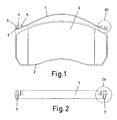
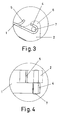
- the invention refers to improvements which affect the arrangement of the installation of a strip (1) on the pads of disc brakes, which same conventionally comprise a metal support plate (2), which may be die-cut or cast, and a lining (3) formed by a block of friction material fixed on one of the faces of the support plate (2).
- the strip (1) is constituted in a known manner by a bowed element arranged on the upper edge of the support plate (2) of the brake pad, pressing with its ends on the said edge of the support plate (2), whilst the central part remains free, in order to establish by means of the said central part of the strip (1) an elastic support in the installation of the brake pad, such that by means of the bearing pressure the ends of the said strip (1) exert a force on the support plate (2), preventing the vibration of the brake pad.
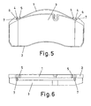
- the ends of the strip (1) are defined by one half of the width bent (4) in the form of a hook, whilst the other half of the width has the form of an upwardly-curved front edge (5).
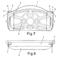
- the support plate (2) of the brake pad in turn has the form of shapes (6) like merlons (i.e. raised portions defining a side which, in the examples shown, is concave), in the end regions of the upper edge, whilst perpendicularly on the face on which the lining (3) is located, in the regions adjacent to the said ends of the upper edge, the plate (2) referred to incorporates rods (7).
- the said rods (7) may form part of the plate (2) in one embodiment of its construction, but equally, without this altering their function, they may be incorporated in an accessory manner, by any known fastening means, for example driven in under pressure, threaded coupling, riveted, weld, etc.
- the strip (1) is formed with a distance between the end bends (4) coinciding with the distance separating the rods (7) on the support plate (2) of the brake pad and with a distance between the curved edges (5) of the other half of the ends somewhat less than the distance between the internal edges of the merlons (6) of the edge of the plate (2).
- the installation of the strip (1) on the brake pad may be executed by means of the simple insertion of the end bends (4) of the same over the rods (7) of the support plate (2) of the brake pad, until abutting against the corresponding face of the said plate (2), in that position the curved edges (5) face the merlons (6) at a given distance from the same, as may be particularly observed in figures 1 and 3.
- the installation of the strip (1) does not thus present any difficulty, as it is not necessary to flex the said strip (1) in order to fix it, as this occurs simply by engaging the bends (4) over the rods (7) and the pressure of the parts which correspond to the curved edges (5) on the upper edge of the support plate (2).
- the strip (1) does not require to be flexed, the risk of accidents is also avoided in the execution of its installation and removal, given that the absence of tension prevents the strip (1) from escaping and springing off during the manipulations.
- the strip (1) permits the establishment of an elastic pressure support on the brake pad in its installation of application, because as a result of the central part of the strip (1) being constrained by pressure, the ends of the same exert pressure on the upper edge of the support plate (2) by means of the half of the width which corresponds to the curved edges (5) and on the rods (7) by means of the bends (4).
- the strip (1) On exerting the said pressure, the strip (1) extends displacing its ends on the corresponding supports, the said displacement being restricted by the curved edges (5), given that when these latter reach the merlons (6) they abut against them preventing the continuation of the displacement.
- the bends (4) are prevented from being able to become disengaged from the rods (7) and that the deformation of the strip (1) with respect to its static form may become excessive with the risk of deterioration.
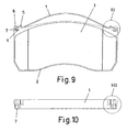
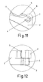
- the bends (4) of the ends of the strip (1) may be made by means of bending upwards the corresponding halves of the ends of the strip (1), as in figures 1 to 8, or by bending downwards, as in figures 9 to 12, as in both cases the effect of the pressure of the strip (1) on the brake pad is similar, when the strip (1) is constrained by a pressure on its central region.
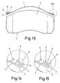
- the hooks of the ends of the rod (1) for their installation with respect to the rods (7) of the support plate (2) of the brake pad may be defined in the form of a slot (8) made in a portion of flange (9) bent perpendicularly on the edge of the corresponding halves of the ends of the strip (1), as shown in figure 13.
- the slots (8) for engaging the rods (7) may have, in this case, an open configuration, as in figure 14, or a closed configuration, as in figure 15, in both cases equally complying with the object of the invention.
- At least one of the rods (7) shall have an expansion at its free end in order to act as retention preventing the strip (1) coming off the installation by itself.
- the said limiting expansion in order to retain the strip (1) in the installation may be a broadening in the form of a head of the rod itself (7), or accessory elements incorporated in a supplementary and disassemblable manner, such as nuts, clips, etc.
- the object of the invention is applicable to disc brakes of any kind, both of industrial vehicles and of automobiles, and of any machine which possesses brakes of this type, in which the corresponding brake pads due to the free play necessary in the installation may suffer vibrations which it is desired to suppress.
Landscapes
- Engineering & Computer Science (AREA)
- General Engineering & Computer Science (AREA)
- Mechanical Engineering (AREA)
- Braking Arrangements (AREA)
Abstract
Description
Claims (6)
- Disc brake pad device, comprising a brake pad which comprises a metal support plate (2) and a lining (3) of friction material, and a strip (1) formed by a longitudinally-bowed leaf element which is incorporated on the upper edge of the support plate (2), characterised in that the ends of the strip (1) have the form in one half of their width of bends (4) in the manner of hooks, whilst the other half of their width is defined with an upwardly-curved front edge (5); the support plate (2) of the brake pad, in the end regions adjacent to the upper edge of the face on which the lining (3) is located, incorporating perpendicular rods (7), with respect to which the end bends of the strip (1) are engaged, whilst the upper edge of the said support plate (2) has in the end regions the form of shapes (6) in the manner of merlons, facing which at a given distance above the upper edge referred to are the curved edges (5) of the other half of the width of the ends of the strip (1).
- Disc brake pad device according to claim 1, characterised in that the curved edges (5) of the ends of the strip (1) are at a distance from the merlons (6) of the support plate (2), in order to abut against them at a distance less than that which the bends (4) permit on the rods (7) when the strip (1) extends constrained by a central pressure on it.
- Disc brake pad device according to claim 1 or 2, characterised in that the rods (7) may be integral with the support plate (2) or be incorporated in an accessory manner by any fastening means.
- Disc brake pad device according to any one of claims 1 to 3, characterised in that at least one of the rods (7) has at its free end a broadening, integral or accessory, in order to retain the strip (1).
- Disc brake pad device according to any one of claims 1 to 4, characterised in that the bends (4) of the ends of the strip (1) may be formed indifferently by bending upwards or downwards.
- Disc brake pad device according to any one of claims 1 to 5, characterised in that the hooks of the ends of the strip (1) for their installation with respect to the rods (7) of the support plate (2) are constituted in the form of slots (8) made in portions of flange (9) perpendicularly bent on the edges of the corresponding halves of the ends of the strip (1), said slots (8) being open or closed.
Priority Applications (1)
| Application Number | Priority Date | Filing Date | Title |
|---|---|---|---|
| EP08101789A EP1918604A1 (en) | 2003-01-30 | 2004-01-28 | Improvements in disc brake pads |
Applications Claiming Priority (2)
| Application Number | Priority Date | Filing Date | Title |
|---|---|---|---|
| ES200300238 | 2003-01-30 | ||
| ES200300238A ES2233163B1 (en) | 2003-01-30 | 2003-01-30 | IMPROVEMENTS INTRODUCED IN THE DISK BRAKE PADS. |
Related Child Applications (2)
| Application Number | Title | Priority Date | Filing Date |
|---|---|---|---|
| EP08101789A Division EP1918604A1 (en) | 2003-01-30 | 2004-01-28 | Improvements in disc brake pads |
| EP08101789.9 Division-Into | 2008-02-20 |
Publications (3)
| Publication Number | Publication Date |
|---|---|
| EP1452765A2 true EP1452765A2 (en) | 2004-09-01 |
| EP1452765A3 EP1452765A3 (en) | 2004-09-08 |
| EP1452765B1 EP1452765B1 (en) | 2011-08-31 |
Family
ID=32749104
Family Applications (2)
| Application Number | Title | Priority Date | Filing Date |
|---|---|---|---|
| EP08101789A Withdrawn EP1918604A1 (en) | 2003-01-30 | 2004-01-28 | Improvements in disc brake pads |
| EP04290216A Expired - Lifetime EP1452765B1 (en) | 2003-01-30 | 2004-01-28 | Improvements in disc brake pads |
Family Applications Before (1)
| Application Number | Title | Priority Date | Filing Date |
|---|---|---|---|
| EP08101789A Withdrawn EP1918604A1 (en) | 2003-01-30 | 2004-01-28 | Improvements in disc brake pads |
Country Status (4)
| Country | Link |
|---|---|
| EP (2) | EP1918604A1 (en) |
| AT (1) | ATE522738T1 (en) |
| ES (1) | ES2233163B1 (en) |
| PL (1) | PL209662B1 (en) |
Cited By (6)
| Publication number | Priority date | Publication date | Assignee | Title |
|---|---|---|---|---|
| EP1698795A1 (en) | 2005-03-04 | 2006-09-06 | Emmerre s.r.l. | Fixing device for disk brake pads |
| DE102005038298A1 (en) * | 2005-08-12 | 2007-02-15 | Federal-Mogul Friction Products Gmbh | Brake pad with integrated hold-down spring and method for the production of the brake pad |
| EP2105627A1 (en) * | 2008-03-26 | 2009-09-30 | Lumag Sp. z o.o | Brake pad with retaining spring |
| EP2048403A3 (en) * | 2007-08-14 | 2011-01-05 | KNORR-BREMSE Systeme für Nutzfahrzeuge GmbH | Brake pad for a disc brake |
| WO2014086474A1 (en) * | 2012-12-05 | 2014-06-12 | Wabco Radbremsen Gmbh | Disc brake and a hold-down spring for such a disc brake |
| DE102017008809A1 (en) * | 2017-09-20 | 2019-03-21 | Wabco Europe Bvba | Belaghaltesystem for a disc brake |
Family Cites Families (10)
| Publication number | Priority date | Publication date | Assignee | Title |
|---|---|---|---|---|
| GB1535720A (en) | 1974-12-24 | 1978-12-13 | Girling Ltd | Friction pad assemblies for sliding caliper disc brakes |
| FR2461161A1 (en) | 1979-07-06 | 1981-01-30 | Ferodo Sa | Automobile disc brake pad - has lining on back plate with corner lugs which locate ends of curved blade packing spring |
| FR2517399B1 (en) * | 1981-11-30 | 1986-12-05 | Dba | DISC BRAKE AND PAD FOR SUCH A BRAKE |
| GB2185079B (en) * | 1986-01-04 | 1989-10-25 | Automotive Products Plc | Disc brakes |
| DE4020287A1 (en) | 1990-06-26 | 1992-01-02 | Knorr Bremse Ag | PAD MOUNTING IN DISC BRAKES FOR ROAD VEHICLES, IN PARTICULAR COMMERCIAL VEHICLES |
| DE4128090C2 (en) * | 1991-08-24 | 1998-08-20 | Teves Gmbh Alfred | Spreading spring with additional spring arm for a disc brake, especially a fixed-caliper brake |
| GB9207985D0 (en) * | 1992-04-10 | 1992-05-27 | Lucas Ind Plc | Pad assembly for a disc brake |
| GB9618011D0 (en) * | 1996-08-29 | 1996-10-09 | T & N Technology Ltd | Friction pad assembly |
| US5875873A (en) | 1997-05-05 | 1999-03-02 | Meritor Heavy Vehicle Systems, Llc | Air disc brake anti-rattle design |
| DE10026547C2 (en) * | 2000-05-27 | 2003-10-02 | Hermann Peters Gmbh & Co | Brake pad for a disc brake |
-
2003
- 2003-01-30 ES ES200300238A patent/ES2233163B1/en not_active Expired - Fee Related
-
2004
- 2004-01-28 EP EP08101789A patent/EP1918604A1/en not_active Withdrawn
- 2004-01-28 AT AT04290216T patent/ATE522738T1/en not_active IP Right Cessation
- 2004-01-28 EP EP04290216A patent/EP1452765B1/en not_active Expired - Lifetime
- 2004-01-29 PL PL364636A patent/PL209662B1/en not_active IP Right Cessation
Cited By (8)
| Publication number | Priority date | Publication date | Assignee | Title |
|---|---|---|---|---|
| EP1698795A1 (en) | 2005-03-04 | 2006-09-06 | Emmerre s.r.l. | Fixing device for disk brake pads |
| DE102005038298A1 (en) * | 2005-08-12 | 2007-02-15 | Federal-Mogul Friction Products Gmbh | Brake pad with integrated hold-down spring and method for the production of the brake pad |
| EP2048403A3 (en) * | 2007-08-14 | 2011-01-05 | KNORR-BREMSE Systeme für Nutzfahrzeuge GmbH | Brake pad for a disc brake |
| EP2105627A1 (en) * | 2008-03-26 | 2009-09-30 | Lumag Sp. z o.o | Brake pad with retaining spring |
| WO2014086474A1 (en) * | 2012-12-05 | 2014-06-12 | Wabco Radbremsen Gmbh | Disc brake and a hold-down spring for such a disc brake |
| JP2015537174A (en) * | 2012-12-05 | 2015-12-24 | ワブコ ラドブレムセン ゲゼルシャフト ミット ベシュレンクテル ハフツング | Disc brake and presser spring for such disc brake |
| RU2655790C2 (en) * | 2012-12-05 | 2018-05-29 | Вабко Радбремзен Гмбх | Disk brake and hold-down spring of such a disk brake |
| DE102017008809A1 (en) * | 2017-09-20 | 2019-03-21 | Wabco Europe Bvba | Belaghaltesystem for a disc brake |
Also Published As
| Publication number | Publication date |
|---|---|
| ES2233163B1 (en) | 2006-02-01 |
| EP1918604A1 (en) | 2008-05-07 |
| PL364636A1 (en) | 2004-08-09 |
| EP1452765B1 (en) | 2011-08-31 |
| ATE522738T1 (en) | 2011-09-15 |
| EP1452765A3 (en) | 2004-09-08 |
| ES2233163A1 (en) | 2005-06-01 |
| PL209662B1 (en) | 2011-10-31 |
Similar Documents
| Publication | Publication Date | Title |
|---|---|---|
| CN100473572C (en) | Method for arranging brake block into brake caliper | |
| CN100378364C (en) | Guide springs for friction parts and disc brakes fitted with at least one such spring | |
| US8220595B2 (en) | Brake pad for a disc brake | |
| JP4698147B2 (en) | Disc brake assembly | |
| US6957724B2 (en) | Vehicle disk brake | |
| HU213483B (en) | Brake-insert support for the disc brakes of road vehicles particularly lorries | |
| CN103797264A (en) | Disc brakes and brake linings for motor vehicles | |
| US20170299004A1 (en) | Guide Means For A Brake Lining Arrangement Of A Disc Brake, And Disc Brake | |
| EP1452765B1 (en) | Improvements in disc brake pads | |
| CN109073002A (en) | Friction lining assemblies for partially lined disc brakes of motor vehicles | |
| GB2132292A (en) | Disc brake | |
| CN1045651C (en) | Disk brake | |
| JPS6054531B2 (en) | disc brake | |
| US4784242A (en) | Pad for a disc brake and disc brake equipped with such pads | |
| EP3810953B2 (en) | Spring for friction pads in a disc brake caliper | |
| CN115087813B (en) | Brake pad retainer system, brake pad and vehicle | |
| CN112313427B (en) | Springs for friction pads in calipers of disc brakes | |
| CN117441069A (en) | Band springs and band spring and brake pad assemblies | |
| US11746840B2 (en) | Retention system for shim on backplate of brake pad assembly | |
| CN115929817A (en) | Brake clip and apparatus for a disc brake assembly | |
| JP4773021B2 (en) | Retainer clip for brake pad support pin | |
| EP0094736B1 (en) | Disc brakes | |
| CN116829848A (en) | Band spring used to move the brake pad back and forth on the caliper | |
| CN117795224A (en) | Disc brakes for commercial vehicles and brake linings for disc brakes | |
| JPH0681968B2 (en) | Disc brakes for vehicles |
Legal Events
| Date | Code | Title | Description |
|---|---|---|---|
| PUAI | Public reference made under article 153(3) epc to a published international application that has entered the european phase |
Free format text: ORIGINAL CODE: 0009012 |
|
| PUAL | Search report despatched |
Free format text: ORIGINAL CODE: 0009013 |
|
| AK | Designated contracting states |
Kind code of ref document: A2 Designated state(s): AT BE BG CH CY CZ DE DK EE ES FI FR GB GR HU IE IT LI LU MC NL PT RO SE SI SK TR |
|
| AX | Request for extension of the european patent |
Extension state: AL LT LV MK |
|
| AK | Designated contracting states |
Kind code of ref document: A3 Designated state(s): AT BE BG CH CY CZ DE DK EE ES FI FR GB GR HU IE IT LI LU MC NL PT RO SE SI SK TR |
|
| AX | Request for extension of the european patent |
Extension state: AL LT LV MK |
|
| 17P | Request for examination filed |
Effective date: 20050303 |
|
| AKX | Designation fees paid |
Designated state(s): AT BE BG CH CY CZ DE DK EE ES FI FR GB GR HU IE IT LI LU MC NL PT RO SE SI SK TR |
|
| R17P | Request for examination filed (corrected) |
Effective date: 20050303 |
|
| 17Q | First examination report despatched |
Effective date: 20060912 |
|
| GRAP | Despatch of communication of intention to grant a patent |
Free format text: ORIGINAL CODE: EPIDOSNIGR1 |
|
| GRAS | Grant fee paid |
Free format text: ORIGINAL CODE: EPIDOSNIGR3 |
|
| GRAA | (expected) grant |
Free format text: ORIGINAL CODE: 0009210 |
|
| AK | Designated contracting states |
Kind code of ref document: B1 Designated state(s): AT BE BG CH CY CZ DE DK EE ES FI FR GB GR HU IE IT LI LU MC NL PT RO SE SI SK TR |
|
| REG | Reference to a national code |
Ref country code: GB Ref legal event code: FG4D Ref country code: CH Ref legal event code: EP |
|
| REG | Reference to a national code |
Ref country code: IE Ref legal event code: FG4D |
|
| REG | Reference to a national code |
Ref country code: DE Ref legal event code: R096 Ref document number: 602004034194 Country of ref document: DE Effective date: 20111110 |
|
| REG | Reference to a national code |
Ref country code: NL Ref legal event code: VDEP Effective date: 20110831 |
|
| PG25 | Lapsed in a contracting state [announced via postgrant information from national office to epo] |
Ref country code: FI Free format text: LAPSE BECAUSE OF FAILURE TO SUBMIT A TRANSLATION OF THE DESCRIPTION OR TO PAY THE FEE WITHIN THE PRESCRIBED TIME-LIMIT Effective date: 20110831 Ref country code: NL Free format text: LAPSE BECAUSE OF FAILURE TO SUBMIT A TRANSLATION OF THE DESCRIPTION OR TO PAY THE FEE WITHIN THE PRESCRIBED TIME-LIMIT Effective date: 20110831 Ref country code: SE Free format text: LAPSE BECAUSE OF FAILURE TO SUBMIT A TRANSLATION OF THE DESCRIPTION OR TO PAY THE FEE WITHIN THE PRESCRIBED TIME-LIMIT Effective date: 20110831 |
|
| REG | Reference to a national code |
Ref country code: AT Ref legal event code: MK05 Ref document number: 522738 Country of ref document: AT Kind code of ref document: T Effective date: 20110831 |
|
| PG25 | Lapsed in a contracting state [announced via postgrant information from national office to epo] |
Ref country code: SI Free format text: LAPSE BECAUSE OF FAILURE TO SUBMIT A TRANSLATION OF THE DESCRIPTION OR TO PAY THE FEE WITHIN THE PRESCRIBED TIME-LIMIT Effective date: 20110831 Ref country code: CY Free format text: LAPSE BECAUSE OF FAILURE TO SUBMIT A TRANSLATION OF THE DESCRIPTION OR TO PAY THE FEE WITHIN THE PRESCRIBED TIME-LIMIT Effective date: 20110831 Ref country code: AT Free format text: LAPSE BECAUSE OF FAILURE TO SUBMIT A TRANSLATION OF THE DESCRIPTION OR TO PAY THE FEE WITHIN THE PRESCRIBED TIME-LIMIT Effective date: 20110831 Ref country code: GR Free format text: LAPSE BECAUSE OF FAILURE TO SUBMIT A TRANSLATION OF THE DESCRIPTION OR TO PAY THE FEE WITHIN THE PRESCRIBED TIME-LIMIT Effective date: 20111201 |
|
| PG25 | Lapsed in a contracting state [announced via postgrant information from national office to epo] |
Ref country code: BE Free format text: LAPSE BECAUSE OF FAILURE TO SUBMIT A TRANSLATION OF THE DESCRIPTION OR TO PAY THE FEE WITHIN THE PRESCRIBED TIME-LIMIT Effective date: 20110831 |
|
| PG25 | Lapsed in a contracting state [announced via postgrant information from national office to epo] |
Ref country code: CZ Free format text: LAPSE BECAUSE OF FAILURE TO SUBMIT A TRANSLATION OF THE DESCRIPTION OR TO PAY THE FEE WITHIN THE PRESCRIBED TIME-LIMIT Effective date: 20110831 Ref country code: SK Free format text: LAPSE BECAUSE OF FAILURE TO SUBMIT A TRANSLATION OF THE DESCRIPTION OR TO PAY THE FEE WITHIN THE PRESCRIBED TIME-LIMIT Effective date: 20110831 |
|
| PG25 | Lapsed in a contracting state [announced via postgrant information from national office to epo] |
Ref country code: IT Free format text: LAPSE BECAUSE OF FAILURE TO SUBMIT A TRANSLATION OF THE DESCRIPTION OR TO PAY THE FEE WITHIN THE PRESCRIBED TIME-LIMIT Effective date: 20110831 Ref country code: RO Free format text: LAPSE BECAUSE OF FAILURE TO SUBMIT A TRANSLATION OF THE DESCRIPTION OR TO PAY THE FEE WITHIN THE PRESCRIBED TIME-LIMIT Effective date: 20110831 Ref country code: PT Free format text: LAPSE BECAUSE OF FAILURE TO SUBMIT A TRANSLATION OF THE DESCRIPTION OR TO PAY THE FEE WITHIN THE PRESCRIBED TIME-LIMIT Effective date: 20120102 Ref country code: EE Free format text: LAPSE BECAUSE OF FAILURE TO SUBMIT A TRANSLATION OF THE DESCRIPTION OR TO PAY THE FEE WITHIN THE PRESCRIBED TIME-LIMIT Effective date: 20110831 |
|
| PLBI | Opposition filed |
Free format text: ORIGINAL CODE: 0009260 |
|
| PG25 | Lapsed in a contracting state [announced via postgrant information from national office to epo] |
Ref country code: DK Free format text: LAPSE BECAUSE OF FAILURE TO SUBMIT A TRANSLATION OF THE DESCRIPTION OR TO PAY THE FEE WITHIN THE PRESCRIBED TIME-LIMIT Effective date: 20110831 |
|
| 26 | Opposition filed |
Opponent name: VRI-VERBAND DER REIBBELAGINDUSTRIE E.V. Effective date: 20120525 |
|
| PLAX | Notice of opposition and request to file observation + time limit sent |
Free format text: ORIGINAL CODE: EPIDOSNOBS2 |
|
| REG | Reference to a national code |
Ref country code: DE Ref legal event code: R026 Ref document number: 602004034194 Country of ref document: DE Effective date: 20120525 |
|
| PG25 | Lapsed in a contracting state [announced via postgrant information from national office to epo] |
Ref country code: MC Free format text: LAPSE BECAUSE OF NON-PAYMENT OF DUE FEES Effective date: 20120131 |
|
| REG | Reference to a national code |
Ref country code: CH Ref legal event code: PL |
|
| GBPC | Gb: european patent ceased through non-payment of renewal fee |
Effective date: 20120128 |
|
| REG | Reference to a national code |
Ref country code: FR Ref legal event code: ST Effective date: 20120928 |
|
| REG | Reference to a national code |
Ref country code: IE Ref legal event code: MM4A |
|
| PG25 | Lapsed in a contracting state [announced via postgrant information from national office to epo] |
Ref country code: GB Free format text: LAPSE BECAUSE OF NON-PAYMENT OF DUE FEES Effective date: 20120128 Ref country code: DE Free format text: LAPSE BECAUSE OF NON-PAYMENT OF DUE FEES Effective date: 20120801 Ref country code: LI Free format text: LAPSE BECAUSE OF NON-PAYMENT OF DUE FEES Effective date: 20120131 Ref country code: CH Free format text: LAPSE BECAUSE OF NON-PAYMENT OF DUE FEES Effective date: 20120131 |
|
| REG | Reference to a national code |
Ref country code: DE Ref legal event code: R119 Ref document number: 602004034194 Country of ref document: DE Effective date: 20120801 |
|
| PG25 | Lapsed in a contracting state [announced via postgrant information from national office to epo] |
Ref country code: FR Free format text: LAPSE BECAUSE OF NON-PAYMENT OF DUE FEES Effective date: 20120131 |
|
| PG25 | Lapsed in a contracting state [announced via postgrant information from national office to epo] |
Ref country code: IE Free format text: LAPSE BECAUSE OF NON-PAYMENT OF DUE FEES Effective date: 20120128 |
|
| PG25 | Lapsed in a contracting state [announced via postgrant information from national office to epo] |
Ref country code: ES Free format text: LAPSE BECAUSE OF FAILURE TO SUBMIT A TRANSLATION OF THE DESCRIPTION OR TO PAY THE FEE WITHIN THE PRESCRIBED TIME-LIMIT Effective date: 20111211 |
|
| PG25 | Lapsed in a contracting state [announced via postgrant information from national office to epo] |
Ref country code: BG Free format text: LAPSE BECAUSE OF FAILURE TO SUBMIT A TRANSLATION OF THE DESCRIPTION OR TO PAY THE FEE WITHIN THE PRESCRIBED TIME-LIMIT Effective date: 20111130 |
|
| PG25 | Lapsed in a contracting state [announced via postgrant information from national office to epo] |
Ref country code: TR Free format text: LAPSE BECAUSE OF FAILURE TO SUBMIT A TRANSLATION OF THE DESCRIPTION OR TO PAY THE FEE WITHIN THE PRESCRIBED TIME-LIMIT Effective date: 20110831 |
|
| PG25 | Lapsed in a contracting state [announced via postgrant information from national office to epo] |
Ref country code: LU Free format text: LAPSE BECAUSE OF NON-PAYMENT OF DUE FEES Effective date: 20120128 |
|
| PG25 | Lapsed in a contracting state [announced via postgrant information from national office to epo] |
Ref country code: HU Free format text: LAPSE BECAUSE OF FAILURE TO SUBMIT A TRANSLATION OF THE DESCRIPTION OR TO PAY THE FEE WITHIN THE PRESCRIBED TIME-LIMIT Effective date: 20040128 |
|
| PLBD | Termination of opposition procedure: decision despatched |
Free format text: ORIGINAL CODE: EPIDOSNOPC1 |
|
| PLBM | Termination of opposition procedure: date of legal effect published |
Free format text: ORIGINAL CODE: 0009276 |
|
| STAA | Information on the status of an ep patent application or granted ep patent |
Free format text: STATUS: OPPOSITION PROCEDURE CLOSED |
|
| 27C | Opposition proceedings terminated |
Effective date: 20141109 |