EP1457601B1 - Vorrichtung und Verfahren zum abschnittsweisen Herstellen eines Stahlbeton- oder Spannbetontragwerks - Google Patents
Vorrichtung und Verfahren zum abschnittsweisen Herstellen eines Stahlbeton- oder Spannbetontragwerks Download PDFInfo
- Publication number
- EP1457601B1 EP1457601B1 EP03005352A EP03005352A EP1457601B1 EP 1457601 B1 EP1457601 B1 EP 1457601B1 EP 03005352 A EP03005352 A EP 03005352A EP 03005352 A EP03005352 A EP 03005352A EP 1457601 B1 EP1457601 B1 EP 1457601B1
- Authority
- EP
- European Patent Office
- Prior art keywords
- supporting framework
- feed
- section
- formwork
- new
- Prior art date
- Legal status (The legal status is an assumption and is not a legal conclusion. Google has not performed a legal analysis and makes no representation as to the accuracy of the status listed.)
- Expired - Lifetime
Links
- 238000000034 method Methods 0.000 title claims abstract description 27
- 239000011150 reinforced concrete Substances 0.000 title claims abstract description 9
- 239000011513 prestressed concrete Substances 0.000 title claims description 13
- 238000010276 construction Methods 0.000 claims abstract description 63
- 238000009415 formwork Methods 0.000 claims description 70
- 238000004519 manufacturing process Methods 0.000 claims description 14
- 238000004873 anchoring Methods 0.000 claims description 8
- 238000009416 shuttering Methods 0.000 abstract description 17
- 230000000750 progressive effect Effects 0.000 abstract 1
- 238000005452 bending Methods 0.000 description 8
- 239000004567 concrete Substances 0.000 description 8
- 230000002787 reinforcement Effects 0.000 description 6
- 229910000831 Steel Inorganic materials 0.000 description 5
- 238000011161 development Methods 0.000 description 5
- 239000010959 steel Substances 0.000 description 5
- 239000000969 carrier Substances 0.000 description 4
- 230000006835 compression Effects 0.000 description 4
- 238000007906 compression Methods 0.000 description 4
- 230000005540 biological transmission Effects 0.000 description 2
- 238000013461 design Methods 0.000 description 2
- 238000003780 insertion Methods 0.000 description 2
- 230000037431 insertion Effects 0.000 description 2
- 230000003014 reinforcing effect Effects 0.000 description 2
- 238000012546 transfer Methods 0.000 description 2
- 210000003323 beak Anatomy 0.000 description 1
- 239000011230 binding agent Substances 0.000 description 1
- 238000005253 cladding Methods 0.000 description 1
- 230000009194 climbing Effects 0.000 description 1
- 239000002131 composite material Substances 0.000 description 1
- 238000011065 in-situ storage Methods 0.000 description 1
- 239000011178 precast concrete Substances 0.000 description 1
- 238000007493 shaping process Methods 0.000 description 1
- 239000007787 solid Substances 0.000 description 1
- 238000003860 storage Methods 0.000 description 1
- 239000000725 suspension Substances 0.000 description 1
Images






Classifications
-
- E—FIXED CONSTRUCTIONS
- E01—CONSTRUCTION OF ROADS, RAILWAYS, OR BRIDGES
- E01D—CONSTRUCTION OF BRIDGES, ELEVATED ROADWAYS OR VIADUCTS; ASSEMBLY OF BRIDGES
- E01D21/00—Methods or apparatus specially adapted for erecting or assembling bridges
- E01D21/10—Cantilevered erection
- E01D21/105—Balanced cantilevered erection
Definitions
- the present invention relates to a device and a Method for producing in sections a reinforced concrete or Prestressed concrete structure in cantilever construction.
- Under reinforced concrete or Prestressed concrete structures also become supporting structures understood that in composite construction, for example, with additional steel profiles or elements or the like, getting produced.
- the spanning a free space such as bridges, Bows, binders or the like
- spanning a free space such as bridges, Bows, binders or the like
- construction methods and devices known.
- the so-called Taktschiebe compiler, the Bogenklapphabilit and the Free cantilever method each with special Formwork systems, known.
- DE-AS 12 91 348 discloses a method and a device for producing in sections Bridge superstructures in cantilever construction.
- a framework Trüstrich used with extremely large dimensions, whose Length is designed such that it the span of the later structure, similar to one Formwork.
- the carrier is used for storage and Advancing a formwork, with the help of which successive Structural sections are concreted.
- the entire burden of Formwork as well as the introduced fresh concrete must of the Jostani added and in the already manufactured Building sections are forwarded. Because of the high Load, in particular bending load, as well as the large Span of the frame bearer this must be very strong be executed, which makes this complex and expensive and further complicates his handling.
- the DE 36 20 587 C1 discloses a method and a Device for sectionally producing Bridge superstructures in cantilever construction.
- the device has a cantilever cantilever and a formwork, however has no bottom formwork, as the bottom of the structure by a Prefabricated part is provided.
- the structure floor is in the the previous construction phase anchored before the rest Parts of the new construction section are produced.
- the method has the disadvantage that it is neither for In-situ concrete still for any cross-sectional shapes, such as for example, solid sections, is suitable.
- the reverse voltages represent lost components, what makes the process uneconomical.
- the must Krag mecanic also comparatively strong executed be to the weight of the formwork as well as the Heavyweight precast concrete before re-tensioning take.
- DE 25 55 311 A discloses a device according to the Preamble of claim 1.
- the present invention is based on the idea that Load transfer in a formwork device such Optimize that stress to a great extent about tensile and / or compressive forces, and not just about Bending moments and shear forces in the already completed Structural sections is derived.
- This is according to the invention realized in that the carrying device in the region of new construction section by means of at least one train and / or Strut with at least one completed Construction section is connected.
- a device for sections Manufacture of a steel or prestressed concrete structure not just a simple design owns, but also has a number of other advantages.
- the load, by means of bulky bending beam in already finished Building sections is to be reduced to a minimum. Therefore, much more filigree components for the Carrying device can be used.
- the Carrying device only the weight of the first Shuttering during their advance into a new Ablate structural section and therefore can accordingly be carried out easily and inexpensively.
- the considerable weight of the structural sections, in particular of the concrete to be introduced, directly through the at least one tension and / or compression strut in the previous structural sections removed what the remaining components of the device according to the invention extremely relieved.
- the low weight of the invention Device itself is extremely advantageous. It is to note that the structure to be produced by a Freivorbaukonstrument is loaded cantilever, so that in the structure undergoes high bending moments, which as its own Load case to be calculated and proven. These Stress is due to the low weight of the construction according to the invention significantly reduced, which also makes the structure itself more economical. Not least This is also the stress of a Auxiliary construction, such as the back tension of a cantilever arch, reduced.
- the device according to the invention allows also a fast construction progress.
- the device receives an improved Adaptability to variable structural geometries, such as for example, with arches with variable cross-section.
- the at least one Tensile and / or compression strut is biased and preferred opposite to a direction in which the structural sections follow each other, is inclined. This will at the same time an optimal power transmission between the first Shuttering device and previous structural section ensured.
- the at least one train and / or Strut in marginal areas of the structural sections is arranged.
- the Structural sections created a generous working space, which facilitates the work and in particular the insertion prefabricated reinforcement baskets allows what the Construction progress significantly accelerated.
- the at least one tension and / or compression strut is arranged in the side walls of the structural sections.
- the support device a feed carrier, with the at least one previous structural section is connected.
- the first formwork device displaceable by means of at least one adjustable spindle is mounted along the feed carrier, wherein the at least one spindle particularly preferably outside the Cross-section of the new structural section is arranged.
- the at least one adjustable spindle not only allows a stable holding of the first formwork device during of the feed, but also a precise set up same in the new structural section. Furthermore allows the at least one adjustable spindle targeted unloading of the carrying device as soon as the first Formwork device in the at least one preceding Structural section is biased back.
- the arrangement of at least one adjustable spindle outside the Cross-section of the new structural section also allows that prefabricated reinforcing baskets as a whole in the new Tragtechniksabites can be inserted, which is the Construction progress significantly accelerated.
- box girder structures or similar complex cross sections are according to another Objective of the present invention provided that they further comprises a second formwork device, wherein Preferably, the first formwork device for forming a Outer contour and the second formwork device for formwork an inner contour of the structure is designed. This will also working in different ways simultaneously Structural sections allows.
- the second Formwork device is connected to the support device, in particular by means of at least one pressure strut. hereby contributes to the second formwork on the one hand Relief of the support device, on the other hand, a Joint advancement and anchoring of both institutions enables what simplifies the construction process.
- a second feed device with the carrying device and / or the second Formwork device is connectable.
- the first and / or second Feed device at least during the feed to the anchored at least one previous structural section is. It has the use of at least one console, the attached to a preceding structural section, as proved particularly advantageous.
- the first formwork device hangs when advancing in the new structural section freely over the to be spanned Room. Therefore, it is according to an embodiment of the present Invention preferred that the first formwork device at least during the feed on the console of the first Feed device is slidably mounted. That's it with a view to minimizing the feed forces preferred that the console a roll or the like identifies, on which the first formwork device is guided.
- An advantageous embodiment of the present invention is characterized by the fact that the first and / or second Feed device has a drive.
- the drive in the pilgrim step method works and / or has a hydraulic cylinder, since This makes it extremely compact, lighter and cheaper Drive provided with sufficiently high feed force becomes.
- the first and / or second feed device is a substantially longitudinally extending element along which the drive is movable and / or which is movable along the drive. That's it particularly preferred that the reciprocal method of Drive and essentially in the longitudinal direction extending element in the vocational step method.
- the first formwork device at least one Shell element, along the first formwork device is displaceable.
- the present invention provides a method for in sections producing a reinforced concrete or A prestressed concrete structure according to claim 16 ready, which in particular the re-tensioning of at least a part of a first formwork device operating in the area of a new one Located in a preceding section Structural section by means of at least one train and / or Pressure strut provides. That way, the ones above described advantages of the device according to the invention, in particular a rapid construction progress and a corresponding shortened construction time, achieved.
- This concept is developed according to the invention by that advancing the first formwork device in the new construction phase already before the completion of the previous construction phase. This is the Do not work limited to a section, but you can take place in parallel in at least two structural sections, which considerably shortens the construction time.
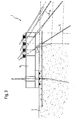
- Figures 1 and 2 each schematically show a Side view or a sectional view of a preferred Embodiment of the device 1 according to the invention for in sections producing a reinforced concrete or Prestressed concrete structure 2 in cantilever construction.
- the device 1 comprises a first formwork device in the form of a ceremoniesschalwagens10, each for peeling a new Structural section n + 1 is used.
- the outer formwork carriage 10 is with already finished structural sections in connectable to different positions, for example by means of Anchors or the like, and is by means of a first Feed device 12 each from a preceding Structural section n to the new structural section n + 1 traversable.
- the outer shell cart 10 is in the present Embodiment formed by a truss structure, the Shuttering elements 10 'in the form of formwork panels or The like contributes to the shaping of the prestressed concrete structure serve.
- the first shuttering device or outer shuttering cart 10 is in the state shown in Fig. 1 by means of tie rods 14th connected to the preceding structural section n.
- tie rods 14th connected to the preceding structural section n.
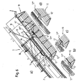
- the tie rods 14 with both the outer shell carriage 10 than also articulated with the preceding structural section n connected, wherein the articulated connection with the previous structural section n in the present Embodiment by means of anchoring profiles 16 is realized, which are shown in more detail in Fig. 3.
- anchoring profiles 16 a ball-joint end suspension of the tension struts 14, so that the tie rods 14 are arranged at arbitrary angles can be and harmful bending moments in the tension struts 14 avoided.
- the tie rods 14 are opposite to the direction in which the Follow structural sections n, n + 1 at a time, inclined and are each prestressed by means of end nuts or the like, around between the outer shell carriage 10 and the previous one Structural section n transmitted force or the mutual Regulate alignment.
- the tie rods are 14 viewed in section in marginal areas of the respective Structural sections n, n + 1, ... arranged. More precisely are in the present embodiment, the tie rods 14 in positioned the side walls of the bridge box and hollow when concreting sidewalls from concrete locked in. However, it should be noted that the location of the Pull struts 14 in principle is arbitrary. It is beyond that Not required according to the invention that the tie rods 14 in the structure are embedded in concrete, which, for example, by Cladding tubes or the like could be avoided.
- tie rods 14 in principle also partially or completely by inclined pressure struts can be replaced, if necessary, using appropriate Auxiliary elements, supports or the like.
- the device 1 comprises a support device 20, which in the present embodiment two Feed carrier 22 which, for example, the shape of I-wearers own and directly or indirectly one of the previous, at least partially completed Support the structural sections.
- the device 1 comprises a second Shuttering device 26 in the form of an inner scarf carriage 26, the formwork for the inner contour of the hollow box structure. 2 serves.
- the feed carriers 22 are in the present Embodiment integrated in the inner shell carriage 26 and rely on this over the previous ones Structural sections off. To the bending moments in the Feed carrier 22 and thus its dimensions as possible to keep low, the feed carrier 22 are each by means of a strut 24 obliquely on the inner shell carriage 26th supported.
- the External tray (the first formwork device) 10 by means two adjustable spindles 18 slidably along the Feed carrier 22 stored. More specifically, the adjustable spindles 18 connected to a cross member 23, which again in the longitudinal direction - i. essentially perpendicular to the plane of Fig. 2 - slidably along the feed carrier 22 is mounted. In addition, the adjustable spindles 18, as also in Fig. 2 to recognize, outside the cross section of the new Structural section n + 1 arranged. The adjustability of Spindles 18 allows, depending on the setting of the spindles a power transmission between the outer shell carriage 10 and the Carrying device 20 and the feed carriers 22 take place can.
- the device 1 comprises a first feed device 12, by means of which the first Shuttering device or outer shell carriage 10 of a previous structural section n to the new Structural section n + 1 is movable.
- Feed device 12 can in principle be any Drive are used.
- the feed device 12 mainly by a feed console 12 'with a Roller 12 ", a feed rod 12" 'and a drive 4 formed.
- the outer formwork carriage 10 can, if necessary on the Feed roller 12 "are lowered and by means of the drive - on the feed roller 12 "unwinding - in a new Construction section to be moved. It serves the Feed bracket 12 'to the feed force of the Exterior formwork carriage 10 on the completed construction section n or to transfer a previous construction section.
- the drive may be a hydraulic cylinder act, which provides high feed forces and despite low cylinder strokes larger distances in the so-called Pilgrims stepping method can cover.
- Feed systems are for example in the range of Climbing formwork known, so to the individual Execution details by way of example to DE 196 39 038 C1 or the self-climbing formwork system SKE the applicant referenced becomes.
- the device 1 comprises in the present embodiment, a second feed device 28, for advancing the inner scarf carriage (the second Shuttering device) 26 serves and accordingly with this and a completed structural section connected is.
- the first feed device 12 and the second Feed device 28 can be identical in principle be educated or differ in details, For example, in the form of the feed console, which in the second feed device 28 as a stop 28 'is formed is.
- the lateral formwork elements 10 'of the first Shuttering device 10 be slidable along the same, to make the construction process even more flexible in this way can.
- Fig. 4 shows the construction state in which in construction section n at least the bottom plate and the side walls of the Hollow box structure are completed.
- the in Fig. 4 The initial state shown corresponds in principle to that in FIG. 1 shown arrangement of the device 1.
- the outer shell car (the first Shuttering device) 10 from the construction section n in the Construction section n + 1 using the first feed device 12 advanced.
- the Outer formwork carriage 10 through the spindles 18 on the Feed carriers 22 slidably mounted to in the External tray wagon 10 no significant Kragmoment arise too to let.
- the outer shell carriage 10 his desired He has achieved his position in the new construction phase n + 1 anchored to the previous construction section n.
- FIG. 5 comes to the anchorage of the outer scarf car
- Stop element 8 for use which with appropriate Recesses in the outer shell carriage 10 engage can to make a positive connection.
- Fig. 6a shows the outer shell carriage 10 in his advanced position in the new construction section n + 1.
- the outer shell carriage 10 for example be raised or lowered by means of the hanging spindles 18, to a fine adjustment of the other structural or Bow course to make.
- Fig. 6b shows the feed device 12 in the new Construction section n + 1
- Fig. 6c shows the outer formwork carriage comes to rest
- FIG. 6d shows the drive 4 in the starting position
- the reinforcement of the bottom plate can now of the new construction section n + 1. Due to the advantageous arrangement of the support elements of Device 1 according to the invention, in particular the spindles 18 and the tension struts 14, it is possible the entire reinforcement to lift the base plate as a total reinforcement cage 6, For example, by means of a suitable crane beak S (Fig. 7). Following this, finally, the bottom plate be concreted.
- This can be the Console of the second feed device 28 slightly from differ from those of the first feed device 10, as can be seen in the detail view in FIG. 8.
- To the To facilitate feed has the inner shell carriage 26th Casters on which the inner shutter carriage during the Feed can be lowered, then by means of Spindles or the like started up again and in his Position to be anchored in the new construction section n + 1 (Fig. 9). Following this, in turn, the feed device 28 be tightened. After the insertion of the reinforcement, the meaningfully, even before advancing the mecanicschalwagens 26 can be done, and the establishment of the Inside scarf car 10 and outer scarf car 26 in the area the web walls can be concreted.
- the outer shell carriage 10 in the next construction section n + 2 be moved so that the construction process as described with reference to FIG. 4 can be continued explained.
- the production of the ceiling or deck slab of the structure can in principle be independent of the one described above Device 1 according to the invention, for example by means of conventional Druckische.
- the slab formwork in the Inner formwork carriage 26 to integrate.
Landscapes
- Engineering & Computer Science (AREA)
- Architecture (AREA)
- Civil Engineering (AREA)
- Structural Engineering (AREA)
- Bridges Or Land Bridges (AREA)
- Forms Removed On Construction Sites Or Auxiliary Members Thereof (AREA)
- Manufacturing Of Tubular Articles Or Embedded Moulded Articles (AREA)
- Rod-Shaped Construction Members (AREA)
Description
- Fig. 1
- zeigt schematisch eine Seitenansicht einer bevorzugten Ausführungsform der erfindungsgemäßen Vorrichtung;
- Fig. 2
- zeigt schematisch eine Schnittansicht einer bevorzugten Ausführungsform der erfindungsgemäßen Vorrichtung, die entlang der Linie A-A in Fig. 1 geführt ist;
- Fig. 3
- zeigt schematisch eine Detailansicht einer Verankerungsstelle der in Fig. 1 gezeigten bevorzugten Ausführungsform der erfindungsgemäßen Vorrichtung;
- Fig. 4 bis Fig. 9
- zeigen schematisch nacheinander folgende Schritte des Bauablaufs bei der Herstellung eines Tragwerks im Freivorbau unter Einsatz der in Fig. 1 bis 3 gezeigten Ausführungsform der erfindungsgemäßen Vorrichtung.
Claims (20)
- Vorrichtung (1) zum abschnittsweisen Herstellen eines Stahlbeton- oder Spannbetontragwerks (2) im Freivorbau, umfassend:dadurch gekennzeichnet, dass die erste Schalungseinrichtung (10) zumindest während des Vorschubes zu dem neuen Tragwerksabschnitt (n+1) verschiebbar entlang der Trageinrichtung (20) gelagert ist.eine erste Schalungseinrichtung (10) zum zumindest abschnittsweisen Schalen eines neuen Tragwerksabschnitts (n+1),eine erste Vorschubeinrichtung (12), mittels derer die erste Schalungseinrichtung (10) von einem vorhergehenden Tragwerksabschnitt (n) zu dem neuen Tragwerksabschnitt (n+1) verfahrbar ist, undeine Trageinrichtung (20), die mit mindestens einem vorhergehenden Tragwerksabschnitt (n) verbunden ist, wobeidie erste Schalungseinrichtung (10) im Bereich des neuen Tragwerksabschnitts (n+1) mittels mindestens einer Zug-und/oder Druckstrebe (14) mit dem mindestens einen vorhergehenden Tragwerksabschnitt (n) verbunden ist,
- Vorrichtung nach Anspruch 1, dadurch gekennzeichnet, dass die mindestens eine Zug- und/oder Druckstrebe (14) gelenkig mit der ersten Schalungseinrichtung (10) und/oder dem mindestens einen vorhergehenden Tragwerksabschnitt (n) verbunden ist, insbesondere mittels mindestens eines Verankerungsprofils (16).
- Vorrichtung nach Anspruch 1 oder 2, dadurch gekennzeichnet, dass die mindestens eine Zug- und/oder Druckstrebe (14) vorspannbar ist und bevorzugt gegenüber einer Richtung, in der die Tragwerksabschnitte (n, n+1) hintereinander folgen, geneigt ist.
- Vorrichtung nach einem der vorhergehenden Ansprüche, dadurch gekennzeichnet, dass die mindestens eine Zug-und/oder Druckstrebe (14) in Randbereichen der Tragwerksabschnitte (n, n+1) angeordnet ist.
- Vorrichtung nach einem der vorhergehenden Ansprüche, dadurch gekennzeichnet, dass die Trageinrichtung (20) einen Vorschubträger (22) aufweist, der mit dem mindestens einen vorhergehenden Tragwerksabschnitt (n) verbunden ist.
- Vorrichtung nach Anspruch 5, dadurch gekennzeichnet, dass die erste Schalungseinrichtung (10) mittels mindestens einer verstellbaren Spindel (18) verschiebbar entlang des Vorschubträgers (22) gelagert ist, wobei die mindestens eine Spindel (18) bevorzugt außerhalb des Querschnitts des neuen Tragwerksabschnitts (n+1) angeordnet ist.
- Vorrichtung nach Anspruch 5 oder 6, dadurch gekennzeichnet, dass der Vorschubträger (22) mittels mindestens einer Druckstrebe (24) mit dem mindestens einen vorhergehenden Tragwerksabschnitt (n) verbunden ist.
- Vorrichtung nach einem der vorhergehenden Ansprüche, dadurch gekennzeichnet, dass sie ferner eine zweite Schalungseinrichtung (26) aufweist, wobei bevorzugt die erste Schalungseinrichtung (10) zur Schalung einer Außenkontur und die zweite Schalungseinrichtung (26) zur Schalung einer Innenkontur des Tragwerks (2) ausgelegt ist.
- Vorrichtung nach Anspruch 8, dadurch gekennzeichnet, dass die zweite Schalungseinrichtung (26) mit der Trageinrichtung (20) verbunden ist, insbesondere mittels mindestens einer Druckstrebe (24).
- Vorrichtung nach einem der vorhergehenden Ansprüche, dadurch gekennzeichnet, dass sie ferner eine zweite Vorschubeinrichtung (28) aufweist, die mit der Trageinrichtung (20) und/oder der zweiten Schalungseinrichtung (26) verbindbar ist.
- Vorrichtung nach einem der vorhergehenden Ansprüche, dadurch gekennzeichnet, dass die erste (12) und/oder zweite (28) Vorschubeinrichtung zumindest während des Vorschubes an dem mindestens einen vorhergehenden Tragwerksabschnitt (n) verankert ist, insbesondere mittels einer jeweiligen Konsole (12', 28').
- Vorrichtung nach Anspruch 11, dadurch gekennzeichnet, dass die erste Schalungseinrichtung (10) zumindest während des Vorschubes auf der Konsole (12') der ersten Vorschubeinrichtung (12) verschiebbar gelagert ist, insbesondere mittels einer Rolle (12 ").
- Vorrichtung nach Anspruch 11 oder 12, dadurch gekennzeichnet, dass die erste (12) und/oder zweite (28) Vorschubeinrichtung einen Antrieb (4) aufweist, der bevorzugt im Pilgerschrittverfahren arbeitet und/oder einen Hydraulikzylinder aufweist.
- Vorrichtung nach Anspruch 13, dadurch gekennzeichnet, dass die erste (12) und/oder zweite (28) Vorschubeinrichtung ein sich im wesentlichen in Längsrichtung erstreckendes Element (12''', 28''') aufweist, entlang dessen der Antrieb (4) verfahrbar ist und/oder das entlang des Antriebes (4) verfahrbar ist.
- Vorrichtung nach einem der vorhergehenden Ansprüche, dadurch gekennzeichnet, dass die erste Schalungseinrichtung (10) zumindest ein Schalelement (10') aufweist, das entlang der ersten Schalungseinrichtung (10) verschiebbar ist.
- Verfahren zum abschnittsweisen Herstellen eines Stahlbeton- oder Spannbetontragwerks (2), das folgende Schritte aufweist:Vorschieben einer Trageinrichtung (20) in einen neuen, herzustellenden Tragwerksabschnitt (n+1);Vorschieben einer ersten Schalungseinrichtung (10), die durch die Trageinrichtung (20) verschiebbar gelagert ist, entlang der Trageinrichtung (20) in den neuen Tragwerksabschnitt (n+1), und Einrichten der ersten Schalungseinrichtung (10);Rückspannen zumindest eines Teils der ersten Schalungseinrichtung (10), der im Bereich des neuen Tragwerksabschnitts (n+1) gelegen ist, in einen vorhergehenden Tragwerksabschnitt (n) mittels mindestens einer Zug- und/oder Druckstrebe (14),Betonieren zumindest eines Teils des neuen Tragwerksabschnitts (n+1).
- Verfahren nach Anspruch 16, dadurch gekennzeichnet, dass die Bewehrung (6) des neuen Tragwerksabschnitts (n+1) zumindest teilweise vor dem Rückspannen eingebaut wird.
- Verfahren nach Anspruch 16 oder 17, dadurch gekennzeichnet, dass das Vorschieben der ersten Schalungseinrichtung (10) in den neuen Bauabschnitt (n+1) bereits von dem Fertigstellen des vorhergehenden Bauabschnitts (n) erfolgt.
- Verfahren nach Anspruch 18, dadurch gekennzeichnet, dass nach dem Betonieren eines Teils des neuen Tragwerksabschnitts (n+1) eine zweite Schalungseinrichtung (26) in den neuen Tragwerksabschnitt (n+1) vorgeschoben wird.
- Verfahren nach einem der Ansprüche 16 bis 19, dadurch gekennzeichnet, dass mit dem Vorschieben der zweiten Schalungseinrichtung gleichzeitig die Trageinrichtung in einen weiteren Tragwerksabschnitt (n+2) vorgeschoben wird.
Priority Applications (4)
| Application Number | Priority Date | Filing Date | Title |
|---|---|---|---|
| AT03005352T ATE308641T1 (de) | 2003-03-12 | 2003-03-12 | Vorrichtung und verfahren zum abschnittsweisen herstellen eines stahlbeton- oder spannbetontragwerks |
| DE50301543T DE50301543D1 (de) | 2003-03-12 | 2003-03-12 | Vorrichtung und Verfahren zum abschnittsweisen Herstellen eines Stahlbeton- oder Spannbetontragwerks |
| EP03005352A EP1457601B1 (de) | 2003-03-12 | 2003-03-12 | Vorrichtung und Verfahren zum abschnittsweisen Herstellen eines Stahlbeton- oder Spannbetontragwerks |
| ES03005352T ES2249649T3 (es) | 2003-03-12 | 2003-03-12 | Dispositivo y procedimiento paara la fabricacion por secciones de una estructura portante de hormigon armado u hormigon pretensado. |
Applications Claiming Priority (1)
| Application Number | Priority Date | Filing Date | Title |
|---|---|---|---|
| EP03005352A EP1457601B1 (de) | 2003-03-12 | 2003-03-12 | Vorrichtung und Verfahren zum abschnittsweisen Herstellen eines Stahlbeton- oder Spannbetontragwerks |
Publications (2)
| Publication Number | Publication Date |
|---|---|
| EP1457601A1 EP1457601A1 (de) | 2004-09-15 |
| EP1457601B1 true EP1457601B1 (de) | 2005-11-02 |
Family
ID=32748851
Family Applications (1)
| Application Number | Title | Priority Date | Filing Date |
|---|---|---|---|
| EP03005352A Expired - Lifetime EP1457601B1 (de) | 2003-03-12 | 2003-03-12 | Vorrichtung und Verfahren zum abschnittsweisen Herstellen eines Stahlbeton- oder Spannbetontragwerks |
Country Status (4)
| Country | Link |
|---|---|
| EP (1) | EP1457601B1 (de) |
| AT (1) | ATE308641T1 (de) |
| DE (1) | DE50301543D1 (de) |
| ES (1) | ES2249649T3 (de) |
Cited By (2)
| Publication number | Priority date | Publication date | Assignee | Title |
|---|---|---|---|---|
| EP3715548A1 (de) | 2019-03-22 | 2020-09-30 | Hünnebeck GmbH | Tragwerksystem für die herstellung von bauwerken |
| US20210138687A1 (en) * | 2017-03-08 | 2021-05-13 | Peri Gmbh | Concrete tube and formwork device and method for producing such a concrete tube |
Families Citing this family (11)
| Publication number | Priority date | Publication date | Assignee | Title |
|---|---|---|---|---|
| DE102007047438B4 (de) * | 2007-10-04 | 2022-11-24 | Doka Gmbh | Schalungsanordnung für den Freivorbau von Brücken |
| CN101736703B (zh) * | 2009-12-10 | 2011-04-13 | 郑州新大方重工科技有限公司 | 120米跨度双层四线公铁两用钢桁桥整孔架设之3000吨级特种架桥机 |
| CN102704410A (zh) * | 2012-06-28 | 2012-10-03 | 中铁十三局集团第一工程有限公司 | 钢管混凝土拱桥拱肋合龙机构 |
| CN102733318B (zh) * | 2012-07-02 | 2014-08-13 | 苏州嘉盛工程建设有限公司 | 后锚式悬臂组合支架结构及施工方法 |
| US9394705B2 (en) | 2013-01-17 | 2016-07-19 | Rúbrica Ingeniería Y Arquitectura, S.L. | Movable centring for port platforms |
| CN103966955B (zh) * | 2014-05-23 | 2015-10-28 | 中交第三公路工程局有限公司 | 一种前支点挂篮反支点预压建设的方法 |
| CN104746438B (zh) * | 2015-01-28 | 2016-05-18 | 中国水利水电第五工程局有限公司 | 一种挂篮千斤顶预压方法 |
| CN108221712B (zh) * | 2018-02-02 | 2019-05-10 | 中交二公局第一工程有限公司 | 基于偏载横移的斜拉桥叠合梁整节段吊装的桥面吊机的施工工艺 |
| CN109914248B (zh) * | 2019-03-10 | 2020-07-10 | 中交四公局第六工程有限公司 | 悬索桥主索鞍预应力式顶推方法 |
| DE102019108782A1 (de) * | 2019-04-03 | 2020-10-08 | Peri Gmbh | Computergestütztes Verfahren und Einrichtung zur Ansteuerung einer Kletterschalungsvorrichtung |
| CN111424563A (zh) * | 2020-04-02 | 2020-07-17 | 中交一公局集团有限公司 | 一种用于横向变宽与纵坡变化的钢梁顶推方法 |
Family Cites Families (3)
| Publication number | Priority date | Publication date | Assignee | Title |
|---|---|---|---|---|
| DE1291348B (de) | 1966-05-18 | 1969-03-27 | Polensky & Zoellner | Verfahren und Vorrichtung zum abschnittsweisen Herstellen der UEberbaufelder einer mehrfeldrigen Bruecke aus Stahlbeton oder Spannbeton |
| DE2555311C3 (de) * | 1975-12-09 | 1980-06-12 | Dyckerhoff & Widmann Ag, 8000 Muenchen | Einrichtung zum abschnittsweisen freien Vorbau von Bruckentragwerken aus Stahl- oder Spannbeton |
| DE3620587C1 (en) | 1986-06-19 | 1987-08-13 | Bilfinger Berger Bau | Method and device for the construction of reinforced-concrete or prestressed-concrete bridge superstructures in sections |
-
2003
- 2003-03-12 DE DE50301543T patent/DE50301543D1/de not_active Expired - Fee Related
- 2003-03-12 AT AT03005352T patent/ATE308641T1/de not_active IP Right Cessation
- 2003-03-12 EP EP03005352A patent/EP1457601B1/de not_active Expired - Lifetime
- 2003-03-12 ES ES03005352T patent/ES2249649T3/es not_active Expired - Lifetime
Cited By (3)
| Publication number | Priority date | Publication date | Assignee | Title |
|---|---|---|---|---|
| US20210138687A1 (en) * | 2017-03-08 | 2021-05-13 | Peri Gmbh | Concrete tube and formwork device and method for producing such a concrete tube |
| US11938651B2 (en) * | 2017-03-08 | 2024-03-26 | Peri Se | Concrete tube and formwork device and method for producing such a concrete tube |
| EP3715548A1 (de) | 2019-03-22 | 2020-09-30 | Hünnebeck GmbH | Tragwerksystem für die herstellung von bauwerken |
Also Published As
| Publication number | Publication date |
|---|---|
| EP1457601A1 (de) | 2004-09-15 |
| DE50301543D1 (de) | 2005-12-08 |
| ES2249649T3 (es) | 2006-04-01 |
| ATE308641T1 (de) | 2005-11-15 |
Similar Documents
| Publication | Publication Date | Title |
|---|---|---|
| EP2191073B1 (de) | Schalungsanordnung für den freivorbau von brücken | |
| DE2021734A1 (de) | Wanderabstuetzungsgeruest fuer den Ausbruch und/oder die Fertigausbauschalung von Stollen,Tunneln,Schaechten od.dgl. langgestreckten Bauwerken | |
| DE1255695B (de) | Verfahren und Vorrichtung zum abschnittsweisen Herstellen von mehrfeldrigen Brueckenoder aehnlichen Tragwerken | |
| EP3303707B1 (de) | Verfahren zur herstellung einer fahrbahnplatte für eine brücke | |
| EP1457601A1 (de) | Vorrichtung und Verfahren zum abschnittsweisen Herstellen eines Stahlbeton- oder Spannbetontragwerks | |
| EP2910687B1 (de) | Vorrichtung und verfahren zur herstellung eines mehrere tunnelabschnitte aufweisenden tunnels | |
| DE2612521C2 (de) | Anlage zum Herstellen von Gegenständen aus Spannbeton | |
| DE1932464A1 (de) | Verfahren und Vorrichtung zum Herstellen und Vorschieben von UEberbrueckungsbauteilen aus vorgespanntem Beton | |
| EP3486053A1 (de) | Verfahren und anlage zur herstellung von beton-hohlelementen | |
| DE102004060653B4 (de) | Schalungsanordnung und Verfahren zum Aufbauen einer Schalungsanordnung | |
| DE2703822C3 (de) | Verfahren zum Herstellen langer Tragwerke aus Spannbeton im taktweisen Vorschiebeverfahren und Mittel zum Durchführen des Verfahrens | |
| CH645944A5 (en) | Method of building a bridge arch | |
| DE2436088C2 (de) | Verfahrbare Raumschalung | |
| DE2458486A1 (de) | Verfahren zur herstellung eines betonformsteins fuer den wasserbau und anlage zur durchfuehrung dieses verfahrens | |
| DE2022965A1 (de) | Stahlbetonaufbau | |
| DE1683876C2 (de) | Vorrichtung zum Herstellen von zumindest einseitig offenen, raumgroßen Baukörpern aus Stahlbeton, insbesondere von Fertiggaragen | |
| DE2533734A1 (de) | Vorrichtung zur herstellung von auf im abstand voneinander angeordneten pfeilern abgestuetzten betonbruecken | |
| DE2417805C2 (de) | Schalungskern zur Herstellung von einseitig offenen Raumzellen aus Stahlbeton | |
| DE3733627A1 (de) | Verfahren und vorrichtung zur gelaendeunabhaengigen abschnittweisen herstellung von spannbetonbruecken | |
| EP0278078A1 (de) | Fertigungseinrichtung zum Herstellen eines langgestreckten Bauwerkes | |
| DE4141331A1 (de) | Fachwerkbruecke und verfahren zu deren herstellung sowie vorrichtung zur durchfuehrung des verfahrens | |
| DE3423998C1 (de) | Verfahren zur Herstellung von Brückenüberbauten o.dgl. langen Bauwerken aus Stahl- oder Spannbeton mit Hilfe einer frei tragenden Vorschubrüstung und Vorrichtung zur Durchführung des Verfahrens | |
| DE2439968C2 (de) | Schalung für Großtafeln aus Stahlbeton | |
| AT152705B (de) | Verfahren zur abschnittsweisen Herstellung von vornehmlich auf Biegung beanspruchten Eisenbetonkörpern. | |
| DE2046903A1 (de) | Verfahren zum Herstellen eines Glocken korpers fur größere Bauzellen und Vornch tung zum Ausfuhren des Verfahrens |
Legal Events
| Date | Code | Title | Description |
|---|---|---|---|
| PUAI | Public reference made under article 153(3) epc to a published international application that has entered the european phase |
Free format text: ORIGINAL CODE: 0009012 |
|
| 17P | Request for examination filed |
Effective date: 20040127 |
|
| AK | Designated contracting states |
Kind code of ref document: A1 Designated state(s): AT BE BG CH CY CZ DE DK EE ES FI FR GB GR HU IE IT LI LU MC NL PT RO SE SI SK TR |
|
| AX | Request for extension of the european patent |
Extension state: AL LT LV MK |
|
| GRAP | Despatch of communication of intention to grant a patent |
Free format text: ORIGINAL CODE: EPIDOSNIGR1 |
|
| AKX | Designation fees paid |
Designated state(s): AT BE BG CH CY CZ DE DK EE ES FI FR GB GR HU IE IT LI LU MC NL PT RO SE SI SK TR |
|
| GRAS | Grant fee paid |
Free format text: ORIGINAL CODE: EPIDOSNIGR3 |
|
| GRAA | (expected) grant |
Free format text: ORIGINAL CODE: 0009210 |
|
| AK | Designated contracting states |
Kind code of ref document: B1 Designated state(s): AT BE BG CH CY CZ DE DK EE ES FI FR GB GR HU IE IT LI LU MC NL PT RO SE SI SK TR |
|
| PG25 | Lapsed in a contracting state [announced via postgrant information from national office to epo] |
Ref country code: NL Free format text: LAPSE BECAUSE OF FAILURE TO SUBMIT A TRANSLATION OF THE DESCRIPTION OR TO PAY THE FEE WITHIN THE PRESCRIBED TIME-LIMIT Effective date: 20051102 Ref country code: SI Free format text: LAPSE BECAUSE OF FAILURE TO SUBMIT A TRANSLATION OF THE DESCRIPTION OR TO PAY THE FEE WITHIN THE PRESCRIBED TIME-LIMIT Effective date: 20051102 Ref country code: FI Free format text: LAPSE BECAUSE OF FAILURE TO SUBMIT A TRANSLATION OF THE DESCRIPTION OR TO PAY THE FEE WITHIN THE PRESCRIBED TIME-LIMIT Effective date: 20051102 Ref country code: IE Free format text: LAPSE BECAUSE OF FAILURE TO SUBMIT A TRANSLATION OF THE DESCRIPTION OR TO PAY THE FEE WITHIN THE PRESCRIBED TIME-LIMIT Effective date: 20051102 Ref country code: GB Free format text: LAPSE BECAUSE OF FAILURE TO SUBMIT A TRANSLATION OF THE DESCRIPTION OR TO PAY THE FEE WITHIN THE PRESCRIBED TIME-LIMIT Effective date: 20051102 |
|
| REG | Reference to a national code |
Ref country code: GB Ref legal event code: FG4D Free format text: NOT ENGLISH |
|
| REG | Reference to a national code |
Ref country code: CH Ref legal event code: EP |
|
| REF | Corresponds to: |
Ref document number: 50301543 Country of ref document: DE Date of ref document: 20051208 Kind code of ref document: P |
|
| REG | Reference to a national code |
Ref country code: CH Ref legal event code: NV Representative=s name: NOVAGRAAF INTERNATIONAL SA |
|
| REG | Reference to a national code |
Ref country code: SE Ref legal event code: TRGR |
|
| PG25 | Lapsed in a contracting state [announced via postgrant information from national office to epo] |
Ref country code: GR Free format text: LAPSE BECAUSE OF FAILURE TO SUBMIT A TRANSLATION OF THE DESCRIPTION OR TO PAY THE FEE WITHIN THE PRESCRIBED TIME-LIMIT Effective date: 20060202 Ref country code: BG Free format text: LAPSE BECAUSE OF FAILURE TO SUBMIT A TRANSLATION OF THE DESCRIPTION OR TO PAY THE FEE WITHIN THE PRESCRIBED TIME-LIMIT Effective date: 20060202 Ref country code: DK Free format text: LAPSE BECAUSE OF FAILURE TO SUBMIT A TRANSLATION OF THE DESCRIPTION OR TO PAY THE FEE WITHIN THE PRESCRIBED TIME-LIMIT Effective date: 20060202 |
|
| REG | Reference to a national code |
Ref country code: RO Ref legal event code: EPE |
|
| PG25 | Lapsed in a contracting state [announced via postgrant information from national office to epo] |
Ref country code: MC Free format text: LAPSE BECAUSE OF NON-PAYMENT OF DUE FEES Effective date: 20060331 Ref country code: LU Free format text: LAPSE BECAUSE OF NON-PAYMENT OF DUE FEES Effective date: 20060331 Ref country code: BE Free format text: LAPSE BECAUSE OF NON-PAYMENT OF DUE FEES Effective date: 20060331 |
|
| REG | Reference to a national code |
Ref country code: ES Ref legal event code: FG2A Ref document number: 2249649 Country of ref document: ES Kind code of ref document: T3 |
|
| PG25 | Lapsed in a contracting state [announced via postgrant information from national office to epo] |
Ref country code: PT Free format text: LAPSE BECAUSE OF FAILURE TO SUBMIT A TRANSLATION OF THE DESCRIPTION OR TO PAY THE FEE WITHIN THE PRESCRIBED TIME-LIMIT Effective date: 20060403 |
|
| NLV1 | Nl: lapsed or annulled due to failure to fulfill the requirements of art. 29p and 29m of the patents act | ||
| PG25 | Lapsed in a contracting state [announced via postgrant information from national office to epo] |
Ref country code: HU Free format text: LAPSE BECAUSE OF FAILURE TO SUBMIT A TRANSLATION OF THE DESCRIPTION OR TO PAY THE FEE WITHIN THE PRESCRIBED TIME-LIMIT Effective date: 20060503 |
|
| GBV | Gb: ep patent (uk) treated as always having been void in accordance with gb section 77(7)/1977 [no translation filed] |
Effective date: 20051102 |
|
| ET | Fr: translation filed | ||
| REG | Reference to a national code |
Ref country code: IE Ref legal event code: FD4D |
|
| PLBE | No opposition filed within time limit |
Free format text: ORIGINAL CODE: 0009261 |
|
| STAA | Information on the status of an ep patent application or granted ep patent |
Free format text: STATUS: NO OPPOSITION FILED WITHIN TIME LIMIT |
|
| 26N | No opposition filed |
Effective date: 20060803 |
|
| BERE | Be: lapsed |
Owner name: DOKA INDUSTRIE GMBH Effective date: 20060331 |
|
| PGFP | Annual fee paid to national office [announced via postgrant information from national office to epo] |
Ref country code: CH Payment date: 20080328 Year of fee payment: 6 Ref country code: ES Payment date: 20080227 Year of fee payment: 6 |
|
| PGFP | Annual fee paid to national office [announced via postgrant information from national office to epo] |
Ref country code: SE Payment date: 20080317 Year of fee payment: 6 Ref country code: SK Payment date: 20080306 Year of fee payment: 6 |
|
| PG25 | Lapsed in a contracting state [announced via postgrant information from national office to epo] |
Ref country code: EE Free format text: LAPSE BECAUSE OF FAILURE TO SUBMIT A TRANSLATION OF THE DESCRIPTION OR TO PAY THE FEE WITHIN THE PRESCRIBED TIME-LIMIT Effective date: 20051102 |
|
| PGFP | Annual fee paid to national office [announced via postgrant information from national office to epo] |
Ref country code: AT Payment date: 20080314 Year of fee payment: 6 Ref country code: RO Payment date: 20080229 Year of fee payment: 6 |
|
| PG25 | Lapsed in a contracting state [announced via postgrant information from national office to epo] |
Ref country code: TR Free format text: LAPSE BECAUSE OF FAILURE TO SUBMIT A TRANSLATION OF THE DESCRIPTION OR TO PAY THE FEE WITHIN THE PRESCRIBED TIME-LIMIT Effective date: 20051102 |
|
| PGFP | Annual fee paid to national office [announced via postgrant information from national office to epo] |
Ref country code: IT Payment date: 20080328 Year of fee payment: 6 |
|
| PG25 | Lapsed in a contracting state [announced via postgrant information from national office to epo] |
Ref country code: CY Free format text: LAPSE BECAUSE OF FAILURE TO SUBMIT A TRANSLATION OF THE DESCRIPTION OR TO PAY THE FEE WITHIN THE PRESCRIBED TIME-LIMIT Effective date: 20051102 |
|
| PGFP | Annual fee paid to national office [announced via postgrant information from national office to epo] |
Ref country code: FR Payment date: 20080327 Year of fee payment: 6 |
|
| PGFP | Annual fee paid to national office [announced via postgrant information from national office to epo] |
Ref country code: CZ Payment date: 20090219 Year of fee payment: 7 |
|
| PGFP | Annual fee paid to national office [announced via postgrant information from national office to epo] |
Ref country code: DE Payment date: 20090326 Year of fee payment: 7 |
|
| PG25 | Lapsed in a contracting state [announced via postgrant information from national office to epo] |
Ref country code: AT Free format text: LAPSE BECAUSE OF NON-PAYMENT OF DUE FEES Effective date: 20090312 |
|
| REG | Reference to a national code |
Ref country code: CH Ref legal event code: PL |
|
| EUG | Se: european patent has lapsed | ||
| REG | Reference to a national code |
Ref country code: FR Ref legal event code: ST Effective date: 20091130 |
|
| PG25 | Lapsed in a contracting state [announced via postgrant information from national office to epo] |
Ref country code: RO Free format text: LAPSE BECAUSE OF NON-PAYMENT OF DUE FEES Effective date: 20090312 Ref country code: LI Free format text: LAPSE BECAUSE OF NON-PAYMENT OF DUE FEES Effective date: 20090331 Ref country code: CH Free format text: LAPSE BECAUSE OF NON-PAYMENT OF DUE FEES Effective date: 20090331 |
|
| PG25 | Lapsed in a contracting state [announced via postgrant information from national office to epo] |
Ref country code: SK Free format text: LAPSE BECAUSE OF NON-PAYMENT OF DUE FEES Effective date: 20090312 |
|
| PG25 | Lapsed in a contracting state [announced via postgrant information from national office to epo] |
Ref country code: FR Free format text: LAPSE BECAUSE OF NON-PAYMENT OF DUE FEES Effective date: 20091123 |
|
| REG | Reference to a national code |
Ref country code: ES Ref legal event code: FD2A Effective date: 20090313 |
|
| PG25 | Lapsed in a contracting state [announced via postgrant information from national office to epo] |
Ref country code: ES Free format text: LAPSE BECAUSE OF NON-PAYMENT OF DUE FEES Effective date: 20090313 |
|
| PG25 | Lapsed in a contracting state [announced via postgrant information from national office to epo] |
Ref country code: CZ Free format text: LAPSE BECAUSE OF NON-PAYMENT OF DUE FEES Effective date: 20100312 |
|
| PG25 | Lapsed in a contracting state [announced via postgrant information from national office to epo] |
Ref country code: DE Free format text: LAPSE BECAUSE OF NON-PAYMENT OF DUE FEES Effective date: 20101001 |
|
| PG25 | Lapsed in a contracting state [announced via postgrant information from national office to epo] |
Ref country code: IT Free format text: LAPSE BECAUSE OF NON-PAYMENT OF DUE FEES Effective date: 20090312 |
|
| PG25 | Lapsed in a contracting state [announced via postgrant information from national office to epo] |
Ref country code: SE Free format text: LAPSE BECAUSE OF NON-PAYMENT OF DUE FEES Effective date: 20090313 |