EP1459878B1 - Machine de fabrication de carton ondulé et fabrication des feuilles en carton ondulé - Google Patents
Machine de fabrication de carton ondulé et fabrication des feuilles en carton ondulé Download PDFInfo
- Publication number
- EP1459878B1 EP1459878B1 EP04005757A EP04005757A EP1459878B1 EP 1459878 B1 EP1459878 B1 EP 1459878B1 EP 04005757 A EP04005757 A EP 04005757A EP 04005757 A EP04005757 A EP 04005757A EP 1459878 B1 EP1459878 B1 EP 1459878B1
- Authority
- EP
- European Patent Office
- Prior art keywords
- web
- printing
- corrugated board
- corrugated
- webs
- Prior art date
- Legal status (The legal status is an assumption and is not a legal conclusion. Google has not performed a legal analysis and makes no representation as to the accuracy of the status listed.)
- Expired - Lifetime
Links
- 238000004519 manufacturing process Methods 0.000 title claims description 16
- 238000007639 printing Methods 0.000 claims abstract description 80
- 238000005520 cutting process Methods 0.000 claims abstract description 37
- 239000000463 material Substances 0.000 claims description 83
- 238000010438 heat treatment Methods 0.000 claims description 17
- 238000000034 method Methods 0.000 claims description 6
- 238000011144 upstream manufacturing Methods 0.000 claims description 6
- 238000012986 modification Methods 0.000 claims 2
- 230000004048 modification Effects 0.000 claims 2
- 230000002146 bilateral effect Effects 0.000 claims 1
- 230000011664 signaling Effects 0.000 claims 1
- 239000002987 primer (paints) Substances 0.000 description 10
- 239000010410 layer Substances 0.000 description 7
- 238000004026 adhesive bonding Methods 0.000 description 6
- 238000009826 distribution Methods 0.000 description 4
- 238000001514 detection method Methods 0.000 description 3
- 238000010276 construction Methods 0.000 description 2
- 239000000123 paper Substances 0.000 description 2
- 238000007664 blowing Methods 0.000 description 1
- 239000011248 coating agent Substances 0.000 description 1
- 238000000576 coating method Methods 0.000 description 1
- 230000001419 dependent effect Effects 0.000 description 1
- 239000000428 dust Substances 0.000 description 1
- 230000002708 enhancing effect Effects 0.000 description 1
- 238000010030 laminating Methods 0.000 description 1
- 238000007645 offset printing Methods 0.000 description 1
- 238000004806 packaging method and process Methods 0.000 description 1
- 238000003909 pattern recognition Methods 0.000 description 1
- 238000003825 pressing Methods 0.000 description 1
- 239000011241 protective layer Substances 0.000 description 1
- 238000005096 rolling process Methods 0.000 description 1
Images


Classifications
-
- B—PERFORMING OPERATIONS; TRANSPORTING
- B31—MAKING ARTICLES OF PAPER, CARDBOARD OR MATERIAL WORKED IN A MANNER ANALOGOUS TO PAPER; WORKING PAPER, CARDBOARD OR MATERIAL WORKED IN A MANNER ANALOGOUS TO PAPER
- B31F—MECHANICAL WORKING OR DEFORMATION OF PAPER, CARDBOARD OR MATERIAL WORKED IN A MANNER ANALOGOUS TO PAPER
- B31F1/00—Mechanical deformation without removing material, e.g. in combination with laminating
- B31F1/20—Corrugating; Corrugating combined with laminating to other layers
- B31F1/24—Making webs in which the channel of each corrugation is transverse to the web feed
- B31F1/26—Making webs in which the channel of each corrugation is transverse to the web feed by interengaging toothed cylinders cylinder constructions
- B31F1/28—Making webs in which the channel of each corrugation is transverse to the web feed by interengaging toothed cylinders cylinder constructions combined with uniting the corrugated webs to flat webs ; Making double-faced corrugated cardboard
- B31F1/2822—Making webs in which the channel of each corrugation is transverse to the web feed by interengaging toothed cylinders cylinder constructions combined with uniting the corrugated webs to flat webs ; Making double-faced corrugated cardboard involving additional operations
-
- B—PERFORMING OPERATIONS; TRANSPORTING
- B31—MAKING ARTICLES OF PAPER, CARDBOARD OR MATERIAL WORKED IN A MANNER ANALOGOUS TO PAPER; WORKING PAPER, CARDBOARD OR MATERIAL WORKED IN A MANNER ANALOGOUS TO PAPER
- B31F—MECHANICAL WORKING OR DEFORMATION OF PAPER, CARDBOARD OR MATERIAL WORKED IN A MANNER ANALOGOUS TO PAPER
- B31F1/00—Mechanical deformation without removing material, e.g. in combination with laminating
- B31F1/20—Corrugating; Corrugating combined with laminating to other layers
- B31F1/24—Making webs in which the channel of each corrugation is transverse to the web feed
- B31F1/26—Making webs in which the channel of each corrugation is transverse to the web feed by interengaging toothed cylinders cylinder constructions
- B31F1/28—Making webs in which the channel of each corrugation is transverse to the web feed by interengaging toothed cylinders cylinder constructions combined with uniting the corrugated webs to flat webs ; Making double-faced corrugated cardboard
- B31F1/2813—Making corrugated cardboard of composite structure, e.g. comprising two or more corrugated layers
-
- Y—GENERAL TAGGING OF NEW TECHNOLOGICAL DEVELOPMENTS; GENERAL TAGGING OF CROSS-SECTIONAL TECHNOLOGIES SPANNING OVER SEVERAL SECTIONS OF THE IPC; TECHNICAL SUBJECTS COVERED BY FORMER USPC CROSS-REFERENCE ART COLLECTIONS [XRACs] AND DIGESTS
- Y10—TECHNICAL SUBJECTS COVERED BY FORMER USPC
- Y10T—TECHNICAL SUBJECTS COVERED BY FORMER US CLASSIFICATION
- Y10T156/00—Adhesive bonding and miscellaneous chemical manufacture
- Y10T156/10—Methods of surface bonding and/or assembly therefor
- Y10T156/1002—Methods of surface bonding and/or assembly therefor with permanent bending or reshaping or surface deformation of self sustaining lamina
- Y10T156/1025—Methods of surface bonding and/or assembly therefor with permanent bending or reshaping or surface deformation of self sustaining lamina to form undulated to corrugated sheet and securing to base with parts of shaped areas out of contact
Definitions
- the invention relates to a corrugated cardboard plant for the production of corrugated sheets according to the preamble of claim 1 and to a process for the production of corrugated sheets with a corrugated cardboard plant according to claim 9.
- Corrugated cardboard plants for producing single-faced corrugated cardboard or multilayer corrugated board are z. B. from the EP 0 687 552 B 1 known. Often, printed corrugated sheets are required. Simple and flexible solutions are not known yet.
- the core of the invention is, within a corrugated plant, ie during the production of corrugated board and before the blank of corrugated sheets, the Print webs digitally.
- print jobs can be distributed very flexibly, in particular print-image-accurate, on the web to be printed.
- the processing of small or very small print jobs is possible because a printing of the webs with different Print patterns without replacement of hardware components of the printing device is possible.
- the printing patterns can also be different in different directions, in particular longitudinal and transverse to the web conveying direction scaled to be printed.
- a single-sided laminated corrugated web can also be printed on its corrugated board web page, which is not possible by means of pressure rollers. Subsequent printing on the corrugated sheets or printing on rolls of material provided in the corrugating machine before the operation of the corrugated board system is dispensed with.
- the material webs are printed as long as they still within the corrugated plant individually, so not yet combined, present. This reduces the pressure equipment requirements because relatively low-strength material can be processed.
- the heating device required for the production of corrugated cardboard as a rule anyway automatically ensures that the imprint on the material webs dries.
- Double-sided printing further increases the printing flexibility. It can be printed on both sides of a printing unit at the same time or can be used with two offset printing units, with one printing unit printing on one side and the other printing unit on the other side.
- the two-sided printing can be done on the merged web of corrugated or even before, with two material webs, which are then merged to the corrugated web, each printed on one side.
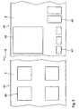
- FIGS. 1 to 6 a first embodiment of the invention described.
- a corrugated plant as in the FIGS. 1 and 6 is shown schematically, has a machine 1 for producing one-sided laminated corrugated cardboard.
- a first material web 3 of the machine 1 is supplied from a first unwinding device 2, a first material web 3 of the machine 1 is supplied.
- the material webs are endless paper webs.
- the material web 3 represents a basic trajectory for the corrugated cardboard produced in the machine 1.
- FIG. 2 shows an enlarged side view of the first material web 3 in detail.
- This has a material base layer 3a with a print quality enhancing coating 3b, a so-called primer.
- the thickness ratio between the base material layer 3a and the primer 3b is in FIG. 2 not reproduced to scale.
- the primer 3b is substantially thinner relative to the base material layer 3a than in FIG FIG. 2 shown.
- the primer 3b does not necessarily have to be present on the rolled-up material web 3, but can also be applied later to
- the first material web 3 passes through a first digital printing unit 4 with an inkjet printhead 5, which prints the top of the first material web 3 in accordance with a print job.
- the printing unit 4 is connected via a signal line 6 with a job control device 7 in connection.
- the printed first material web 3 is brought together in the machine 1 with a second material web 8, which is unrolled by a second unrolling device 9.
- the second material web 8 is carried out in the machine 1 to produce a corrugation between two corrugating rolls 10 arranged adjacent to one another.
- the second material web 8 is present after this implementation as a corrugated web 8.
- the tips of the corrugated web 8 are glued in a gluing device 11 and the corrugated web 8 is compressed in the machine 1 with the first material web 3 in a gap between a pressure roller 12 and one of the corrugating rollers 10 and interconnected.
- the machine 1 thus represents a first production unit of a production device 42 for merging material webs to a corrugated web.
- a one-sided laminated corrugated web 13 is discharged upward and around a guide roller 14 in a Working direction 15 deflected.
- the machine 1 for producing single-faced laminated corrugated webs is well known, for example from the EP 0 687 552 A (equivalent to U.S. Patent 5,632,850 ), of the DE 195 36 007 A (equivalent to GB 2,305,675 A ) or the DE 43 05 158 A1 to which reference is made for details.
- FIGS. 3 and 4 show sections of the first material web 3 in on view.
- FIG. 3 shows the material web 3 before it passes in the further course of the working direction 15 after the deflection roller 14, a preheating device 16.
- the first material web 3 has on the edge first marks 17, which are as equidistant, running transversely to the direction of 15 line markings are executed.
- Each two adjacent first marks 17 face in front of the preheating device 16, as in FIG. 3 shown, a distance a 1 to each other.
- the first web of material has at regular intervals along the working direction 15 strips with second marks 18, which are designed as equidistant short line markings parallel to the working direction 15.
- Each two adjacent second marks 18 have a distance b 1 from each other in front of the preheating device 16.
- FIG. 3 shows the material web 3 before it passes in the further course of the working direction 15 after the deflection roller 14, a preheating device 16.
- the first material web 3 has on the edge first marks 17, which are as equid
- each two adjacent first marks 17 is here with a 2 and the distance between each two adjacent second marks 18 is denoted by b 2 . Due to the shrinkage of the corrugated web 13 by the heating in the preheating device 16 and the resulting changes in the dimensions of the material web 3, the following distance relationships apply: a 2 ⁇ a 1 and b 2 ⁇ b 1 .
- a reading device 19 which is arranged above the corrugated web and thus above the marks 17, 18 carrying top of the first material web 3 and between the guide roller 14 and the preheating device 16, determines the distances a 1 and b 1 between adjacent markers 17, 18.
- the reading device 19 is designed for this purpose comparable to a barcode scanner. Via a signal line 20, the reading device 19 is connected to the job control device 7 in connection.
- the machine 1 is followed by a second unwinding device 21 for a third material web 22 as a further cover web for the corrugated web 13 in the working direction 15.
- the base web representing the first material web 3 and the cover sheet performing Third material web 22 are suitably selected paper webs. It is also sometimes customary to designate the third material web 22 as a laminating web, in which case the first material web 3 is referred to as a cover web.
- the material webs 3, 8 and 22 are unrolled at a speed of up to 400 m / min.
- the third material web 22 is first deflected by a deflection roller 23 after the second rolling device 21 so that it is guided in the working direction 15. Subsequently, the third material web 22 by two further deflection roller 24, 25 is deflected by 180 ° so that their between the guide rollers 23 and 24 downwardly facing side now facing up, the third material web 22 after the guide roller 25 opposite the working direction 15 is performed. After the deflection roller 25, the third material web 22 passes through a second printing unit 26, which forms a digital printing device 27 together with the first printing unit 4. The side of the third material web 22 pointing upwards after the deflection roller 25 is printed in the printing unit 26 by an inkjet print head 28 in accordance with a print job.
- the third material web 22 also has a two-layer construction with a base material layer and a primer such that the primer layer of the third material web 22 is printed by means of the inkjet print head 28 of the second printing unit 26. Also, the primer of the third material web 22 can be brought to after unwinding and before the second printing unit 26.
- the second printing unit 26 is for print job control via a signal line 29 with the job control device 7 in connection. After passing through the second printing unit 26, the third material web 22 with the aid of two further guide rollers 30, 31 again to substantially 180 ° deflected so that the third material web 22 is again conveyed after the deflection roller 31 substantially in the working direction 15.
- the third material web 22 is fed to the deflection roller 31 of the preheater 16. This has two superposed, heated heating rollers 32.
- the corrugated web 13 and the third web of material 22 overlap one another and partially wrap around the respective heating rollers 32.
- Behind the preheating device 16 there is arranged a gluing unit 33 with a gluing roller 34, which partially dips into a glueing bath 35.
- the corrugated web 8 of the corrugated cardboard web 13 is in contact with the gluing roller 34.
- a heating-pressing device 36 is arranged, which has a horizontal, extending in the working direction 15 table 37 with heating plates. Above the table 37 is a three rollers 38 deflected, driven endless pressure belt 39 is provided. Between the pressure belt 39 and the table 37 a Anpressspalt 40 is formed, through which the corrugated web 13 and the third material web 22 are guided and pressed there against each other.
- a corresponding heating device 36 is from the DE 199 54 754 A1 known.
- a three-ply corrugated web 41 is formed.
- the heating device 36 and the table 37 represent a second production unit of the production device 42 for merging material webs to the corrugated web 41.
- FIG. 5 shows two portions of the printed first material web 3 as part of the corrugated web 41 after exiting the heating device 36. Shown are various printing patterns 43, the z. B. for printing certain package or carton sizes and types are required.
- the print patterns 43 can, as in FIG. 5 is shown by way of example, along the working direction 15, but also transversely thereto, have different dimensions.
- the print patterns 43 are z. B. to advertising imprints to work instructions z. In the form of stencils for folding or cutting, for number or date imprints or also for imprints which treat a specific production group (batch) of the goods to be packed by means of the corrugated sheets 62, 67. These may be plain text readable information or barcodes. Due to the possibilities of the digital printing device 27, the possibilities of variation for the printing patterns 43 are practically unlimited. It is conceivable z. Example, to make the print pattern 43 so that they represent individual parts of an overall image, which results from juxtaposition of these individual print pattern parts having corrugated sheets 62, 67 and the packaging produced from these.
- FIG. 6 shows a second part of the corrugating machine following the exit of the corrugated web 41 from the heating device 36.
- a second reading device 44 Above the corrugated web 41 is at the upstream end of FIG. 6 initially arranged a second reading device 44.
- the reading device 44 is connected via a signal line 45 which is in FIG. 6 is shown interrupted, with the job control device 7 in connection.
- the second reading device 44 detects the upper side of the material web 3 in the section which is in FIG. 4 is shown.
- the second reading device 44 measures the distances a 2 , b 2 between adjacent first marks 17 and adjacent second marks 18.
- a longitudinal cutting / creasing device 46 is arranged, which consists of two creasing stations 47 arranged one behind the other and two longitudinal cutting stations 48 arranged one behind the other.
- the creasing stations 47 each have paired creasing tools 49, between which the corrugated board 41 is passed.
- the longitudinal cutting stations 48 each have rotary drivable knives 50 which are engageable with the corrugated web 41 for longitudinal cutting thereof.
- the more detailed structure of the slitting / scoring device 46 is from the DE 197 54 799 A (equivalent to US 6,071,222 ) as well as from the DE 101 31 833 A to which reference is hereby made for detail construction.
- a switch 51 is arranged in the longitudinally-cut web sections 52, 53 of the corrugated web 41 are separated from each other.
- the web sections 52, 53 are subsequently fed to a cross-cutting device 54.
- This has an upper transverse cutting roller pair 55 for the upper web section 52 and a lower transverse cutting roller pair 56 for the lower web section 53.
- the rollers of the pairs of rollers 55, 56 each carry a radially outwardly extending and perpendicular to the working direction 15 extending cutter bar 57.
- the cutter bar 57 of a cross-cutting roller pair 55, 56 cooperate for transverse transection of the web sections 52, 53 together.
- the upper cross-cutting roller pair 55 is followed by an upper conveyor belt 58, which is deflected about rotatably driven rollers 59.
- a tray 60 is arranged with vertically extending stop 61, on which from the web section 52 by means of the cross-cutting device 54 cut corrugated sheets 62 stacking a stack 63 are formed.
- the tray 60 is as in FIG. 6 indicated by a directional arrow 64, in the Height adjustable. In particular, the tray 60 may be lowered for further transport of the stack 63 to a machine floor 65 supporting the corrugator.
- the lower transverse cutting roller pair 56 is followed by a further, lower conveyor belt 66, the corrugated sheets 67, which were cut by means of the cross-cutting device 54 from the web section 53, stacked on another tray 68.
- the lower conveyor belt 66 can be raised, as indicated by a directional arrow 68a.
- the printing on the corrugated web 41 with printed patterns 43 takes place as follows: First, material webs are provided with primer layers and provided on the unwinding devices 2 and 21. However, the primer coating can also be dispensed with. An uncoated material web is then provided on the unwinding device 9. Alternatively, the primer coating can also be applied immediately before the printing units 4, 26 after unrolling the material webs. The marks 17, 18 are applied by the printing unit 4. Subsequently, a pre-run of the corrugated board plant, in which an unprinted corrugated web 41 is produced. This happens until the produced corrugated web has reached the detection range of the second reading device 44.
- the two reading devices 19, 44 then detect the distances a 1 , b 1 and a 2 , b 2 of the marks 17 and 18.
- the reading devices 19, 44 then pass this information on to the job control device 7.
- a control computer of the order control device 7 determines a longitudinal degree of shrinkage of the material webs 3, 8, 22 in the working direction 15, ie a change in the track specifications in the longitudinal direction between the web in the region of the first printing unit 4 of the printing device 27 on the one hand (reading device 19) and the web before cutting the corrugated cardboard sheets 62, 67 on the other hand (reading device 44).
- a transverse shrinkage of the material webs 3, 8, 22 is determined via the ratio of the distances b 1 , b 2 of adjacent marks 18 in the region of the reading device 19 on the one hand and in the region of the reading device 44 on the other hand.
- the determination of the transverse shrinkage and the associated markings can be dispensed with.
- the distance parameters a 1 , a 2 , b 1 , b 2 are transmitted from the reading devices 19, 44 to the job control device 7.
- the job control device 7 determines scaling factors for the printing pattern 43 to be applied by the printing units 4 and 26.
- the printing units 4 and 26 thus print the printing patterns 43 such a size reservation that due to the predetermined shrinkage of the web, the desired size of the print pattern 43 on the web sections 52, 53 results.
- the job control device 7 controls the longitudinal cutting stations 48 on the one hand and the cross cutting device 54 on the other hand via signal lines, not shown, according to the specifications of the output from the job control device 7 to the printing devices 27 print jobs.
- the corrugated sheets 62, 67 are thus cut so that the printing patterns 43 are located at predetermined positions of the corrugated sheets 62, 67.
- the print jobs relayed by the job controller 7 to the printer 27 may include small series for only a few corrugated sheets 62, 67.
- the longitudinal cutting station 48 is actuated by the job control device 7, so that the width of the web sections 52, 53 is cut accordingly.
- a cross-cutting device which is likewise controlled by the order control device 7, can be used, which makes it possible to cut corrugated cardboard sheets of different lengths in the working direction 15.
- the corrugated sheets 62, 67 can then be completely flexibly adapted in size to the shape and size of the print pattern 43 of the respective print jobs.
- the pages to be printed on the material webs 3, 22 before printing by a corresponding device, for. B. by a Druckmaschinebeläse be cleaned.
- a corresponding device for. B. by a Druck Kunststoffbuchbeläse
- the material webs 3, 22 are antistatic, so that it is avoided that z. B. accumulates dust on the pages to be printed.
- the printing of the material webs 3, 22 takes place in an air-conditioned environment. In this case, the temperature is maintained at a value which is less than 40 ° C.
- the printed pages can be sealed by applying a corresponding protective layer. Such a seal may be made before or after the corrugated sheets 62, 67 are cut.
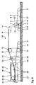
- FIG. 7 shows a second part of a corrugated board according to a second embodiment.
- the FIGS. 8 to 11 show further embodiments of corrugated board plants. Components that correspond to those already referring to the FIGS. 1 to 6 described have the same reference numerals and will not be explained again in detail.
- the heating device (not shown) is followed by a digital printing device 69. Since no relevant shrinkage of the web takes place between the printing of the corrugated web 41 and the filing of the cut corrugated sheets 62, 67, the reading devices 19, 44 of the first exemplary embodiment can be omitted here.
- the longitudinal cutting / creasing device 46 is preceded by a reading device 70, which scans the corrugated web 41 transversely and recognizes the distribution of printed patterns 43 on the corrugated web 41. Via signal lines 71, 72, the reading device 70 is in signal connection with the longitudinal cutting stations 48. Depending on the pattern recognition of the printing patterns 43 by the reading device 70, the longitudinal cutting stations 48 are controlled such that web sections 52, 53 are cut with the printing pattern distribution of corresponding width.
- a further reading device 73 is arranged, which in its detection area, the web sections 52, 53 of the corrugated web in the working direction 15, ie longitudinally, scans and thereby the distribution of Druckmustem 43 on the Corrugated web 41 along the working direction 15 detected.
- the reading device 73 is connected to the cross-cutting device 54 via a signal line 74.
- the reading device 73 controls the cross-cutting device 54 so that these corrugated sheets 62, 67 according to the print pattern distribution along the working direction 15 intersects. With the aid of the reading devices 70, 73, it is thus possible to determine a surface shape of the corrugated sheets to be set in the transverse and longitudinal dimensions and to cut these corresponding surface shapes by controlling the longitudinal cutting stations 48 or the cross-cutting device 54.
- printing units corresponding to the printing units 4 or 26 of the first exemplary embodiment may also be provided for printing individual material webs in front of the machine 1 or the heating device 36.
- the printing device 69 can be designed with two ink-jet printheads in such a way that it prints the corrugated board 41 on both sides, that is to say simultaneously, on the upper and the lower side.
- FIGS. 8 and 9 show the two parts of a corrugated board according to a third embodiment.
- the second printing unit 26 is absent.
- the deflection of the third material web which is no longer required, is eliminated by the deflecting rollers 23, 24, 25, 30, 31.
- the second embodiment is omitted first reading device 19.
- the job control device is also present in this embodiment, but not shown.
- a first material web 3 is printed, the marks 17, 18 having an initial distance, which is predetermined and before the start of production of the corrugated plant in the order controller of the third embodiment has been input. Therefore, the job control device of the third embodiment knows the distances a 1 , b 1 , although they are not measured by a reading device.
- FIG. 9 illustrated second part of the third embodiment of the corrugated board plant corresponds to the in FIG. 6 shown second part of the corrugated board plant of the first embodiment with the difference that the reading device 44 of the first embodiment, which evaluates both the marks 17 and the marks 18 with respect to their distance from each other, is functionally divided into a first reading means 75 for determining the distance marks 17 and in a second reading means 76 for determining the distance of the marks 18.
- the reading means 75, 76 are connected to the job control device of the corrugated board system of the third embodiment.
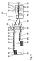
- Figures 10 and 11 show the two parts of a corrugated board plant of a fourth embodiment. These parts correspond to those of the third embodiment with the difference that in the fourth embodiment, the corrugated web is not printed from above, but from below. Therefore, in the first part of the corrugated board plant of the fourth embodiment, the printing unit 4. However, there is the first embodiment corresponding printing unit 26 for printing the underside of the third material web 22. Accordingly, in the second part of the corrugated board system of the fourth embodiment the reading devices 75, 76 are arranged underneath the corrugated web 41 in order to detect there the printing patterns printed by the printing unit 26.
- the fourth embodiment corresponds to the third embodiment.
- the reading devices 19, 44, 70, 73, 75, 76 can also be designed as a camera, in particular as a CCD camera.
- the reading device 19 has in addition to the function described above, the function of synchronizing the two printing units 4, 26 when the corrugated web 41 is to be on both sides exactly aligned pressure. For this purpose, the reading device 19 detects the time at which a particular printing pattern 43 is present in the detection area of the reading device 19.
- the job controller 7 calculates the time at which the Printing unit 26, the third material web 22 has to print in order to print this exact position for printing the opposite side of the corrugated web, so printed by the printing unit 4 top of the corrugated web 13.
Landscapes
- Engineering & Computer Science (AREA)
- Mechanical Engineering (AREA)
- Machines For Manufacturing Corrugated Board In Mechanical Paper-Making Processes (AREA)
- Making Paper Articles (AREA)
- Laminated Bodies (AREA)
Claims (10)
- Machine de fabrication de carton ondulé pour la fabrication de feuilles de carton ondulé (62, 67), comprenanta) au moins deux dispositifs de déroulement (2, 9, 21) pour dérouler des bandes de matériau (3, 8, 22) à partir de rouleaux de matériau,b) au moins un dispositif de cannelage (10) pour la fabrication d'au moins une bande ondulée (8) à partir de l'une des bandes de matériau,c) au moins un dispositif de production (1, 36, 37) pour assembler la bande ondulée (8) à la au moins une autre bande de matériau (3, 22) pour former une bande de carton ondulé (41),d) un dispositif de coupe (48, 54) pour couper à dimension des feuilles de carton ondulé (62, 67) à partir de la bande de carton ondulé (41),
caractériséee) en ce qu'est disposé, entre les dispositifs de déroulement (2, 9, 21) et le dispositif de coupe (48, 54), au moins un dispositif d'impression numérique (27; 69) pour imprimer au moins l'une des bandes (3, 22; 41; 3; 22),f) en ce qu'est prévu au moins un dispositif de mesure (19, 44; 19, 75, 76; 44; 75, 76) en liaison de signalisation avec le dispositif d'impression (27), qui est réalisé de façon à détecter des marques (17, 18) sur au moins l'une des bandes de matériau (3) et à déterminer, à partir du signal détecté, une modification des dimensions de bande entre la bande (3) au niveau du dispositif d'impression (27) et la bande (3) en amont du dispositif de coupe transversale (48, 54) destiné à couper les feuilles de carton ondulé (62, 67) au moins dans la dimension des bandes le long de la bande (3), etg) en ce qu'est prévu un dispositif de commande (7) qui détermine des facteurs de mise à l'échelle pour un motif d'impression (43) de façon à obtenir la dimension souhaitée des motifs d'impression (43). - Machine de fabrication de carton ondulé selon la revendication 1, caractérisée en ce que le dispositif d'impression (27) est disposé dans la direction de production en amont du dispositif de production (1, 36, 37).
- Machine de fabrication de carton ondulé selon la revendication 1 ou 2, caractérisée en ce qu'est prévu au moins un dispositif de chauffage (16, 36) pour le chauffage de la bande ondulée (8) et de la au moins une autre bande de matériau (3, 22) en amont du au moins un dispositif de production (1, 36, 37), le dispositif d'impression (4, 26) étant disposé en amont du dispositif de chauffage (16, 36).
- Machine de fabrication de carton ondulé selon l'une des revendications 1 à 3, caractérisée en ce qu'au moins un dispositif d'impression (69) est disposé en aval du dispositif de production (1, 36, 37).
- Machine de fabrication de carton ondulé selon l'une des revendications 1 à 4, caractérisée en ce que le dispositif d'impression (27; 69) est réalisé de telle façon que s'opère une impression unilatérale d'au moins l'une des bandes (3, 22, 41).
- Machine de fabrication de carton ondulé selon l'une des revendications 1 à 4, caractérisée en ce que le dispositif d'impression (27; 69) est réalisé de telle façon que s'opère une impression bilatérale d'au moins l'une des bandes (41).
- Machine de fabrication de carton ondulé selon la revendication 6, caractérisée en ce que sont prévus deux dispositifs de mesure (19, 44) pour détecter la modification des dimensions des bandes, l'un des dispositifs de mesure (19) étant disposé au niveau du dispositif d'impression (27) et l'autre dispositif de mesure (44) étant disposé dans la région située en amont du dispositif de coupe (48, 54).
- Procédé de fabrication de feuilles en carton ondulé au moyen d'une machine de fabrication de carton ondulé selon l'une des revendications 1 à 7, comprenant les étapes suivantes .a) mise à disposition d'une machine de fabrication de carton ondulé qui présenté :i. au moins deux dispositifs de déroulement pour dérouler des bandes de matériau sans fin, ainsi queii. au moins un dispositif de production pour produire au moins une bande de carton ondulé à partir des bandes de matériau,b) impression numérique d'au moins une bande de matériau dans la machine de fabrication de carton ondulé, etc) coupe à dimension de feuilles de carton ondulé dans la bande de carton ondulé imprimée de façon numérique en fonction de la forme et de la dimension des motifs d'impression numériques imprimés,d) les motifs d'impression étant imprimés avec une réserve dimensionnelle telle que celle-ci permet, compte tenu d'un rétrécissement prédéterminé de la bande, d'obtenir la dimension souhaitée des motifs d'impression (43) sur celle-ci.
- Procédé selon la revendication 8, caractérisé en ce que deux bandes de matériau sont imprimées de façon numérique avant d'être assemblées entre elles pour former une bande de carton ondulé.
- Procédé selon la revendication 8, caractérisé en ce qu'au moins une bande de matériau est imprimée numériquement après que celle-ci ait été assemblée à au moins une deuxième bande de matériau en formant une bande de carton ondulé.
Applications Claiming Priority (2)
| Application Number | Priority Date | Filing Date | Title |
|---|---|---|---|
| DE10312600A DE10312600A1 (de) | 2003-03-21 | 2003-03-21 | Wellpappe-Anlage sowie Verfahren zur Herstellung von Wellpappe-Bögen |
| DE10312600 | 2003-03-21 |
Publications (3)
| Publication Number | Publication Date |
|---|---|
| EP1459878A2 EP1459878A2 (fr) | 2004-09-22 |
| EP1459878A3 EP1459878A3 (fr) | 2005-10-12 |
| EP1459878B1 true EP1459878B1 (fr) | 2010-07-07 |
Family
ID=32798013
Family Applications (1)
| Application Number | Title | Priority Date | Filing Date |
|---|---|---|---|
| EP04005757A Expired - Lifetime EP1459878B1 (fr) | 2003-03-21 | 2004-03-11 | Machine de fabrication de carton ondulé et fabrication des feuilles en carton ondulé |
Country Status (6)
| Country | Link |
|---|---|
| US (1) | US20040182503A1 (fr) |
| EP (1) | EP1459878B1 (fr) |
| CN (1) | CN1532047B (fr) |
| AT (1) | ATE473096T1 (fr) |
| DE (2) | DE10312600A1 (fr) |
| ES (1) | ES2346872T3 (fr) |
Cited By (5)
| Publication number | Priority date | Publication date | Assignee | Title |
|---|---|---|---|---|
| US10642551B2 (en) | 2017-07-14 | 2020-05-05 | Georgia-Pacific Corrugated Llc | Engine for generating control plans for digital pre-print paper, sheet, and box manufacturing systems |
| US11449290B2 (en) | 2017-07-14 | 2022-09-20 | Georgia-Pacific Corrugated Llc | Control plan for paper, sheet, and box manufacturing systems |
| US11485101B2 (en) | 2017-07-14 | 2022-11-01 | Georgia-Pacific Corrugated Llc | Controls for paper, sheet, and box manufacturing systems |
| US11520544B2 (en) | 2017-07-14 | 2022-12-06 | Georgia-Pacific Corrugated Llc | Waste determination for generating control plans for digital pre-print paper, sheet, and box manufacturing systems |
| US11807480B2 (en) | 2017-07-14 | 2023-11-07 | Georgia-Pacific Corrugated Llc | Reel editor for pre-print paper, sheet, and box manufacturing systems |
Families Citing this family (42)
| Publication number | Priority date | Publication date | Assignee | Title |
|---|---|---|---|---|
| JP2003216088A (ja) * | 2002-01-28 | 2003-07-30 | Master Mind Co Ltd | 配送用トラック等を利用した広告宣伝方法 |
| US20060148631A1 (en) * | 2004-12-30 | 2006-07-06 | Corrugated Supplies Corporation | Manufacturing line for making corrugated cardboard |
| JP4671773B2 (ja) | 2005-06-10 | 2011-04-20 | 株式会社Isowa | 印刷装置 |
| US8353591B2 (en) | 2006-04-20 | 2013-01-15 | Kabushiki Kaisha Isowa | Apparatus and method for printing corrugated cardboard sheets |
| AU2007201683A1 (en) * | 2006-04-20 | 2007-11-08 | Kabushiki Kaisha Isowa | Method for manufacturing corrugated cardbaord product |
| DE102007049424A1 (de) | 2007-10-12 | 2009-04-23 | Bhs Corrugated Maschinen- Und Anlagenbau Gmbh | Wellpappe-Streifen-Transport-Einrichtung |
| DE102007049426B4 (de) | 2007-10-12 | 2009-07-16 | Bhs Corrugated Maschinen- Und Anlagenbau Gmbh | Wellpappe-Streifen-Wende-Vorrichtung |
| DE102007049422A1 (de) | 2007-10-12 | 2009-04-16 | Bhs Corrugated Maschinen- Und Anlagenbau Gmbh | Waben-Wellpappen-Anlage |
| DE102008025888A1 (de) | 2008-05-29 | 2009-12-24 | Bhs Corrugated Maschinen- Und Anlagenbau Gmbh | Falteinrichtung |
| DE102008025849A1 (de) | 2008-05-29 | 2009-12-24 | Bhs Corrugated Maschinen- Und Anlagenbau Gmbh | Stapeleinrichtung |
| DE102008025890A1 (de) | 2008-05-29 | 2009-12-24 | Bhs Corrugated Maschinen- Und Anlagenbau Gmbh | Kontinuierlicher Faltprozess |
| GB2477772A (en) * | 2010-02-12 | 2011-08-17 | Smurfit Kappa Uk Ltd | Corrugated board construction |
| DE102010031668B4 (de) | 2010-07-22 | 2012-08-02 | Bhs Corrugated Maschinen- Und Anlagenbau Gmbh | Falt - Anlage für Wellpappebahnen |
| GB2493208A (en) * | 2011-07-28 | 2013-01-30 | Ds Smith Packaging Ltd | Apparatus and method for producing printed articles |
| CN103302904A (zh) * | 2013-06-09 | 2013-09-18 | 宁夏润昌实业有限公司 | 包装纸箱用瓦楞板加工工艺及加工瓦楞板用瓦楞机 |
| CN103862725A (zh) * | 2014-03-31 | 2014-06-18 | 鼎爱环境科技(北京)有限公司 | 一种波纹纸的压辊成型设备 |
| CN103862724A (zh) * | 2014-03-31 | 2014-06-18 | 鼎爱环境科技(北京)有限公司 | 一种玻璃纤维纸的压辊成型设备 |
| WO2016165837A1 (fr) * | 2015-04-13 | 2016-10-20 | Bobst Grenchen Ag | Dispositif de stratification alimenté en bande et son procédé d'assemblage |
| CN204586068U (zh) | 2015-04-20 | 2015-08-26 | 博凯机械(上海)有限公司 | 双面机前置双重圆弧热板加热装置 |
| JP6578576B2 (ja) * | 2015-06-09 | 2019-09-25 | 株式会社Isowa | 段ボールシート製造装置 |
| JP6688575B2 (ja) * | 2015-08-10 | 2020-04-28 | 三菱重工機械システム株式会社 | 段ボールシートの切断装置及びその切断制御装置並びに段ボールシートの製造装置 |
| GB2542569B (en) * | 2015-09-22 | 2021-04-28 | Ds Smith Packaging Ltd | A combination of a printed roll and a print roll inventory map |
| DE102015218338A1 (de) | 2015-09-24 | 2017-03-30 | Bhs Corrugated Maschinen- Und Anlagenbau Gmbh | Wellpappeanlage |
| DE102015218325A1 (de) * | 2015-09-24 | 2017-03-30 | Bhs Corrugated Maschinen- Und Anlagenbau Gmbh | Wellpappe-Anlage |
| DE102015219630A1 (de) | 2015-09-24 | 2017-03-30 | Bhs Corrugated Maschinen- Und Anlagenbau Gmbh | Wellpappe-Anlage |
| CN105269874A (zh) * | 2015-11-02 | 2016-01-27 | 广东万联包装机械有限公司 | 一种与高速喷墨印刷高效融合的瓦楞纸板生产线及带图案的瓦楞纸板高速生产工艺 |
| CN108349266A (zh) | 2016-01-28 | 2018-07-31 | 惠普发展公司有限责任合伙企业 | 关于纸箱衬里的瓦楞板轧制机控制信息 |
| DE102016206016A1 (de) * | 2016-04-12 | 2017-10-12 | Bhs Corrugated Maschinen- Und Anlagenbau Gmbh | Wellpappeanlage |
| CN108260852B (zh) * | 2016-12-30 | 2020-12-11 | 中烟机械技术中心有限责任公司 | 皱纹纸预折叠装置 |
| DE102017201371A1 (de) * | 2017-01-27 | 2018-08-02 | Bhs Corrugated Maschinen- Und Anlagenbau Gmbh | Wellpappe-Anlage |
| DE102017216718A1 (de) * | 2017-09-21 | 2019-03-21 | Bhs Corrugated Maschinen- Und Anlagenbau Gmbh | Wellpappeanlage |
| DE102017216720A1 (de) * | 2017-09-21 | 2019-03-21 | Bhs Corrugated Maschinen- Und Anlagenbau Gmbh | Wellpappeanlage |
| US11472579B2 (en) | 2018-12-04 | 2022-10-18 | Gpcp Ip Holdings Llc | Film securing apparatus and method |
| DE102018211141A1 (de) * | 2018-07-05 | 2020-01-09 | Bhs Corrugated Maschinen- Und Anlagenbau Gmbh | Wellpappeanlage |
| US12077337B2 (en) | 2018-12-04 | 2024-09-03 | Yum Connect, LLC | Systems and methods for sealing a container |
| DE102019219465A1 (de) * | 2019-12-12 | 2021-06-17 | Bhs Corrugated Maschinen- Und Anlagenbau Gmbh | Anlage für eine Materialbahn |
| CN111361221A (zh) * | 2020-04-21 | 2020-07-03 | 孝感市雅都纸品包装有限公司 | 一种连续式印刷瓦楞纸板的生产方法 |
| DE202021106294U1 (de) | 2020-12-22 | 2021-11-29 | Quantumcorrugated S.R.L. | Produktionsanlage für Wellpappe |
| IT202100030563A1 (it) * | 2021-12-02 | 2023-06-02 | Quantumcorrugated S R L | Impianto di produzione di cartone ondulato con doppio lato di uscita |
| IT202200000215A1 (it) * | 2022-01-10 | 2023-07-10 | Fosber Spa | Impianto e metodo per la produzione di cartone ondulato con rilevatore di cambio d’ordine |
| DE102022205920A1 (de) * | 2022-06-10 | 2023-12-21 | Bhs Corrugated Maschinen- Und Anlagenbau Gmbh | Verfahren zum Betrieb einer Anlage, welche eine Wellpappenanlage und eine Druckmaschine aufweist, und Anlage |
| WO2025098614A1 (fr) * | 2023-11-09 | 2025-05-15 | Bhs Corrugated Maschinen- Und Anlagenbau Gmbh | Onduleuse et procédé respectif de production ou de modernisation d'une telle onduleuse |
Family Cites Families (23)
| Publication number | Priority date | Publication date | Assignee | Title |
|---|---|---|---|---|
| US3058869A (en) * | 1956-12-20 | 1962-10-16 | Rockline Realty Corp | Pre-printed corrugated board fabrication and cut-off control method and apparatus |
| US3189502A (en) * | 1961-03-03 | 1965-06-15 | West Virginia Pulp & Paper Com | Method of making impregnated corrugated paperboard sheets on a corrugator machine |
| US3335928A (en) * | 1965-06-09 | 1967-08-15 | Hurletron Inc | Control of web elongation |
| DE2745854C3 (de) * | 1977-10-12 | 1980-07-24 | Vepa Zellstoff- Und Papier-Holding Ag, Glarus (Schweiz) | Wellpappenanlage zum Herstellen bedruckter Wellpappenzuschnitte |
| DE3432587A1 (de) * | 1984-09-05 | 1986-03-13 | Werner H.K. Peters Maschinenfabrik Gmbh, 2000 Hamburg | Vorrichtung zum aufbringen von in der laenge begrenzten druckbildern auf eine wellpappenbahn |
| CH665999A5 (fr) * | 1986-03-17 | 1988-06-30 | Bobst Sa | Procede et dispositif pour commander le reglage des organes d'une machine pour les arts graphiques et le cartonnage. |
| US5147480A (en) * | 1990-05-16 | 1992-09-15 | Lin Pac, Inc. | Method of applying a finishing layer in a corrugator line |
| DE4118969C1 (fr) * | 1991-06-08 | 1992-07-30 | Thimm Kg, 3410 Northeim, De | |
| FR2708011B1 (fr) * | 1993-07-20 | 1995-10-13 | Otor Sa | Machine et procédé de fabrication d'une feuille de carton ondulé simple face. |
| US5365847A (en) * | 1993-09-22 | 1994-11-22 | Rockwell International Corporation | Control system for a printing press |
| DE4402338B4 (de) * | 1994-01-27 | 2004-04-08 | Heidelberger Druckmaschinen Ag | Verfahren zum Steuern von geometrischen Veränderungen eines Bedruckstoffes bei einem Betriebsvorgang des Druckens und Trocknens eines Druckbilds |
| DE4420726A1 (de) * | 1994-06-16 | 1995-12-21 | Bhs Corr Masch & Anlagenbau | Maschine zur Herstellung einer mindestens einseitig kaschierten Wellpappebahn |
| DE4425199A1 (de) * | 1994-07-16 | 1996-01-18 | Heinr Aug Schoeller Soehne Gmb | Verfahren zum Bedrucken von Wellpappe sowie Einrichtung zur Durchführung des Verfahrens |
| KR0181565B1 (ko) * | 1995-04-11 | 1999-04-15 | 김승무 | 다중 골심판지 성형방법 및 그 장치 |
| US5658432A (en) * | 1995-08-24 | 1997-08-19 | Measurex Devron Inc. | Apparatus and method of determining sheet shrinkage or expansion characteristics |
| US5882746A (en) * | 1995-12-28 | 1999-03-16 | Hoffman Environmental Systems, Inc. | Laminated package and method of producing the same |
| DE19754799A1 (de) * | 1997-12-10 | 1999-06-17 | Bhs Corr Masch & Anlagenbau | Längsschneide- und Rill-Maschine für Wellpappebahnen |
| IT243960Y1 (it) * | 1998-04-23 | 2002-03-06 | Fotoba Internat S A S Di Pietr | Dispositivo automatico di taglio in squadra di carta ed altrisupporti grafici e fotografici |
| GB2343415C (en) * | 1999-03-09 | 2014-10-22 | Richard Gardiner | An ink jet printer |
| US6874420B2 (en) * | 1999-10-22 | 2005-04-05 | Cc1, Inc. | System and method for register mark recognition |
| FI116687B (fi) * | 2000-08-15 | 2006-01-31 | Avenira Oy | Menetelmä ja sovitelma kartongin valmistamiseksi ja kartonkituote |
| US6491361B1 (en) * | 2000-11-09 | 2002-12-10 | Encad, Inc. | Digital media cutter |
| JP2002337253A (ja) * | 2001-05-15 | 2002-11-27 | Hiroshi Yanagisawa | 段ボール印刷システム |
-
2003
- 2003-03-21 DE DE10312600A patent/DE10312600A1/de not_active Withdrawn
-
2004
- 2004-03-11 ES ES04005757T patent/ES2346872T3/es not_active Expired - Lifetime
- 2004-03-11 DE DE502004011351T patent/DE502004011351D1/de not_active Expired - Lifetime
- 2004-03-11 AT AT04005757T patent/ATE473096T1/de active
- 2004-03-11 EP EP04005757A patent/EP1459878B1/fr not_active Expired - Lifetime
- 2004-03-19 CN CN2004100294995A patent/CN1532047B/zh not_active Expired - Fee Related
- 2004-03-22 US US10/805,337 patent/US20040182503A1/en not_active Abandoned
Cited By (8)
| Publication number | Priority date | Publication date | Assignee | Title |
|---|---|---|---|---|
| US10642551B2 (en) | 2017-07-14 | 2020-05-05 | Georgia-Pacific Corrugated Llc | Engine for generating control plans for digital pre-print paper, sheet, and box manufacturing systems |
| US11093186B2 (en) | 2017-07-14 | 2021-08-17 | Georgia-Pacific Corrugated Llc | Engine for generating control plans for digital pre-print paper, sheet, and box manufacturing systems |
| US11449290B2 (en) | 2017-07-14 | 2022-09-20 | Georgia-Pacific Corrugated Llc | Control plan for paper, sheet, and box manufacturing systems |
| US11485101B2 (en) | 2017-07-14 | 2022-11-01 | Georgia-Pacific Corrugated Llc | Controls for paper, sheet, and box manufacturing systems |
| US11520544B2 (en) | 2017-07-14 | 2022-12-06 | Georgia-Pacific Corrugated Llc | Waste determination for generating control plans for digital pre-print paper, sheet, and box manufacturing systems |
| US11807480B2 (en) | 2017-07-14 | 2023-11-07 | Georgia-Pacific Corrugated Llc | Reel editor for pre-print paper, sheet, and box manufacturing systems |
| US11907595B2 (en) | 2017-07-14 | 2024-02-20 | Georgia-Pacific Corrugated Llc | Control plan for paper, sheet, and box manufacturing systems |
| US11911992B2 (en) | 2017-07-14 | 2024-02-27 | Georgia-Pacific Corrugated Llc | Controls for paper, sheet, and box manufacturing systems |
Also Published As
| Publication number | Publication date |
|---|---|
| ATE473096T1 (de) | 2010-07-15 |
| CN1532047A (zh) | 2004-09-29 |
| US20040182503A1 (en) | 2004-09-23 |
| CN1532047B (zh) | 2010-12-01 |
| EP1459878A3 (fr) | 2005-10-12 |
| DE502004011351D1 (de) | 2010-08-19 |
| DE10312600A1 (de) | 2004-10-07 |
| ES2346872T3 (es) | 2010-10-21 |
| EP1459878A2 (fr) | 2004-09-22 |
Similar Documents
| Publication | Publication Date | Title |
|---|---|---|
| EP1459878B1 (fr) | Machine de fabrication de carton ondulé et fabrication des feuilles en carton ondulé | |
| DE10312601A1 (de) | Material-Bahn sowie Verfahren zur Herstellung von Wellpappe | |
| EP3442785B1 (fr) | Installation de carton ondulé | |
| EP3156199B1 (fr) | Installation de carton ondulé | |
| EP1820899A1 (fr) | Procédé destiné à la pose d'étiquettes RFID dans du carton ondulé | |
| EP2060388A2 (fr) | Installation de carton ondulé et procédé de fabrication d'une bande de carton ondulé sans fin | |
| EP3459725B1 (fr) | Installation à cartons ondulés | |
| EP3150378A2 (fr) | Installation et procédé pour la production de carton ondulé | |
| DE69905123T2 (de) | Verfahren zum Wechseln zwischen Bestellungen für eine Wellpappenmaschine | |
| EP3459724A2 (fr) | Installation de carton ondulé | |
| EP3354426A1 (fr) | Correction de position pour les marques de repérage en coupant carton ondulé | |
| EP3793818B1 (fr) | Onduleuse | |
| DE2748675C2 (de) | Verfahren und Vorrichtung zur Herstellung von kaschierten Bögen | |
| DE3602210C2 (fr) | ||
| DE102021212245B4 (de) | Anordnung für eine Wellpappeanlage | |
| EP0234349B1 (fr) | Dispositif pour empiler des coupons de carton ondulé double face | |
| DE10331357A1 (de) | Wellpappe-Anlage | |
| DE102021006685A1 (de) | Druckanordnung | |
| EP1291163A1 (fr) | Système pour la fabrication de carton ondulé | |
| DE102016200481B4 (de) | Vorrichtung und Verfahren zur Be- und/oder Verarbeitung bahnförmigen Bedruckstoffs | |
| WO2022229022A2 (fr) | Dispositif de fabrication d'une feuille de carton ondulé contrecollée sur les deux faces | |
| EP4605233A1 (fr) | Ensemble d'impression, procédé d'impression et bande de matériau | |
| DE102021213360A1 (de) | Druckanordnung | |
| DE2748675B2 (fr) | ||
| DE8116439U1 (de) | Vorrichtung zur Herstellung eines gdruckten, personalisierten Werbemittels |
Legal Events
| Date | Code | Title | Description |
|---|---|---|---|
| PUAI | Public reference made under article 153(3) epc to a published international application that has entered the european phase |
Free format text: ORIGINAL CODE: 0009012 |
|
| AK | Designated contracting states |
Kind code of ref document: A2 Designated state(s): AT BE BG CH CY CZ DE DK EE ES FI FR GB GR HU IE IT LI LU MC NL PL PT RO SE SI SK TR |
|
| AX | Request for extension of the european patent |
Extension state: AL LT LV MK |
|
| PUAL | Search report despatched |
Free format text: ORIGINAL CODE: 0009013 |
|
| AK | Designated contracting states |
Kind code of ref document: A3 Designated state(s): AT BE BG CH CY CZ DE DK EE ES FI FR GB GR HU IE IT LI LU MC NL PL PT RO SE SI SK TR |
|
| AX | Request for extension of the european patent |
Extension state: AL LT LV MK |
|
| 17P | Request for examination filed |
Effective date: 20060210 |
|
| AKX | Designation fees paid |
Designated state(s): AT BE BG CH CY CZ DE DK EE ES FI FR GB GR HU IE IT LI LU MC NL PL PT RO SE SI SK TR |
|
| 17Q | First examination report despatched |
Effective date: 20080429 |
|
| GRAP | Despatch of communication of intention to grant a patent |
Free format text: ORIGINAL CODE: EPIDOSNIGR1 |
|
| RTI1 | Title (correction) |
Free format text: CORRUGATED BOARD MACHINE AND MANUFACTURING OF CORRUGATED BOARD SHEETS |
|
| GRAS | Grant fee paid |
Free format text: ORIGINAL CODE: EPIDOSNIGR3 |
|
| GRAA | (expected) grant |
Free format text: ORIGINAL CODE: 0009210 |
|
| AK | Designated contracting states |
Kind code of ref document: B1 Designated state(s): AT BE BG CH CY CZ DE DK EE ES FI FR GB GR HU IE IT LI LU MC NL PL PT RO SE SI SK TR |
|
| REG | Reference to a national code |
Ref country code: GB Ref legal event code: FG4D Free format text: NOT ENGLISH |
|
| REG | Reference to a national code |
Ref country code: CH Ref legal event code: EP |
|
| REG | Reference to a national code |
Ref country code: IE Ref legal event code: FG4D |
|
| REF | Corresponds to: |
Ref document number: 502004011351 Country of ref document: DE Date of ref document: 20100819 Kind code of ref document: P |
|
| REG | Reference to a national code |
Ref country code: ES Ref legal event code: FG2A Ref document number: 2346872 Country of ref document: ES Kind code of ref document: T3 |
|
| REG | Reference to a national code |
Ref country code: NL Ref legal event code: VDEP Effective date: 20100707 |
|
| PG25 | Lapsed in a contracting state [announced via postgrant information from national office to epo] |
Ref country code: SI Free format text: LAPSE BECAUSE OF FAILURE TO SUBMIT A TRANSLATION OF THE DESCRIPTION OR TO PAY THE FEE WITHIN THE PRESCRIBED TIME-LIMIT Effective date: 20100707 |
|
| PG25 | Lapsed in a contracting state [announced via postgrant information from national office to epo] |
Ref country code: FI Free format text: LAPSE BECAUSE OF FAILURE TO SUBMIT A TRANSLATION OF THE DESCRIPTION OR TO PAY THE FEE WITHIN THE PRESCRIBED TIME-LIMIT Effective date: 20100707 Ref country code: NL Free format text: LAPSE BECAUSE OF FAILURE TO SUBMIT A TRANSLATION OF THE DESCRIPTION OR TO PAY THE FEE WITHIN THE PRESCRIBED TIME-LIMIT Effective date: 20100707 |
|
| REG | Reference to a national code |
Ref country code: IE Ref legal event code: FD4D |
|
| PG25 | Lapsed in a contracting state [announced via postgrant information from national office to epo] |
Ref country code: PT Free format text: LAPSE BECAUSE OF FAILURE TO SUBMIT A TRANSLATION OF THE DESCRIPTION OR TO PAY THE FEE WITHIN THE PRESCRIBED TIME-LIMIT Effective date: 20101108 Ref country code: PL Free format text: LAPSE BECAUSE OF FAILURE TO SUBMIT A TRANSLATION OF THE DESCRIPTION OR TO PAY THE FEE WITHIN THE PRESCRIBED TIME-LIMIT Effective date: 20100707 Ref country code: BG Free format text: LAPSE BECAUSE OF FAILURE TO SUBMIT A TRANSLATION OF THE DESCRIPTION OR TO PAY THE FEE WITHIN THE PRESCRIBED TIME-LIMIT Effective date: 20101007 Ref country code: CY Free format text: LAPSE BECAUSE OF FAILURE TO SUBMIT A TRANSLATION OF THE DESCRIPTION OR TO PAY THE FEE WITHIN THE PRESCRIBED TIME-LIMIT Effective date: 20100707 |
|
| PG25 | Lapsed in a contracting state [announced via postgrant information from national office to epo] |
Ref country code: GR Free format text: LAPSE BECAUSE OF FAILURE TO SUBMIT A TRANSLATION OF THE DESCRIPTION OR TO PAY THE FEE WITHIN THE PRESCRIBED TIME-LIMIT Effective date: 20101008 Ref country code: SE Free format text: LAPSE BECAUSE OF FAILURE TO SUBMIT A TRANSLATION OF THE DESCRIPTION OR TO PAY THE FEE WITHIN THE PRESCRIBED TIME-LIMIT Effective date: 20100707 |
|
| PG25 | Lapsed in a contracting state [announced via postgrant information from national office to epo] |
Ref country code: DK Free format text: LAPSE BECAUSE OF FAILURE TO SUBMIT A TRANSLATION OF THE DESCRIPTION OR TO PAY THE FEE WITHIN THE PRESCRIBED TIME-LIMIT Effective date: 20100707 Ref country code: IE Free format text: LAPSE BECAUSE OF FAILURE TO SUBMIT A TRANSLATION OF THE DESCRIPTION OR TO PAY THE FEE WITHIN THE PRESCRIBED TIME-LIMIT Effective date: 20100707 |
|
| PLBE | No opposition filed within time limit |
Free format text: ORIGINAL CODE: 0009261 |
|
| STAA | Information on the status of an ep patent application or granted ep patent |
Free format text: STATUS: NO OPPOSITION FILED WITHIN TIME LIMIT |
|
| PG25 | Lapsed in a contracting state [announced via postgrant information from national office to epo] |
Ref country code: SK Free format text: LAPSE BECAUSE OF FAILURE TO SUBMIT A TRANSLATION OF THE DESCRIPTION OR TO PAY THE FEE WITHIN THE PRESCRIBED TIME-LIMIT Effective date: 20100707 Ref country code: RO Free format text: LAPSE BECAUSE OF FAILURE TO SUBMIT A TRANSLATION OF THE DESCRIPTION OR TO PAY THE FEE WITHIN THE PRESCRIBED TIME-LIMIT Effective date: 20100707 Ref country code: CZ Free format text: LAPSE BECAUSE OF FAILURE TO SUBMIT A TRANSLATION OF THE DESCRIPTION OR TO PAY THE FEE WITHIN THE PRESCRIBED TIME-LIMIT Effective date: 20100707 Ref country code: EE Free format text: LAPSE BECAUSE OF FAILURE TO SUBMIT A TRANSLATION OF THE DESCRIPTION OR TO PAY THE FEE WITHIN THE PRESCRIBED TIME-LIMIT Effective date: 20100707 |
|
| 26N | No opposition filed |
Effective date: 20110408 |
|
| REG | Reference to a national code |
Ref country code: DE Ref legal event code: R097 Ref document number: 502004011351 Country of ref document: DE Effective date: 20110408 |
|
| BERE | Be: lapsed |
Owner name: BHS CORRUGATED MASCHINEN-UND ANLAGENBAU G.M.B.H. Effective date: 20110331 |
|
| PG25 | Lapsed in a contracting state [announced via postgrant information from national office to epo] |
Ref country code: MC Free format text: LAPSE BECAUSE OF NON-PAYMENT OF DUE FEES Effective date: 20110331 |
|
| REG | Reference to a national code |
Ref country code: CH Ref legal event code: PL |
|
| PG25 | Lapsed in a contracting state [announced via postgrant information from national office to epo] |
Ref country code: BE Free format text: LAPSE BECAUSE OF NON-PAYMENT OF DUE FEES Effective date: 20110331 |
|
| PG25 | Lapsed in a contracting state [announced via postgrant information from national office to epo] |
Ref country code: LI Free format text: LAPSE BECAUSE OF NON-PAYMENT OF DUE FEES Effective date: 20110331 Ref country code: CH Free format text: LAPSE BECAUSE OF NON-PAYMENT OF DUE FEES Effective date: 20110331 |
|
| REG | Reference to a national code |
Ref country code: AT Ref legal event code: MM01 Ref document number: 473096 Country of ref document: AT Kind code of ref document: T Effective date: 20110311 |
|
| PG25 | Lapsed in a contracting state [announced via postgrant information from national office to epo] |
Ref country code: AT Free format text: LAPSE BECAUSE OF NON-PAYMENT OF DUE FEES Effective date: 20110311 |
|
| PG25 | Lapsed in a contracting state [announced via postgrant information from national office to epo] |
Ref country code: LU Free format text: LAPSE BECAUSE OF NON-PAYMENT OF DUE FEES Effective date: 20110311 |
|
| PG25 | Lapsed in a contracting state [announced via postgrant information from national office to epo] |
Ref country code: TR Free format text: LAPSE BECAUSE OF FAILURE TO SUBMIT A TRANSLATION OF THE DESCRIPTION OR TO PAY THE FEE WITHIN THE PRESCRIBED TIME-LIMIT Effective date: 20100707 |
|
| PG25 | Lapsed in a contracting state [announced via postgrant information from national office to epo] |
Ref country code: HU Free format text: LAPSE BECAUSE OF FAILURE TO SUBMIT A TRANSLATION OF THE DESCRIPTION OR TO PAY THE FEE WITHIN THE PRESCRIBED TIME-LIMIT Effective date: 20100707 |
|
| REG | Reference to a national code |
Ref country code: FR Ref legal event code: PLFP Year of fee payment: 13 |
|
| REG | Reference to a national code |
Ref country code: FR Ref legal event code: PLFP Year of fee payment: 14 |
|
| REG | Reference to a national code |
Ref country code: FR Ref legal event code: PLFP Year of fee payment: 15 |
|
| PGFP | Annual fee paid to national office [announced via postgrant information from national office to epo] |
Ref country code: FR Payment date: 20210319 Year of fee payment: 18 |
|
| PGFP | Annual fee paid to national office [announced via postgrant information from national office to epo] |
Ref country code: GB Payment date: 20210324 Year of fee payment: 18 |
|
| PGFP | Annual fee paid to national office [announced via postgrant information from national office to epo] |
Ref country code: DE Payment date: 20210521 Year of fee payment: 18 Ref country code: IT Payment date: 20210331 Year of fee payment: 18 |
|
| PGFP | Annual fee paid to national office [announced via postgrant information from national office to epo] |
Ref country code: ES Payment date: 20210421 Year of fee payment: 18 |
|
| REG | Reference to a national code |
Ref country code: DE Ref legal event code: R119 Ref document number: 502004011351 Country of ref document: DE |
|
| GBPC | Gb: european patent ceased through non-payment of renewal fee |
Effective date: 20220311 |
|
| PG25 | Lapsed in a contracting state [announced via postgrant information from national office to epo] |
Ref country code: GB Free format text: LAPSE BECAUSE OF NON-PAYMENT OF DUE FEES Effective date: 20220311 Ref country code: FR Free format text: LAPSE BECAUSE OF NON-PAYMENT OF DUE FEES Effective date: 20220331 Ref country code: DE Free format text: LAPSE BECAUSE OF NON-PAYMENT OF DUE FEES Effective date: 20221001 |
|
| REG | Reference to a national code |
Ref country code: ES Ref legal event code: FD2A Effective date: 20230428 |
|
| PG25 | Lapsed in a contracting state [announced via postgrant information from national office to epo] |
Ref country code: IT Free format text: LAPSE BECAUSE OF NON-PAYMENT OF DUE FEES Effective date: 20220311 |
|
| P01 | Opt-out of the competence of the unified patent court (upc) registered |
Effective date: 20230527 |
|
| PG25 | Lapsed in a contracting state [announced via postgrant information from national office to epo] |
Ref country code: ES Free format text: LAPSE BECAUSE OF NON-PAYMENT OF DUE FEES Effective date: 20220312 |