EP1462392A2 - Antriebseinrichtung für eine Lagervorrichtung - Google Patents
Antriebseinrichtung für eine Lagervorrichtung Download PDFInfo
- Publication number
- EP1462392A2 EP1462392A2 EP04007172A EP04007172A EP1462392A2 EP 1462392 A2 EP1462392 A2 EP 1462392A2 EP 04007172 A EP04007172 A EP 04007172A EP 04007172 A EP04007172 A EP 04007172A EP 1462392 A2 EP1462392 A2 EP 1462392A2
- Authority
- EP
- European Patent Office
- Prior art keywords
- drive device
- cable
- storage
- platform
- drive
- Prior art date
- Legal status (The legal status is an assumption and is not a legal conclusion. Google has not performed a legal analysis and makes no representation as to the accuracy of the status listed.)
- Withdrawn
Links
Images

Classifications
-
- B—PERFORMING OPERATIONS; TRANSPORTING
- B65—CONVEYING; PACKING; STORING; HANDLING THIN OR FILAMENTARY MATERIAL
- B65G—TRANSPORT OR STORAGE DEVICES, e.g. CONVEYORS FOR LOADING OR TIPPING, SHOP CONVEYOR SYSTEMS OR PNEUMATIC TUBE CONVEYORS
- B65G1/00—Storing articles, individually or in orderly arrangement, in warehouses or magazines
- B65G1/02—Storage devices
- B65G1/04—Storage devices mechanical
- B65G1/0407—Storage devices mechanical using stacker cranes
- B65G1/0435—Storage devices mechanical using stacker cranes with pulling or pushing means on either stacking crane or stacking area
Definitions
- the invention relates to a drive device for a bearing device in the form of a mechanical cabinet with a variety of storage goods carriers, by the Drive device with a vertically movable platform selectively to a storage / retrieval opening are movable.
- Such a drive device is known from US-A-5,810,540.
- a mechanical cabinet described in which a variety of cassette-like Storage goods carriers can be pushed in or pushed out in two side shelf frames. Between A feeder platform is in these two right and left stacking columns Height direction can be moved, so the individual storage goods carrier from the rack frame can be removed and fed to an opening for outsourcing can.
- the drive device is on the
- the height-adjustable platform is relatively complex, particularly since there are multiple platforms Deflections of the drive rope are required. This will drive the Height positioning of the platform is relatively imprecise. It also suffers due to the multiple Deflection of the rope's life or maintenance duration.
- the invention has for its object a drive device for To create storage devices, with a simple design, a high Positioning accuracy and maintenance period is achieved.
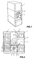
- FIG. 1 is a perspective view of a bearing device 1 in the form of a mechanical cabinet shown, which essentially consists of two in a row arranged shelf frame 2 (see also Fig. 2 and 3), in which a variety of flat storage goods carriers 3 can be stored on lateral support angles 2a.
- the Storage goods carriers 3 are in this case by a feeder platform 4 from a storage / retrieval opening 5 picked up and to the respective compartment in the shelf frame 2 transported.
- the outsourcing takes place in the reverse manner by the respective Storage goods carrier 3 of corresponding support angles 2a at a predetermined location of the rack frame 2 is then pulled from the platform 4 to the storage / retrieval level the storage / retrieval opening 5 is moved and then pushed out into it.
- the storage or retrieval is generally controlled by means of the Drive device processor-controlled, the control part, for example, behind a Control panel 12 shown schematically here is attached, with which certain Specialist locations in the shelf frame 2 can be selected.
- a height sensor can also be provided, which measures the height of the storage Storage goods carrier 3 and then a corresponding place shelf frame 2 is assigned.
- chain drives 9 are provided, with which the respective Storage goods carrier 3 can be taken from the storage opening 5 or onto this can be pushed out.
- a front or rear engagement profile 21 (only on some storage goods carriers 3 indicated by a hook) for the chain drives 9 intended.
- this engagement profile 21 at the front or rear end of the Storage goods carrier 3 can thus be the chain drive 9 with drivers (not shown, because at known) intervene.
- FIG. 2 shows a sectional illustration of the bearing device 1 according to FIG. 1, wherein in particular the arrangement of the two shelf frames 2 and the platform 4 can be seen with which, after inserting a (here loaded) storage goods carrier 3 by hand, by means of robots or other storage and retrieval machines, the storage goods carriers 3 to the allocated storage space in the rack frame 2 are movable.
- This is done by Vertical movement of the platform 4 by means of a closed rope strand, in each case consisting of a support cable 10 and a counter-pull cable 11.
- the support cable 10 is there guided over an upper deflection wheel 7 and with a pivot point 16 on the platform 4 attached.
- a second articulation point 16 is provided adjacent to this, at which the Counter rope 11 is attached, both cables 10 and 11 are taut and by a common cable drum 8 can be developed in opposite directions.
- the suspension cable 10 is on the cable drum 8 wound up, while the pulling rope 11 is unwound by the same length.
- the Platform is in the vertical direction on a guide rail 6 (see also Fig. 3) performed, for example with a linear bearing 6 'schematically indicated here. If however, more than three suspension ropes 10 are provided on the platform 4, in particular four at each corner area of the platform, as in the embodiment according to FIG. 3, a relative simple guide bearing 6 'is sufficient, as this causes tilting movements of the platform 4 the three- or four-point suspension are excluded anyway.
- each of a common cable drum 8 up or in opposite directions can be developed.
- the visible ones here two cable drums 8 are arranged along a crossbar 13, which the two modular shelf frame 2 connects. This results in a special one stable support of the cable drums 8 and optimal force transmission into the frame, see above that even with high forces, for example when braking quickly Platform 4, hardly any rope elongations occur. This will result in positioning errors or Ringing in the drive, which is dynamically very stiff in this case, in conjunction practically avoided with the respective pull rope 11.
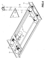
- FIG. 4 shows a modified embodiment of the mounting of the four cable drums 8 shown.
- the course of the rope of a closed rope strand is also indicated, the suspension cable 10 (after deflection on the upper deflection wheel 7) and the counter-pulling cable 11 meet at adjacent articulation points 16 on the platform 4, but also at the respective one common rope drum 8 for the opposite winding or unwinding at Height movement of the platform 4.
- the (here four) rope drums 8 are different from the Fig. 3 is not mounted parallel to the crossbar 13, but aligned at right angles to it. This results in a simplified design of the synchronous cable drum drive via shafts 14, which are driven by a common motor 15. 3 there is also the synchronous drive of the four cable drums 8 (the rear two are covered) by a drive box on the side (with chains or Belt drive to ensure the synchronization of the rope strands 10/11).
Landscapes
- Engineering & Computer Science (AREA)
- Mechanical Engineering (AREA)
- Warehouses Or Storage Devices (AREA)
Abstract
Description
Claims (9)
- Antriebseinrichtung für eine Lagervorrichtung in Form eines mechanischen Schrankes mit einer Vielzahl von Lagergutträgern, die von der Antriebseinrichtung mit einer höhenbeweglichen Plattform selektiv zu einer Ein-/Auslageröffnung bewegbar sind, dadurch gekennzeichnet, dass
die Plattform (4) an wenigstens zwei geschlossenen Seilsträngen bestehend aus Tragseil (10) und Gegenzugseil (11) befestigt ist, die jeweils von einer gemeinsamen Seiltrommel (8) abwickelbar sind. - Antriebseinrichtung nach Anspruch 1, dadurch gekennzeichnet, dass die Lagervorrichtung (1) durch zwei Regalrahmen (2) gebildet ist, zwischen denen die Tragseile (10) um oben gelagerte Umlenkräder (7) beweglich ist.
- Antriebseinrichtung nach Anspruch 1 oder 2, dadurch gekennzeichnet, dass die Seiltrommeln (8) an einer unteren Quertraverse (13) zwischen den Regalrahmen (2) angeordnet ist.
- Antriebseinrichtung nach einem der Ansprüche 1 bis 3, dadurch gekennzeichnet, dass jeweils zwei Seiltrommeln (8) einander gegenüberliegend angeordnet ist.
- Antriebseinrichtung nach Anspruch 3 oder 4, dadurch gekennzeichnet, dass die Achsen der Seiltrommeln (8) parallel zur Quertraverse (13) angeordnet sind.
- Antriebseinrichtung nach Anspruch 3 oder 4, dadurch gekennzeichnet, dass die Achsen der Seiltrommeln (8) rechtwinklig zur Quertraverse (13) ausgerichtet sind.
- Antriebseinrichtung nach Anspruch 5 oder 6, dadurch gekennzeichnet, dass je zwei Seiltrommeln (8) einen gemeinsamen Antriebsstrang (14) aufweisen.
- Antriebseinrichtung nach einem der Ansprüche 1 bis 7, dadurch gekennzeichnet, dass vier Seiltrommeln (8) vorgesehen sind, deren Seile (10, 11) jeweils im Eckbereich der Plattform (4) angelenkt sind.
- Antriebseinrichtung nach Anspruch 8, dadurch gekennzeichnet, dass die Anlenkpunkte (16) des Tragseils (10) und des Gegenzugseils (11) jeweils unmittelbar benachbart zueinander angeordnet sind.
Applications Claiming Priority (2)
| Application Number | Priority Date | Filing Date | Title |
|---|---|---|---|
| DE20304872U | 2003-03-25 | ||
| DE20304872U DE20304872U1 (de) | 2003-03-25 | 2003-03-25 | Antriebseinrichtung für eine Lagervorrichtung |
Publications (2)
| Publication Number | Publication Date |
|---|---|
| EP1462392A2 true EP1462392A2 (de) | 2004-09-29 |
| EP1462392A3 EP1462392A3 (de) | 2004-11-10 |
Family
ID=32240673
Family Applications (1)
| Application Number | Title | Priority Date | Filing Date |
|---|---|---|---|
| EP04007172A Withdrawn EP1462392A3 (de) | 2003-03-25 | 2004-03-25 | Antriebseinrichtung für eine Lagervorrichtung |
Country Status (2)
| Country | Link |
|---|---|
| EP (1) | EP1462392A3 (de) |
| DE (1) | DE20304872U1 (de) |
Cited By (5)
| Publication number | Priority date | Publication date | Assignee | Title |
|---|---|---|---|---|
| EP2881905A1 (de) | 2013-12-09 | 2015-06-10 | Cleveron Ltd. | Selbstbedienungs-Paketterminal |
| EP3142085A1 (de) * | 2015-09-12 | 2017-03-15 | Cleveron AS | Paketterminal und verfahren zur optimierung der paketkapazität im paketterminal |
| IT201700010427A1 (it) * | 2017-01-31 | 2018-07-31 | Tor Mec Ambrosi S R L | Magazzino automatico modulare per lo stoccaggio di prodotti industriali |
| US10357804B2 (en) | 2017-04-23 | 2019-07-23 | Cleveron As | Method for increasing the speed of discharge and insertion of postal objects in a parcel terminal and a parcel terminal |
| US11341346B2 (en) | 2015-09-12 | 2022-05-24 | Cleveron As | Self-service parcel terminal with optimized shelving arrangement |
Families Citing this family (2)
| Publication number | Priority date | Publication date | Assignee | Title |
|---|---|---|---|---|
| DE202008016153U1 (de) * | 2008-12-08 | 2010-04-01 | Kardex Produktion Deutschland Gmbh | Regalverkleidung, insbesondere für Umlaufregale |
| IT201900015971A1 (it) * | 2019-09-11 | 2021-03-11 | Antonio Piazza | Torre multipiano smontabile e componibile con contenitori sovrapposti in verticale e contrapposti trasversalmente e tra loro mobili per prodotti lungiformi |
Family Cites Families (4)
| Publication number | Priority date | Publication date | Assignee | Title |
|---|---|---|---|---|
| US2940068A (en) * | 1957-10-28 | 1960-06-07 | Sperry Rand Corp | Large scale memory device |
| US5810540A (en) * | 1996-04-30 | 1998-09-22 | Castaldi; John | Automated storage and retrieval system and bin insertion/extraction mechanism therefor |
| US5915909A (en) * | 1997-11-17 | 1999-06-29 | Kardex Systems, Inc. | Automatic vertical storage and retrieval system |
| DE20105582U1 (de) * | 2001-03-23 | 2002-08-01 | Bellheimer Metallwerk GmbH, 76756 Bellheim | Lagerlift |
-
2003
- 2003-03-25 DE DE20304872U patent/DE20304872U1/de not_active Expired - Lifetime
-
2004
- 2004-03-25 EP EP04007172A patent/EP1462392A3/de not_active Withdrawn
Cited By (13)
| Publication number | Priority date | Publication date | Assignee | Title |
|---|---|---|---|---|
| US9242810B2 (en) | 2013-12-09 | 2016-01-26 | Cleveron Ltd | Self-service parcel terminal |
| EP2881905A1 (de) | 2013-12-09 | 2015-06-10 | Cleveron Ltd. | Selbstbedienungs-Paketterminal |
| US11341346B2 (en) | 2015-09-12 | 2022-05-24 | Cleveron As | Self-service parcel terminal with optimized shelving arrangement |
| EP3142085A1 (de) * | 2015-09-12 | 2017-03-15 | Cleveron AS | Paketterminal und verfahren zur optimierung der paketkapazität im paketterminal |
| US11829835B2 (en) | 2015-09-12 | 2023-11-28 | Cleveron As | Self-service parcel terminal with optimized shelving arrangement |
| EP4009294A1 (de) * | 2015-09-12 | 2022-06-08 | Cleveron AS | Paketterminal und verfahren zur optimierung der paketkapazität im paketterminal |
| IT201700010427A1 (it) * | 2017-01-31 | 2018-07-31 | Tor Mec Ambrosi S R L | Magazzino automatico modulare per lo stoccaggio di prodotti industriali |
| CN110520370B (zh) * | 2017-01-31 | 2021-12-10 | 汤米克安布罗西公司 | 用于储存工业产品的模块化自动仓库 |
| CN110520370A (zh) * | 2017-01-31 | 2019-11-29 | 汤米克安布罗西公司 | 用于储存工业产品的模块化自动仓库 |
| US11760568B2 (en) | 2017-01-31 | 2023-09-19 | Ambrosi S.R.L. | Modular automatic warehouse for storing industrial products |
| WO2018142241A1 (en) * | 2017-01-31 | 2018-08-09 | Tor.Mec Ambrosi S.R.L. | Modular automatic warehouse for storing industrial products |
| EP3577040B1 (de) | 2017-01-31 | 2024-03-06 | Ambrosi S.r.l. | Modulares automatisches lager zur lagerung von industrieprodukten |
| US10357804B2 (en) | 2017-04-23 | 2019-07-23 | Cleveron As | Method for increasing the speed of discharge and insertion of postal objects in a parcel terminal and a parcel terminal |
Also Published As
| Publication number | Publication date |
|---|---|
| DE20304872U1 (de) | 2004-04-29 |
| EP1462392A3 (de) | 2004-11-10 |
Similar Documents
| Publication | Publication Date | Title |
|---|---|---|
| EP1449795B1 (de) | Regalbediengerät | |
| DE2313429A1 (de) | Speicher- und wiedergewinnungsvorrichtung fuer aktenpapiere | |
| DE202004004620U1 (de) | Lagersystem | |
| EP2530042B1 (de) | Aufzug | |
| DE69324124T2 (de) | Regalbedienungsgerät | |
| DE3718738A1 (de) | Hubvorrichtung fuer eine plattform zum abstellen von kraftfahrzeugen | |
| EP2789561A1 (de) | Aufzug | |
| EP2703329B1 (de) | Aufzug | |
| EP0021386B1 (de) | Längenverstellbarer Baukörper | |
| EP1935827A1 (de) | Aufzugssystem | |
| DE10257107B3 (de) | Regalbediengerät | |
| EP0620337B1 (de) | Anlage zum Befahren von Gebäudewänden | |
| EP0329642A1 (de) | Regalbediengerät | |
| EP0574834B1 (de) | Palettiervorrichtung | |
| EP3119713A1 (de) | Aufzug mit unterseilspannvorrichtung | |
| DE1251926B (de) | Aufzug fuer hohe, seitlichen Ausbiegungen unterliegende Tuerme | |
| EP1462392A2 (de) | Antriebseinrichtung für eine Lagervorrichtung | |
| DE102022119470A1 (de) | Aufzugsanlage mit zwei übereinander angeordneten Fahrkörben in einem Aufzugschacht | |
| DE102013113798A1 (de) | Kleinteilegerät | |
| EP3772295A1 (de) | Bildschirmaufzugsanlage zur anordnung in möbeln oder einbaumöbeln | |
| DE19724378C2 (de) | Stapelregal mit Entladevorrichtung | |
| EP2039850A2 (de) | Bauwerk zum Abstellen von Fahrzeugen | |
| AT528592B1 (de) | Transporteinrichtung | |
| DE102004009401A1 (de) | Kabelkran | |
| AT522924B1 (de) | Regalbediengerät und automatisches Kleinteillager |
Legal Events
| Date | Code | Title | Description |
|---|---|---|---|
| PUAI | Public reference made under article 153(3) epc to a published international application that has entered the european phase |
Free format text: ORIGINAL CODE: 0009012 |
|
| PUAL | Search report despatched |
Free format text: ORIGINAL CODE: 0009013 |
|
| AK | Designated contracting states |
Kind code of ref document: A2 Designated state(s): AT BE BG CH CY CZ DE DK EE ES FI FR GB GR HU IE IT LI LU MC NL PL PT RO SE SI SK TR |
|
| AX | Request for extension of the european patent |
Extension state: AL LT LV MK |
|
| RIN1 | Information on inventor provided before grant (corrected) |
Inventor name: PRESCHKE, HARALD |
|
| AK | Designated contracting states |
Kind code of ref document: A3 Designated state(s): AT BE BG CH CY CZ DE DK EE ES FI FR GB GR HU IE IT LI LU MC NL PL PT RO SE SI SK TR |
|
| AX | Request for extension of the european patent |
Extension state: AL LT LV MK |
|
| RIC1 | Information provided on ipc code assigned before grant |
Ipc: 7B 66F 9/07 B Ipc: 7B 65G 1/04 A |
|
| STAA | Information on the status of an ep patent application or granted ep patent |
Free format text: STATUS: THE APPLICATION HAS BEEN WITHDRAWN |
|
| 18W | Application withdrawn |
Effective date: 20050317 |