EP1464977A1 - Struktur eines Magneten für Kernspintomographen - Google Patents
Struktur eines Magneten für Kernspintomographen Download PDFInfo
- Publication number
- EP1464977A1 EP1464977A1 EP04100369A EP04100369A EP1464977A1 EP 1464977 A1 EP1464977 A1 EP 1464977A1 EP 04100369 A EP04100369 A EP 04100369A EP 04100369 A EP04100369 A EP 04100369A EP 1464977 A1 EP1464977 A1 EP 1464977A1
- Authority
- EP
- European Patent Office
- Prior art keywords
- sheet
- sheets
- cuts
- magnet structure
- parallel
- Prior art date
- Legal status (The legal status is an assumption and is not a legal conclusion. Google has not performed a legal analysis and makes no representation as to the accuracy of the status listed.)
- Granted
Links
- 238000013421 nuclear magnetic resonance imaging Methods 0.000 title claims abstract description 10
- 239000000463 material Substances 0.000 claims abstract description 38
- 239000011888 foil Substances 0.000 claims abstract description 23
- 230000005291 magnetic effect Effects 0.000 claims abstract description 9
- 238000003384 imaging method Methods 0.000 claims abstract description 6
- 239000010410 layer Substances 0.000 claims description 44
- 238000000034 method Methods 0.000 claims description 15
- 230000002093 peripheral effect Effects 0.000 claims description 11
- 239000000853 adhesive Substances 0.000 claims description 7
- 230000001070 adhesive effect Effects 0.000 claims description 7
- 229920001187 thermosetting polymer Polymers 0.000 claims description 7
- 239000012790 adhesive layer Substances 0.000 claims description 5
- 238000006073 displacement reaction Methods 0.000 claims description 4
- 239000002313 adhesive film Substances 0.000 claims description 2
- 239000011248 coating agent Substances 0.000 claims 2
- 238000000576 coating method Methods 0.000 claims 2
- 150000001875 compounds Chemical class 0.000 claims 1
- 238000004519 manufacturing process Methods 0.000 description 11
- 238000010276 construction Methods 0.000 description 6
- 230000008901 benefit Effects 0.000 description 5
- 230000006872 improvement Effects 0.000 description 4
- 230000005294 ferromagnetic effect Effects 0.000 description 3
- 230000001419 dependent effect Effects 0.000 description 2
- 239000003292 glue Substances 0.000 description 2
- 238000003780 insertion Methods 0.000 description 2
- 230000037431 insertion Effects 0.000 description 2
- 238000002595 magnetic resonance imaging Methods 0.000 description 2
- 239000002184 metal Substances 0.000 description 2
- 238000000926 separation method Methods 0.000 description 2
- 239000002966 varnish Substances 0.000 description 2
- 230000009471 action Effects 0.000 description 1
- 239000000956 alloy Substances 0.000 description 1
- 229910045601 alloy Inorganic materials 0.000 description 1
- 230000001680 brushing effect Effects 0.000 description 1
- 239000004020 conductor Substances 0.000 description 1
- 238000005520 cutting process Methods 0.000 description 1
- 238000003698 laser cutting Methods 0.000 description 1
- 230000003954 pattern orientation Effects 0.000 description 1
- 230000008569 process Effects 0.000 description 1
- 230000009467 reduction Effects 0.000 description 1
- 230000003252 repetitive effect Effects 0.000 description 1
- 238000005507 spraying Methods 0.000 description 1
- 230000007480 spreading Effects 0.000 description 1
- 238000003892 spreading Methods 0.000 description 1
- 230000003068 static effect Effects 0.000 description 1
- 230000001629 suppression Effects 0.000 description 1
- 238000009966 trimming Methods 0.000 description 1
Images


Classifications
-
- G—PHYSICS
- G01—MEASURING; TESTING
- G01R—MEASURING ELECTRIC VARIABLES; MEASURING MAGNETIC VARIABLES
- G01R33/00—Arrangements or instruments for measuring magnetic variables
- G01R33/20—Arrangements or instruments for measuring magnetic variables involving magnetic resonance
- G01R33/28—Details of apparatus provided for in groups G01R33/44 - G01R33/64
- G01R33/38—Systems for generation, homogenisation or stabilisation of the main or gradient magnetic field
- G01R33/383—Systems for generation, homogenisation or stabilisation of the main or gradient magnetic field using permanent magnets
Definitions
- the invention relates to a magnet structure for Nuclear Magnetic Resonance imaging apparatus, which magnet structure has at least two opposed pole pieces, which are located at a certain distance from each other and delimit an imaging region, which pole pieces are formed by at least one massive layer of a magnetically permeable material, and at least one layer of magnetically permeable material consisting of a pack of superimposed sheets or foils, electrically insulated from each other, each of which sheets has cuts arranged over the surface of the sheet in positions that are at least partly non coincident with the cuts of at least one, or both adjacent sheets.
- US 5,555,251 discloses a magnet structure which has two pole pieces having a massive ferromagnetic layer and a layer made of laminated ferromagnetic foils or sheets.
- sheets are made of one piece and have a number of radial cuts, arranged from a center of the sheet.
- the sheets have a circular shape, coaxial with the center around which the cuts are radially arranged. All the sheets have the same shape and the same pattern of cuts.
- each sheet is offset with respect to an adjacent sheet by rotating each sheet relative to the adjacent sheet by an angle smaller than the angular distance between two successive radial cuts.
- the sheets In order to form the laminated layer of each pole piece, the sheets must be properly offset before being bonded together by an adhesive layer or an electric insulating and adhesive layer which coats the sheets. While the assembly of the laminated layer is intrinsically simple, it is still dependent on the position of the sheets relative to each other, and this is a parameter to be accounted for during manufacture of the pole pieces. Moreover, this may generate errors in the angular positioning of the sheets.
- the invention is based on the problem of providing a magnet structure as described hereinbefore which, thanks to simple and inexpensive arrangements, allows easier handling, particularly for the fabrication of large-sized magnets, and helps to obviate the above drawbacks.
- the invention solves the above problems by providing a magnet structure as described hereinbefore, wherein the magnetically permeable sheets or foils have a first face and a second face and the cuts have such a width and such a length and are so arranged on each sheet, that the cuts of a sheet or foil are offset and not coincident with respect to the cuts of the adjacent sheet or foil, when said adjacent sheet lies over the previous sheet in an overturned position, i.e. with the first face turned toward the first face of the first sheet or with the second face of said adjacent sheet turned toward the second face of the first sheet.
- each sheet may be ideally divided into two halves along an axis parallel to a sheet overturning axis, about which each successive sheet is overturned by 180° relative to the adjacent preceding sheet of the layer of sheets of each pole piece.
- an identical cut pattern may be provided for all sheets, which pattern differs in cut arrangement and/or orientation and/or length and/or width in the two halves of each sheet such that, when two sheets are superimposed in a mutually overturned or reversed condition, i.e. with the first faces or the second faces of said two sheets facing toward each other, the cuts of a sheet are disposed in offset positions with respect to the cuts of the second sheet in both ideal halves of said adjacent sheets.
- Cuts may be arranged according to a few rules that simplify both the cut pattern design and the actual cut forming process.
- a first rule may consist in disposing cuts along parallel axes, forming a set of parallel axes, the sets of axes on the first and second halves of the sheet being oriented parallel to each other and to an overturning axis, and there being provided a distance of the first axis of each set of axes from the center axis of the sheet, which is parallel to or coincident with the overturning axis, said distance being different for the sets of axes on the first half and on the second half of the sheet respectively.
- Cuts may be continuous or discontinuous along the corresponding positioning axis of the set of parallel positioning axes. Discontinuous cuts form whole portions or bridges of sheet material along cut positioning axes.
- the sets of cut positioning axes on the two sheet halves have an inclined, symmetrically divergent or convergent orientation, for the first and second sheet halves, with respect to the center axis of the sheet, which is parallel to or coincident with the sheet overturning axis, the intersection points of the set of parallel arrangement axes on the first sheet half with said center axis being provided in intermediate positions between the intersection points of the set of parallel positioning axes of the second sheet half.
- intersection points of the two sets of parallel cut (2, 2') positioning axis on the first and second halves (202, 302) of the sheet (2, 2') may be interleaved and equally spaced along the center axis, which is parallel to or coincident with the overturning axis.
- the sets of cut positioning axes on the two sheet halves have an inclined orientation with respect to the center axis of the sheet, which is parallel to or coincident with the sheet overturning axis, the intersection points between the set of parallel positioning axes on the first half of the sheet and said center axis being situated in intermediate positions with respect to the intersection points between the positioning axes of the set of parallel positioning axis of the second sheet half and said center axis, and each cut along each positioning axis being discontinuous and forming an unbroken sheet portion, the succession of the unbroken sheet portions and of the cut parts along the positioning axes being inverted from the first half to the second half of the sheet, whereas the pitch of the cuts and unbroken portions along each arrangement axis is such that, when the first sheet half is overturned against the second sheet half, the cuts along each positioning axis of the first sheet half intersect the cuts along each positioning axis of the second sheet half at unbroken portions, and vice versa.
- the above arrangement allows to conceive cut patterns in which the direction and arrangement of cuts varies as a function of the orientation of the turns or conductors of one or more possible gradient coils associated to the magnet structure, as is typical in Nuclear Magnetic Resonance imaging apparatus.
- cuts may be simply formed on the two ideal halves of the sheet, by suitably offsetting the pattern used on one ideal sheet half, in one or two directions subtending the plane that contains the sheet and/or also in a possible direction of rotation or combination of said displacements, with respect to the second sheet half, such that, when said second half is overturned and laid over the first ideal half of an underlying sheet, the cuts of the second ideal half coincide with the cut-free portions of said first ideal half of the underlying sheet and vice versa.
- One variant of the cut arrangement pattern on the sheets consists in a radial arrangement thereof from a center, an identical angular distance being provided between individual radial lines along which cuts are provided and the cuts forming a half ring of cuts on each ideal sheet half, whereas the half ring on the second ideal sheet half is rotated with respect to the half ring on the first ideal sheet half to such an extent that when two adjacent sheets are in the superimposed, overturned condition, the cuts of the two ideal halves of a sheet are disposed coincident with the radial intermediate portions between the cuts of the two ideal halves of the adjacent sheet.
- each ideal sheet half is divided into a plurality of regions by sets of crossed cuts, i.e. sets of cuts having different orientations, which are broken at crossing areas to form bridges of material that connect together the sheet regions, the crossed sets of parallel cuts on the second ideal sheet half being offset, relative to said second half with respect to the arrangement in the first ideal sheet half, and to such an extent and in such directions that the bridges of material that connect the different areas fall within regions of an adjacent sheet.
- each sheet be formed by at least two adjacent sheet parts, separated by a parting line, said parting line being provided in eccentric position and/or orientation with respect to the separation axis between the two ideal sheet halves, anyway in such position and/or orientation that the parting lines between the parts of two superimposed adjacent sheets do not coincide.
- the parting line between the two sheet parts extends in a cut-free portion, so that said parting line does not intersect any cut on the sheet and/or possibly on one or two adjacent sheets.
- the invention further relates to a method for fabricating a magnet structure as described hereinbefore, wherein the pole pieces have a layer consisting of a pack of sheets, which is laid over a massive layer, the sheets being obtained as described above.
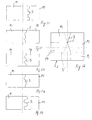
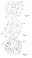
- a magnet structure of a Nuclear Magnetic Resonance imaging apparatus has two opposing pole pieces, generally denoted 1, between which a static magnetic field is generated.
- Each pole piece is composed of magnetic field generating means, here a layer of magnetized material, denoted 101, a magnetically permeable layer laying over the face thereof turned toward the opposite pole piece, e.g. a ferromagnetic layer, or the like.
- Said layer is in turn composed of a massive layer, denoted 201, an additional layer 301 further laying over it, which layer consists of superimposed magnetically permeable sheets or foils 1, which form a pack of sheets, pressed tightly together.
- the pole pieces are supported and/or enclosed by a structure, also made of a magnetically permeable material, which has the additional function of closing the magnetic field between the pole pieces, which structure or yoke is generally denoted 3.
- a structure also made of a magnetically permeable material, which has the additional function of closing the magnetic field between the pole pieces, which structure or yoke is generally denoted 3.
- the structure that is shown in Fig. 19 is a typical structure having an inverted U or C shape. However, the architecture of the structure is not relevant for the purpose of this invention, which applies to the pole pieces of any magnet structure.
- the layer 301 is formed by alternate superimposed sheets 2, 2', each having a number of cuts 102, 102', arranged in various patterns over the sheet surface.
- the invention provides identical sheets, each having different arrangement patterns on the two halves 202, 302 of its surface, and such that, by laying one sheet 2 of the pack of sheets over an identical sheet, after overturning it, as if by leafing through a book, the cuts 102 of the sheets 2 that form the pack of sheets 301 are not coincident, except for one possible, tolerable intersection point.
- underlying sheets do not adhere by their front face against the rear face of the sheet lying over them, but are overturned, with the front face turned toward the front face of the underlying sheet and adhering against it.
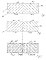
- Fig. 1 shows a first embodiment of the cut arrangement pattern.
- the cuts 102 on one of the two halves 202 of the sheet 2 are oriented to form a set of equally spaced, parallel axes, having a predetermined inclination with respect to a general overturning axis of the sheet 2, here conveniently shown coincident with the center axis.
- the pattern of cuts 102' is not only rotationally symmetric as regards the inclination of the set of parallel axes, but the set of parallel axes is offset along the central overturning axis to a predetermined extent, which may be equal to half the distance between two parallel axes.
- the pack is formed as follows:
- the pack of sheets that forms the layer 301 is formed by an alternation of sheets 2, having a position like that shown in Fig. 1 and sheets 2', having the overturned position as shown in Fig. 2.
- the pack of sheets is thereby easily formed.
- the pack is formed by superimposing several sheets 2, 2' having the same pattern of cuts 102, alternately in the two positions described above, i.e. with the front face turned toward the pack and with the front face turned in the direction opposite to the pack.
- Figure 20 is a simplified and enlarged sectional view of a pack of sheets 2, 2'
- the cuts 102, 102' are disposed on each sheet in an offset position with respect to those of the preceding sheet. Any sheet laid over the pack will have cuts 102 offset with respect to those of the directly underlying sheet 2' but coincident with those of the sheet 2 underlying said directly underlying sheet in the pack of sheets.
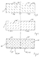
- Figs. 4 to 6 show a first variant embodiment, wherein the cut arrangement pattern is different from the embodiment of the previous Figures 1 to 3.
- the cuts 102 and the cuts 102' are oriented in two transverse, non parallel directions.
- the cuts 102 of the sheets may have a limited and predetermined length, there being provided, like in the embodiment of Figs. 1 to 3, a row of cuts aligned along one or more or all axes of the set of parallel axes, which defines the cut arrangement. Hence, the cuts have a limited length and are separated by cut-free regions 402.
- the arrangement pattern selected for the two halves of the sheet 2 may also include cut-free regions and, besides combining the cut arrangement patterns, it may include offset cut-free regions for the cuts of two adjacent sheets 2, like in the embodiment of Figs. 1 to 3.
- the sheets 2 are coated with a layer of insulating varnish, denoted 4, which additionally has the function of an adhesive to bond together the sheets 2, 2' of the pack. Therefore, the sheets 2, 2' are varnished before being superimposed to form the pack as described above, and then the pack is pressed.
- the sheets may advantageously have centering or alignment holes for the insertion of centering or alignment pins (not shown in detail).
- the pack of sheets may be formed separately and fitted onto the massive layer 201 of the pole pieces 1 or the pack may be formed directly on the massive layer 201 of the pole pieces 1, which has, in this case, a supporting function and may have centering and/or alignment pins or centering and alignment holes for the insertion of said pins.
- the pack may be hot or cold pressed.
- a layer of glue is used instead of the varnish.
- the layer of glue may be provided as adhesive films or may be applied, for instance spread, sprayed or the like, on the face of at least one sheet (2, 2'). After superimposing the sheets, the latter may be hot or cold pressed.
- thermosetting adhesive layer is disposed between the sheets.
- This layer may be provided as a film, or applied by spreading, brushing, spraying, etc.
- a suitable material is, for instance, the material named PRGEP84, type 1080, sold by DRITRON SPA, whose characteristics are listed in www.ditronlaminati.com.
- the cut-free regions 102 which separate the cuts aligned on the same axis are coincident with the cuts 102' of the adjacent sheet 2, and the cuts 102 of the underlying sheet never intersect the cuts 102' of the directly adjacent, underlying sheet.
- the cuts 102 of two adjacent sheets are oriented in transverse, particularly orthogonal directions.
- Figs. 7 to 12 show, like the previous embodiments, two variants of a further embodiment of the sheets.
- the sheets are ideally divided into two halves, preferably symmetrically to a central overturning axis, the patterns of cuts 102 being formed or simply positioned in different manners on the two halves so that cuts are offset when the pack of sheets is formed, by placing the sheets alternately in one position and in an overturned position according to said axis.
- the regions 202 and 302 of the sheets 2, 2' are divided by cuts oriented along two sets of parallel axes, the directions of the axes of the two sets being transverse, particularly perpendicular.
- the cuts are not continuous but broken at intersections.
- the sheet is divided by a grid of cuts 102 into a plurality of adjacent polygonal, particularly square portions, separated by the cuts and joined together by bridges of material at the corners of squares, as designated by 402.
- the difference between the cut arrangements of the two halves 202 and 302 of the sheets is obtained by offsetting the position of the grid of cuts 102 to a predetermined extent along both directions of the sets of cut positioning axes.
- the cuts may be also completed at corners, where the bridges of materials 402 are provided. If these bridges are sufficiently small, they may be cut off even with the pack of sheets in the assembled condition. This operation, that may be performed, for instance, by laser cutting, causes the full separation of the polygonal portions. However, the hole that cuts off the bridges of material between polygonal portions in one sheet, produces a hole in the material of the polygonal portion coincident with the bridge of material 402. This hole causes no operation problem.
- Figs. 10 to 12 differs from the previous embodiment in that the pattern on the portion 302 of the sheet 2 is not obtained by simply translating the pattern of the portion 202 in two perpendicular directions. So, no grid is formed like in the portion 302, but the cuts, having different, particularly perpendicular directions, are disposed in two perpendicular directions and in such positions as to intersect.
- the final pattern of cuts in the superimposed condition is not different from the one of the embodiment as shown in Figures 7 to 9, however the cut arrangement is different at least for the portion 302 of the sheet.
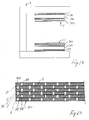
- Figs. 13 to 15 show a further embodiment, wherein the cuts 102 extend radially from the center of the plan view of the sheets 2.
- each cut 102 may be formed discontinuously, i.e. consisting of a row of limited-length cuts, separated by bridges of material, along each radius.
- Two radial sets of cuts may be also provided, a first set extending, with continuous or discontinuous cuts, to a certain distance from the periphery, and a second radial set, angularly interleaved with the former, forming a ring of peripheral cuts, which extend from the end of the first set of cuts to the peripheral portion of the sheet.
- the radial cuts of the peripheral set may be also arranged to start closer to the center as compared with the outer radial end of the cuts of the first set.
- the two halves 202 and 302 of the sheet 2 have radially oriented, angularly equally spaced cuts.
- the angular pitch of the individual cut positioning radiuses is of 20°.
- Such angular distance is maintained for all cuts, except the cuts immediately adjacent to the ideal line that divides the sheets into the two halves 202 and 302.
- the cuts of the half 302 are all rotated by 10° forward with respect to the last adjacent cut 102 on the first sheet half 202.
- the resulting sheet is as shown in Figures 13 and 14, i.e. by using the same sheet pack forming arrangements, an angular offset is provided between the radial cuts of the underlying sheet and the sheet laying over the latter in an overturned position.
- the advantage as regards construction consists in that the sheet is not required to be rotated, but simply has to be overturned before laying it over the top sheet of the pack. In order to cause the cuts to be offset, no mutual rotation of the sheets is required, which would be only possible by using circular sheets.
- the cuts are properly offset by simply alternately overturning the sheets as they are placed on the pack being formed, and fitting them onto the centering pins.
- Figs. 16 and 17 show another advantageous feature, that may be provided in combination with any sheet described in the previous embodiments of Figures 1 to 15.
- cut arrangement patterns have been omitted from the sheets.
- each sheet 2, 2' may be composed of two parts P1, P2 separated along a predetermined parting line, which parting line is in such position and has such an orientation relative to the peripheral shape of the sheets that, as the sheets are stacked in alternately overturned positions, as described in greater detail above, the parting lines between the two sheet parts are disposed in non coincident positions and/or in such a manner as to avoid or minimize intersections.
- the parting line is selected in such position and with such an orientation as to coincide neither with the center sheet overturning axis and/or with a center axis parallel to an overturning axis, nor with a cut 102, 102' positioning axis.
- Figure 16 shows two superimposed sheets 2 and 2', one in a first position and the other in a second position, the latter corresponding to an overturned superimposed position of said second sheet 2' on the former 2.
- the parting line 5 is eccentric to the center overturning axis, which is outlined by a dashed line.
- the eccentric parting line 5 of the sheet 2 is not coincident with the parting line 5 of the overturned sheet 2', whereby the pack of sheets is not divided, along a perpendicular plane of the pack of sheets, into two packs of sheets, continuously extending through the pack.
- Figure 16 may be improved by providing sheets separated into three or more parts, either in one direction or in both directions.
- Fig. 17 shows an example of arrangement of parting lines in a sheet composed of four parts, by providing a complex and branched parting line 5.
- a minimum number of intersections cannot be avoided, particularly the point denoted C.
- the dotted line, denoted 5' outlines the combined parting line obtained in the overturned and superimposed sheet, whereas the dashed lines outline the two center orthogonal axes, referred to the plan view of the whole sheet.
- the whole sheet 2 is composed in this case by four smaller parts P1, P2, P3, P4.
- the above mentioned intersections, and in this specific case the point C are such as to generate a point-like slot in the pack of sheets, which continuously extends across the whole pack. This drawback does not affect significantly the suppression or drastic reduction of undesired currents produced in the pole pieces.
- the advantage of this embodiment consists in that it allows to design relatively inexpensive magnetic structures which are not subjected to the size restrictions imposed by metal sheet manufacturers. It shall be considered that, while these construction parts are relatively large and not complex from the mechanical point of view, the use thereof in Nuclear Magnetic Resonance Imaging apparatuses requires size tolerances that are unusual for the field of metal production. Also, the material used for the sheets is often a special alloy that is never available in the large sizes required by Magnetic Resonance Imaging apparatus manufacturers. The provision of sheets composed of at least two or more parts also allows to use special materials, without forcing the Magnetic Resonance Imaging apparatus manufacturer to require special, high cost productions.
- Figure 18 shows an improvement of the principle as shown in Figs. 16 and 17.
- the parting line 5 is not straight but may have either a rounded or a polygonal profile. Particularly, it has at least two partial segments which form a certain angle. This provides a certain simplified mutual centering and alignment action between the two sheet parts separated by said line 5.
- the sheets may be composed of three or more parts.
- the non-straight parting line may have several different profiles, e.g. a sinusoidal profile or a toothed profile, with square, triangular, rounded, circular teeth, etc. still considering that the envelope of the parting line shall always preferably occupy a surface band not coincident with the center overturning axis or with the center axis parallel to the overturning axis, but possibly intersecting the cuts or partly coincident with a cut.
- Figures 21 to 25 show a few non limiting examples of different possible embodiments of the parting line.
- the dashed line is the center axis of the sheet, parallel to or coincident with the overturning axis of the sheets for forming the pack according to this invention.
- FIGS 26 to 28 a further embodiment of the sheets for the magnet structure according to the invention are shown.
- two kind of sheets provided with a pattern of passing through cuts are provided.
- the sheets has been given the same numeral as in the figures 1 to 4, namely 2, 2'.
- each sheet 2, 2' is provided with an identical pattern of cuts 102.
- the sheets are not provided for being superimposed by turning them upside and downside for each layer but two sheets 2, 2' are provided having the identical and congruent peripheral shape and having an identical pattern of cuts 102 which patter has a different position relatively to the sheet shape.
- the pattern of cuts on sheet 2' is provided on the said sheets 2' in a shifted way with respect to the position of the same pattern of cuts provided on the first sheet 2, according to two directions which are transverse one with respect to the other, particularly orthogonal one to the other and which are parallel to the plane defined by the sheet.
- the cuts of the pattern of the two sheets will not coincide and will be provided laterally staggered relatively to one another as illustrated in figure 28.
- the pack of sheets will never show coincident cuts 102, 102' of two adjacent sheets.
- a circular peripheral shape of the sheets is not mandatory, if the said shape of the sheets has not a rotational symmetry, the alignment of the sheets in the pack can be made by referring g to the shape of the peripheral borders.
- the symmetry of the of the sheets is a rotational one it is preferred to provide both first and second kind of sheets 2, 2' with identical pattern of centering through holes 502 which pattern have the same position for both kind of sheets 2, 2' and fall congruent when the sheets are superimposed. This helps in correctly aligning and orienting the two kind of sheets in order to avoid crossing of the cuts 102, 102' of the two kind of sheets.
- the present example shows a particular pattern which is formed by providing concentric squares paths having a constant length increase from one square to the other inscribed within a circular peripheral edge of the sheets.
- the concentric squares have a common center which is displaced according to two directions relatively to the center of the circular shape of a first sheet kind 2 while the center of the concentric squares are displaced in the same two directions but on the opposite side of the centre of the circular sheet on the second kind of sheets 2'. Cuts are provided along the sides of the concentric squares, the cuts being discontinuous in order to form material connetions between the surface of the sheet enclosed by the cuts on a square path and the material of the sheet outside the said square path.
- the said embodiment could be also designed in order to be obtained by only one kind of sheet having a different positioning of the pattern of cuts onto different halves, whereby the pattern of cuts is identical for both halves of the sheet but the one on a first half is shifted along two orthogonal directions on the other half with respect of the position of the pattern of cut on the first half.
- Providing different kinds of sheets with shifted pattern of cuts according to the above described example of figures 26 to 28 gives the opportunity to increase the number of kinds of sheets.
- a sequence of N different sheets with N integer can be provided each one having an identical pattern of cuts which for each one of the N sheets has been displaced for a given distance along the same two directions relatively to the preceding sheet in the sequence of sheets.
- N can be a rational fraction of the total number of sheets needed for forming the pack of sheets thus an alternate superimposing of the N different kind of sheets in the pack corresponding to a recursive superimposing of the sequence of sheets is needed.
- N can be also equal to the total number of sheets provided in the pack of sheets so that non repetition of the sequence of the N different kind of sheets is needed for forming the pack of sheets.
Landscapes
- Physics & Mathematics (AREA)
- Condensed Matter Physics & Semiconductors (AREA)
- General Physics & Mathematics (AREA)
- Magnetic Resonance Imaging Apparatus (AREA)
- Toys (AREA)
- Magnetic Treatment Devices (AREA)
Applications Claiming Priority (2)
| Application Number | Priority Date | Filing Date | Title |
|---|---|---|---|
| ITSV20030011 | 2003-03-31 | ||
| IT000011A ITSV20030011A1 (it) | 2003-03-31 | 2003-03-31 | Struttura magnetica per macchine di acquisiszione di |
Publications (2)
| Publication Number | Publication Date |
|---|---|
| EP1464977A1 true EP1464977A1 (de) | 2004-10-06 |
| EP1464977B1 EP1464977B1 (de) | 2019-04-17 |
Family
ID=32843926
Family Applications (1)
| Application Number | Title | Priority Date | Filing Date |
|---|---|---|---|
| EP04100369.0A Expired - Lifetime EP1464977B1 (de) | 2003-03-31 | 2004-02-02 | Struktur eines Magneten für Kernspintomographen |
Country Status (3)
| Country | Link |
|---|---|
| US (2) | US7158000B2 (de) |
| EP (1) | EP1464977B1 (de) |
| IT (1) | ITSV20030011A1 (de) |
Families Citing this family (3)
| Publication number | Priority date | Publication date | Assignee | Title |
|---|---|---|---|---|
| ITSV20030011A1 (it) * | 2003-03-31 | 2004-10-01 | Esaote Spa | Struttura magnetica per macchine di acquisiszione di |
| DE102008009734B4 (de) * | 2008-02-19 | 2010-09-16 | Mad Magnetic Drive Ag | Permanentmagnet und Drehlager mit solchen Permanentmagneten |
| GB2559309B (en) * | 2015-11-06 | 2021-09-15 | Synaptive Medical Inc | Electromagnet current constraints |
Citations (4)
| Publication number | Priority date | Publication date | Assignee | Title |
|---|---|---|---|---|
| JPH02184002A (ja) * | 1989-01-10 | 1990-07-18 | Sumitomo Special Metals Co Ltd | Mri用磁界発生装置 |
| US5317297A (en) * | 1990-07-02 | 1994-05-31 | The Regents Of The University Of California | MRI magnet with robust laminated magnetic circuit member and method of making same |
| US5555251A (en) * | 1993-06-08 | 1996-09-10 | Picker Nordstar Inc. | Arrangement to minimize eddy currents in MR imagers |
| EP0984461A2 (de) * | 1998-08-31 | 2000-03-08 | General Electric Company | Magnetpolfläche mit niedrigen Wirbelströmen und reduzierter Hysterese in Magnetresonanzabbildungsverfahren |
Family Cites Families (9)
| Publication number | Priority date | Publication date | Assignee | Title |
|---|---|---|---|---|
| JPS63241905A (ja) * | 1987-03-27 | 1988-10-07 | Sumitomo Special Metals Co Ltd | 磁界発生装置 |
| US4980641A (en) * | 1989-08-11 | 1990-12-25 | General Atomics | Method and apparatus of reducing magnetic hysteresis in MRI systems |
| SG43224A1 (en) * | 1990-09-29 | 1997-10-17 | Sumitomo Spec Metals | Magnetic field generating device used for MRI |
| US5124651A (en) * | 1990-10-24 | 1992-06-23 | Fonar Corporation | Nuclear magnetic resonance scanners with composite pole facings |
| US5680046A (en) * | 1994-08-05 | 1997-10-21 | General Electric Company | Double-sided RF shield for RF coil contained within gradient coils used in high speed NMR imaging |
| DE19854483B4 (de) * | 1998-11-25 | 2005-02-24 | Siemens Ag | Vorrichtung zur Erzeugung eines Magnetfeldes in einem Luftspalt |
| ITSV20000023A1 (it) * | 2000-06-15 | 2001-12-15 | Esaote Spa | Procedimento per la realizzazione di dispositivi di generazione di campi magnetici nelle macchine per il rilevamento di immagini in risonanz |
| ITSV20030011A1 (it) * | 2003-03-31 | 2004-10-01 | Esaote Spa | Struttura magnetica per macchine di acquisiszione di |
| DE102005033989B4 (de) * | 2005-07-21 | 2008-07-10 | Bruker Biospin Ag | Kernspinresonanzapparatur mit Gradientenabschirmanordnung mit reduzierter Kopplung zum Resonatorsystem |
-
2003
- 2003-03-31 IT IT000011A patent/ITSV20030011A1/it unknown
-
2004
- 2004-02-02 EP EP04100369.0A patent/EP1464977B1/de not_active Expired - Lifetime
- 2004-03-31 US US10/813,262 patent/US7158000B2/en not_active Expired - Lifetime
-
2006
- 2006-05-27 US US11/420,740 patent/US7772949B2/en active Active
Patent Citations (4)
| Publication number | Priority date | Publication date | Assignee | Title |
|---|---|---|---|---|
| JPH02184002A (ja) * | 1989-01-10 | 1990-07-18 | Sumitomo Special Metals Co Ltd | Mri用磁界発生装置 |
| US5317297A (en) * | 1990-07-02 | 1994-05-31 | The Regents Of The University Of California | MRI magnet with robust laminated magnetic circuit member and method of making same |
| US5555251A (en) * | 1993-06-08 | 1996-09-10 | Picker Nordstar Inc. | Arrangement to minimize eddy currents in MR imagers |
| EP0984461A2 (de) * | 1998-08-31 | 2000-03-08 | General Electric Company | Magnetpolfläche mit niedrigen Wirbelströmen und reduzierter Hysterese in Magnetresonanzabbildungsverfahren |
Non-Patent Citations (1)
| Title |
|---|
| PATENT ABSTRACTS OF JAPAN vol. 014, no. 457 (E - 0986) 2 October 1990 (1990-10-02) * |
Also Published As
| Publication number | Publication date |
|---|---|
| US20040263301A1 (en) | 2004-12-30 |
| US7772949B2 (en) | 2010-08-10 |
| EP1464977B1 (de) | 2019-04-17 |
| US20060267334A1 (en) | 2006-11-30 |
| US7158000B2 (en) | 2007-01-02 |
| ITSV20030011A1 (it) | 2004-10-01 |
Similar Documents
| Publication | Publication Date | Title |
|---|---|---|
| US20020021129A1 (en) | Method of making a pole piece for an MRI | |
| CN111696766B (zh) | 线圈部件 | |
| US20050029899A1 (en) | Synchronous axial field electrical machine | |
| JP2007285774A (ja) | 磁気レゾルバ及びその製造方法 | |
| US7772949B2 (en) | Magnet structure for nuclear magnetic resonance imaging apparatus | |
| US12051531B2 (en) | Coil component and its manufacturing method | |
| WO2022124415A1 (ja) | レゾルバ | |
| ES2359117T3 (es) | Procedimiento de fabricación de piezas polares de imanes de formación de imágenes por resonancia magnética nuclear. | |
| CN101346873B (zh) | 磁性解算器 | |
| JPH07192921A (ja) | 積層型電子部品 | |
| JP3982593B2 (ja) | 多極磁石の製造方法 | |
| JP4627853B2 (ja) | リラクタンス型電動機 | |
| US20060226726A1 (en) | Planar electromagnetic induction generators and methods | |
| JPH0750866Y2 (ja) | ブラシレスモータ用ステータ | |
| JP7718382B2 (ja) | インダクタ部品 | |
| JP7803247B2 (ja) | インダクタ部品 | |
| JPH0354808A (ja) | 積層型インダクタンス部品 | |
| JP2025121659A (ja) | 電子部品及びその製造方法 | |
| WO2024252915A1 (ja) | 電子部品及びこれを備える回路モジュール | |
| JP2003324009A (ja) | 磁路形成体、電動機、変圧器、アクチュエータ及び磁路形成体製造方法 | |
| JP6844333B2 (ja) | 積層コイル部品の製造方法 | |
| JP2535072B2 (ja) | 磁気ヘッドの製造方法 | |
| JPS61214762A (ja) | ブラシレスモ−タ用ステ−タ | |
| JP2971123B2 (ja) | 電子部品 | |
| JPH048850B2 (de) |
Legal Events
| Date | Code | Title | Description |
|---|---|---|---|
| PUAI | Public reference made under article 153(3) epc to a published international application that has entered the european phase |
Free format text: ORIGINAL CODE: 0009012 |
|
| AK | Designated contracting states |
Kind code of ref document: A1 Designated state(s): AT BE BG CH CY CZ DE DK EE ES FI FR GB GR HU IE IT LI LU MC NL PT RO SE SI SK TR |
|
| AX | Request for extension of the european patent |
Extension state: AL LT LV MK |
|
| 17P | Request for examination filed |
Effective date: 20040903 |
|
| AKX | Designation fees paid |
Designated state(s): AT BE BG CH CY CZ DE DK EE ES FI FR GB GR HU IE IT LI LU MC NL PT RO SE SI SK TR |
|
| RAP1 | Party data changed (applicant data changed or rights of an application transferred) |
Owner name: ESAOTE S.P.A. |
|
| RAP1 | Party data changed (applicant data changed or rights of an application transferred) |
Owner name: ESAOTE S.P.A. |
|
| RAP1 | Party data changed (applicant data changed or rights of an application transferred) |
Owner name: ESAOTE S.P.A. |
|
| RAP1 | Party data changed (applicant data changed or rights of an application transferred) |
Owner name: ESAOTE S.P.A. |
|
| RAP1 | Party data changed (applicant data changed or rights of an application transferred) |
Owner name: ESAOTE S.P.A. |
|
| 17Q | First examination report despatched |
Effective date: 20151029 |
|
| RAP1 | Party data changed (applicant data changed or rights of an application transferred) |
Owner name: ESAOTE S.P.A. |
|
| STAA | Information on the status of an ep patent application or granted ep patent |
Free format text: STATUS: EXAMINATION IS IN PROGRESS |
|
| GRAP | Despatch of communication of intention to grant a patent |
Free format text: ORIGINAL CODE: EPIDOSNIGR1 |
|
| STAA | Information on the status of an ep patent application or granted ep patent |
Free format text: STATUS: GRANT OF PATENT IS INTENDED |
|
| INTG | Intention to grant announced |
Effective date: 20181126 |
|
| GRAS | Grant fee paid |
Free format text: ORIGINAL CODE: EPIDOSNIGR3 |
|
| GRAA | (expected) grant |
Free format text: ORIGINAL CODE: 0009210 |
|
| STAA | Information on the status of an ep patent application or granted ep patent |
Free format text: STATUS: THE PATENT HAS BEEN GRANTED |
|
| AK | Designated contracting states |
Kind code of ref document: B1 Designated state(s): AT BE BG CH CY CZ DE DK EE ES FI FR GB GR HU IE IT LI LU MC NL PT RO SE SI SK TR |
|
| REG | Reference to a national code |
Ref country code: GB Ref legal event code: FG4D |
|
| REG | Reference to a national code |
Ref country code: CH Ref legal event code: EP |
|
| REG | Reference to a national code |
Ref country code: DE Ref legal event code: R096 Ref document number: 602004053886 Country of ref document: DE |
|
| REG | Reference to a national code |
Ref country code: AT Ref legal event code: REF Ref document number: 1122171 Country of ref document: AT Kind code of ref document: T Effective date: 20190515 Ref country code: IE Ref legal event code: FG4D |
|
| REG | Reference to a national code |
Ref country code: NL Ref legal event code: MP Effective date: 20190417 |
|
| PG25 | Lapsed in a contracting state [announced via postgrant information from national office to epo] |
Ref country code: NL Free format text: LAPSE BECAUSE OF FAILURE TO SUBMIT A TRANSLATION OF THE DESCRIPTION OR TO PAY THE FEE WITHIN THE PRESCRIBED TIME-LIMIT Effective date: 20190417 |
|
| PG25 | Lapsed in a contracting state [announced via postgrant information from national office to epo] |
Ref country code: PT Free format text: LAPSE BECAUSE OF FAILURE TO SUBMIT A TRANSLATION OF THE DESCRIPTION OR TO PAY THE FEE WITHIN THE PRESCRIBED TIME-LIMIT Effective date: 20190819 Ref country code: SE Free format text: LAPSE BECAUSE OF FAILURE TO SUBMIT A TRANSLATION OF THE DESCRIPTION OR TO PAY THE FEE WITHIN THE PRESCRIBED TIME-LIMIT Effective date: 20190417 Ref country code: ES Free format text: LAPSE BECAUSE OF FAILURE TO SUBMIT A TRANSLATION OF THE DESCRIPTION OR TO PAY THE FEE WITHIN THE PRESCRIBED TIME-LIMIT Effective date: 20190417 Ref country code: FI Free format text: LAPSE BECAUSE OF FAILURE TO SUBMIT A TRANSLATION OF THE DESCRIPTION OR TO PAY THE FEE WITHIN THE PRESCRIBED TIME-LIMIT Effective date: 20190417 |
|
| PG25 | Lapsed in a contracting state [announced via postgrant information from national office to epo] |
Ref country code: BG Free format text: LAPSE BECAUSE OF FAILURE TO SUBMIT A TRANSLATION OF THE DESCRIPTION OR TO PAY THE FEE WITHIN THE PRESCRIBED TIME-LIMIT Effective date: 20190717 Ref country code: GR Free format text: LAPSE BECAUSE OF FAILURE TO SUBMIT A TRANSLATION OF THE DESCRIPTION OR TO PAY THE FEE WITHIN THE PRESCRIBED TIME-LIMIT Effective date: 20190718 |
|
| REG | Reference to a national code |
Ref country code: AT Ref legal event code: MK05 Ref document number: 1122171 Country of ref document: AT Kind code of ref document: T Effective date: 20190417 |
|
| REG | Reference to a national code |
Ref country code: DE Ref legal event code: R097 Ref document number: 602004053886 Country of ref document: DE |
|
| PG25 | Lapsed in a contracting state [announced via postgrant information from national office to epo] |
Ref country code: EE Free format text: LAPSE BECAUSE OF FAILURE TO SUBMIT A TRANSLATION OF THE DESCRIPTION OR TO PAY THE FEE WITHIN THE PRESCRIBED TIME-LIMIT Effective date: 20190417 Ref country code: SK Free format text: LAPSE BECAUSE OF FAILURE TO SUBMIT A TRANSLATION OF THE DESCRIPTION OR TO PAY THE FEE WITHIN THE PRESCRIBED TIME-LIMIT Effective date: 20190417 Ref country code: RO Free format text: LAPSE BECAUSE OF FAILURE TO SUBMIT A TRANSLATION OF THE DESCRIPTION OR TO PAY THE FEE WITHIN THE PRESCRIBED TIME-LIMIT Effective date: 20190417 Ref country code: CZ Free format text: LAPSE BECAUSE OF FAILURE TO SUBMIT A TRANSLATION OF THE DESCRIPTION OR TO PAY THE FEE WITHIN THE PRESCRIBED TIME-LIMIT Effective date: 20190417 Ref country code: DK Free format text: LAPSE BECAUSE OF FAILURE TO SUBMIT A TRANSLATION OF THE DESCRIPTION OR TO PAY THE FEE WITHIN THE PRESCRIBED TIME-LIMIT Effective date: 20190417 Ref country code: AT Free format text: LAPSE BECAUSE OF FAILURE TO SUBMIT A TRANSLATION OF THE DESCRIPTION OR TO PAY THE FEE WITHIN THE PRESCRIBED TIME-LIMIT Effective date: 20190417 |
|
| PLBE | No opposition filed within time limit |
Free format text: ORIGINAL CODE: 0009261 |
|
| STAA | Information on the status of an ep patent application or granted ep patent |
Free format text: STATUS: NO OPPOSITION FILED WITHIN TIME LIMIT |
|
| 26N | No opposition filed |
Effective date: 20200120 |
|
| PG25 | Lapsed in a contracting state [announced via postgrant information from national office to epo] |
Ref country code: TR Free format text: LAPSE BECAUSE OF FAILURE TO SUBMIT A TRANSLATION OF THE DESCRIPTION OR TO PAY THE FEE WITHIN THE PRESCRIBED TIME-LIMIT Effective date: 20190417 |
|
| PG25 | Lapsed in a contracting state [announced via postgrant information from national office to epo] |
Ref country code: SI Free format text: LAPSE BECAUSE OF FAILURE TO SUBMIT A TRANSLATION OF THE DESCRIPTION OR TO PAY THE FEE WITHIN THE PRESCRIBED TIME-LIMIT Effective date: 20190417 |
|
| REG | Reference to a national code |
Ref country code: CH Ref legal event code: PL |
|
| GBPC | Gb: european patent ceased through non-payment of renewal fee |
Effective date: 20200202 |
|
| REG | Reference to a national code |
Ref country code: BE Ref legal event code: MM Effective date: 20200229 |
|
| PG25 | Lapsed in a contracting state [announced via postgrant information from national office to epo] |
Ref country code: LU Free format text: LAPSE BECAUSE OF NON-PAYMENT OF DUE FEES Effective date: 20200202 Ref country code: MC Free format text: LAPSE BECAUSE OF FAILURE TO SUBMIT A TRANSLATION OF THE DESCRIPTION OR TO PAY THE FEE WITHIN THE PRESCRIBED TIME-LIMIT Effective date: 20190417 |
|
| PG25 | Lapsed in a contracting state [announced via postgrant information from national office to epo] |
Ref country code: CH Free format text: LAPSE BECAUSE OF NON-PAYMENT OF DUE FEES Effective date: 20200229 Ref country code: LI Free format text: LAPSE BECAUSE OF NON-PAYMENT OF DUE FEES Effective date: 20200229 |
|
| PG25 | Lapsed in a contracting state [announced via postgrant information from national office to epo] |
Ref country code: IE Free format text: LAPSE BECAUSE OF NON-PAYMENT OF DUE FEES Effective date: 20200202 Ref country code: GB Free format text: LAPSE BECAUSE OF NON-PAYMENT OF DUE FEES Effective date: 20200202 Ref country code: FR Free format text: LAPSE BECAUSE OF NON-PAYMENT OF DUE FEES Effective date: 20200229 |
|
| PG25 | Lapsed in a contracting state [announced via postgrant information from national office to epo] |
Ref country code: BE Free format text: LAPSE BECAUSE OF NON-PAYMENT OF DUE FEES Effective date: 20200229 |
|
| PG25 | Lapsed in a contracting state [announced via postgrant information from national office to epo] |
Ref country code: CY Free format text: LAPSE BECAUSE OF FAILURE TO SUBMIT A TRANSLATION OF THE DESCRIPTION OR TO PAY THE FEE WITHIN THE PRESCRIBED TIME-LIMIT Effective date: 20190417 |
|
| PGFP | Annual fee paid to national office [announced via postgrant information from national office to epo] |
Ref country code: IT Payment date: 20221130 Year of fee payment: 20 Ref country code: DE Payment date: 20221206 Year of fee payment: 20 |
|
| P01 | Opt-out of the competence of the unified patent court (upc) registered |
Effective date: 20230426 |
|
| REG | Reference to a national code |
Ref country code: DE Ref legal event code: R071 Ref document number: 602004053886 Country of ref document: DE |