EP1465354A1 - Method and device for synchronization in a wireless ultra wide band data communications system - Google Patents
Method and device for synchronization in a wireless ultra wide band data communications system Download PDFInfo
- Publication number
- EP1465354A1 EP1465354A1 EP03290813A EP03290813A EP1465354A1 EP 1465354 A1 EP1465354 A1 EP 1465354A1 EP 03290813 A EP03290813 A EP 03290813A EP 03290813 A EP03290813 A EP 03290813A EP 1465354 A1 EP1465354 A1 EP 1465354A1
- Authority
- EP
- European Patent Office
- Prior art keywords
- correlation
- fact
- samples
- training sequence
- cross
- Prior art date
- Legal status (The legal status is an assumption and is not a legal conclusion. Google has not performed a legal analysis and makes no representation as to the accuracy of the status listed.)
- Withdrawn
Links
Images



Classifications
-
- H—ELECTRICITY
- H04—ELECTRIC COMMUNICATION TECHNIQUE
- H04B—TRANSMISSION
- H04B1/00—Details of transmission systems, not covered by a single one of groups H04B3/00 - H04B13/00; Details of transmission systems not characterised by the medium used for transmission
- H04B1/69—Spread spectrum techniques
- H04B1/7163—Spread spectrum techniques using impulse radio
- H04B1/7183—Synchronisation
-
- H—ELECTRICITY
- H04—ELECTRIC COMMUNICATION TECHNIQUE
- H04B—TRANSMISSION
- H04B1/00—Details of transmission systems, not covered by a single one of groups H04B3/00 - H04B13/00; Details of transmission systems not characterised by the medium used for transmission
- H04B1/69—Spread spectrum techniques
- H04B2001/6908—Spread spectrum techniques using time hopping
Definitions
- the invention relates in general to sliding correlations, especially used in the field of communications, and more particularly in the Ultra Wide Band (UWB) radio technology, for synchronizing a receiver on an incident signal.
- UWB Ultra Wide Band
- a UWB radio transmits a series of very narrow impulses.
- these impulses can take the form of a single cycle, or monocycle, having pulse widths less than 1 ns.
- These short time-domain impulses transformed into the frequency domain result in the ultra wide band spectrum of UWB radio.
- the information conveyed on the signal can be coded by a pulse position modulation (PPM).
- PPM pulse position modulation
- information coding is performed by altering the timing of the individual pulses. More precisely, the series of impulses is transmitted at a repetition rate of up to several Megahertz. Each pulse is transmitted within a window having a predetermined length (pulse repetition period), for example 50 ns. With respect to a nominal position, the pulse is in a early position or in a late position, which permits to encode a "0" or a "1". It is also possible to encode more than two values by using more than two positions shifted with respect to the nominal position. It is also possible to super impose a modulation of the BPSK type on this position modulation. More generally any modulation can be used.
- the IEEE 802.15.3 MAC standard defines the wireless medium access control specifications for high rate wireless personal area networks (WPAN) in a narrow band radio technology.
- a wireless data communication system for example a wireless personal area network, using the UWB radio technology, and more particularly the way of synchronizing two independent data devices of such a network communicating with each other, one of both devices acting as a coordinator of the network.
- An aim of the invention is to provide an efficient way of implementing a synchronization phase, more particularly but not exclusively, during a coarse synchronization phase between a coordinator of the network and an independent data device.
- Another aim of the invention is to provide a synchronization method which can be implemented in very low cost receivers having receiving buffer of reduced size.
- Said incident signal contains a preamble including a preferably periodic, training sequence having a series of pulses whose polarity and time shifts are defined by respective polarity code and time-hopping code.
- Said method comprises a digital cross-correlation of the received signal with said training sequence, said cross-correlation step including algebraically summing in accordance with said polarity code, windows of said received signal, the starting points of said windows being determined by said time-hopping code.
- Said method comprises also a detection step for detecting the end point of the preamble from the result of said cross-correlation step.
- the size of the windows is the factor that constrains the buffer size used in the reception for storing the received samples.
- said training sequence is periodic and comprises replicas, each of which having a size of N samples and containing L pulses, and each window has a size of N samples
- said digital cross-correlation step is performed iteratively in a block-by-block fashion until a stop criterion is reached, the starting points of two consecutive blocks of correlation being separated by 2N samples.
- said digital cross-correlation step comprises:
- said digital cross-correlation step be performed iteratively in a block-by-block fashion until a stop criterion is reached, the computation of each block being split into M slices which are computed by algebraically summing windows N/M samples long.
- the incident signals may carry information within a superframe or frame structure, each superframe or frame containing said preamble including at least M+1 synchronization slots corresponding respectively to the replicas of the training sequence.
- each synchronization slot may be sufficient or not to test a single slice.
- each slice can be computed using one synchronization slot.
- said digital cross-correlation step is performed iteratively in a block-by-block fashion until a stop criterion is reached, the starting points of two consecutive blocks of correlation being separated by N +N/M samples. And for each iteration said digital cross-correlation step comprises :
- each slice can be computed using several adjacent synchronization slots belonging to several consecutive superframes.
- the method according to the invention comprises preferably after each correlation iteration, a step of comparing the content of the accumulation register with a first predetermined threshold, and said stop criterion comprises
- the detection step comprises a first sub-step of detecting one replica of said training sequence, said first sub-step comprising storing in memory means the position of each peak in the accumulation register as well as its sign.
- the first sub-step can successfully detect any of the replicas of the training sequence, while the object of the synchronization is to provide a receiver with the end point of the preamble, namely the index that identifies the last sample of the last replica of the training sequence.
- the preamble contains an additional flipped last replica of the training sequence and said detection step comprises a second sub-step, also called “alignment”, including sequentially scanning the next replicas until the flipped last one is found.
- scanning a next replica comprises performing a correlation between the next replica and the training sequence, comparing the correlation result with a second predetermined threshold, and if the absolute value of the correlation result exceeds said second threshold, using the sign of the correlation result and the sign of each detected peak to decide whether said next replica is the last one or if the scanning operation must be performed again with the replica following said next replica.
- the invention proposes also an independent data device for wireless data communications system, for example of the WPAN type, more particularly of the "piconet" type.
- Said independent data device comprises
- said training sequence comprises replicas, each of which having a size of N samples and containing L pulses ; each window has a size of N samples ; and said digital cross-correlation means is adapted to perform the cross-correlation step iteratively in a block-by-block fashion until a stop criterion is reached, the starting points of two consecutive blocks of correlation being separated by 2N samples ; said cross-correlation means comprises an accumulation register capable of storing N data, and processing means adapted, for each iteration, to :
- said training sequence comprises at least M+1 replicas, each replica having a size of N samples and containing L pulses, M being a sub-multiple of N greater than or equal to 2 ; said digital cross-correlation means is adapted to perform the cross-correlation step iteratively in a block-by-block fashion until a stop criterion is reached, the computation of each block being split into M slices which are computed by algebraically summing windows N/M samples long.
- the incident signal carries information within a superframe or a frame structure, each superframe or frame containing said preamble including at least M+1 synchronization slots corresponding respectively to the replicas of the training sequence ; and said cross-correlation means is adapted to compute each slice using one synchronization slot.
- said digital cross-correlation means is adapted to perform the cross-correlation step iteratively in a block-by-block fashion until a stop criterion is reached, the starting points of two consecutive blocks of correlation being separated by N +N/M samples ; and said cross-correlation means comprises an accumulation register capable of storing N/M data, and processing means adapted for each iteration, to:
- the incident signal carries information within a superframe or a frame structure, each superframe or frame containing said preamble including at least M+1 synchronization slots corresponding respectively to the replicas of the training sequence ; and said cross-correlation means is adapted to compute each slice using several adjacent synchronization slots belonging to several consecutive superframes.
- said cross-correlation means comprises comparison means for comparing after each correlation iteration, the content of the accumulation register with a first predetermined threshold ; and said stop criterion comprises
- said detection means comprises memory means and storing means for storing in said memory means the position of each peak in the accumulation register as well as its sign.
- the preamble contains an additional flipped last replica of the training sequence
- said detection means comprises scanning means for sequentially scanning the next replicas until the flipped last one is found.
- said scanning means comprises correlation means for performing a correlation between the next replica and the training sequence, comparison means for comparing the correlation result with a second predetermined threshold, and control means for, if the absolute value of the correlation result exceeds said second threshold, using the sign of the correlation result and the sign of each detected peak to decide whether said next replica is the last one or if the scanning operation must be performed again with the replica following said next replica.
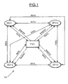
- Figure 1 shows a wireless communication system, such as a wireless personal area network.
- This network of wireless communication system can be organized for example in a so-called piconet PN fashion, which allows a number of independent data devices DEVi to communicate with each other.
- a WPAN can be composed of several piconets.
- a piconet is distinguished from other types of data networks in that communications are normally confined to a person or object that typically covers about 10 meters in all directions and envelops the person or thing whether stationary or in motion.
- a piconet is in contrast to local area network (LAN), metropolitan area network (MAN), and wide area network (WAN) which cover a large geographic area, such as a single building or a campus or that would interconnect facilities in different parts of a country or of the world.
- LAN local area network
- MAN metropolitan area network
- WAN wide area network
- the basic component of a piconet is a data independent device DEV.
- Such an independent data may be for example a personal computer or the like.
- One independent data device DEV is required to assume the role of the piconet coordinator PNC.
- the piconet coordinator PNC provides the basic timing for the piconet with a so-called "beacon” which is a part of a super frame as it will be explained more in details thereafter.
- the PNC can communicate with the independent data devices DEVi. Further, two independent data devices can communicate with each other directly, in a peer to peer manner, without realying through the PNC.
- Figure 2 depicts a super frame structure used in the present invention for the communication between the coordinator PNC and the data devices DEV, as well as for the communication between two independent data devices.
- the incident signal received from a channel by an independent data device DEV carries information within a super frame structure.
- Each super frame SPF i includes several frames FR i respectively allocated to communications between specific pairs of independent data devices DEV.
- each super frame includes a head part, also called beacon, BC.
- the beacon contains a preamble PRB including a periodic training sequence TS1, and a body including time of arrival indication TOA j for each frame FR j .
- each frame FR i includes also a preamble PRB containing a training sequence TS2, and a body part BD containing the useful data.
- an independent data device DEV basically comprises reception means RCM followed by a processor PR.
- reception means comprises antenna ANT means followed by a conventional front end radio frequency stage.
- the processor comprises synchronization means SYM which includes digital cross-correlation means CRM and detection means DM.
- an independent data device DEV When an independent data device DEV is turned on, it will first search for an existing piconet in its neighborhood, and then synchronize to its coordinator PNC. This operation is named “cell synchronization”, or DEV-to-PNC synchronization.
- the cell synchronization operation can be subdivided in three distinct phases :
- the independent data device DEV is looking for the training sequence TS1 sent by the coordinator PNC.
- the object of the digital's coarse synchronization is to provide the independent data device with an index of the sample corresponding to the end of the beacon preamble.
- the independent data device synchronizes precisely to the beginning of the beacon body which contains for example the different indications TOA j , to be sent by the coordinator to all independent data devices DEV of the piconet.
- the clock synchronization consists of identifying an eventual drift between the coordinator's clock and the independent data device clock.
- the end of the beacon preamble will be actually detected.
- a known training sequence TS 1 also called here s(t) is transmitted by the piconet coordinator (PNC).
- PNC piconet coordinator
- a device In order to perform the synchronization with the PNC, a device has to detect such signal in presence of noise and interference, and from this have a timing reference for synchronization.
- the training signal s(t) has the form of a pulsed UWB signal in Equation (1) : Indeed, s ( t ) is a series of L pulses p ( t ), nominally spaced by T f (Pulse Repetition Period : PRP) and whose polarity and time shifts (time-hopping) are defined by the sequences (or codes) a j and c j respectively.
- T c represents the granularity of the time shift (i.e. the minimum separation between two pulse positions, inside a PRP).
- Tc is the time duration between an early pulse and a late pulse, as mentioned above with reference to a nominal position. It is useful to represent s(t) as: where * denotes the linear convolution operator and b ( t ) includes the contributes of the codes a j and c j .
- the received signal r(t) corresponds to s(t) delayed by a certain time ⁇ plus a zero mean gaussian noise process n ( t ) with power equal to ⁇ 2 .
- the detection of the training sequence is based on the cross-correlation of r(t) with the signal s(t) and can be implemented for instance, with an analog matched filter.
- the final goal of synchronization is to have an estimate ⁇ and of the delay ⁇ .
- the synchronization means has access only to samples of the received signal.
- the correlation or matched filter has thus to be implemented digitally by using samples whose sampling frequency is determined by the system.
- the sequences a j and c j are the polarity and time-hopping patterns used in the training sequence.
- the training sequence comprises replicas, each of which having a size of N samples and containing L pulses.
- the training sequence is periodic with a period of N samples.
- the output signal x n is the sum of a signal term y n and a noise term q n :
- the processor PR has to be extremely fast because the result must be achieved and the receiving buffer RB emptied before the arrival of the next block of the received signal.
- the invention proposes a way of implementation which avoids such a disadvantage.
- the invention uses here the periodicity properties of the signal, i.e. the training sequence.
- the matched filtering can be performed in a circular way and the periodic autocorrelation function of b n , (n), appears in the expression of y n . (n) is periodic with a period of N samples and so the correlation process can be performed in a block-by-block fashion, iteratively filtering blocks of N samples of the received signal.
- the received signal r n is split into blocks of N samples.
- a circular correlation with b n is computed and the result is passed to a threshold device. More precisely, for the periodicity properties of the signal, a block circularly shifted of c j samples has the same signal content of a block taken from the received signal, but starting c j samples after. In this way the circular correlation can be computed by using different windows W ( i,j ) / n of the received signal, whose starting points are selected according to the time-shifts c j , as depicted in figure 6.
- the term 2Ni + c j corresponds to the starting times of the windows W ( i,j ) / n of the received signal.
- the starting points of consecutive blocks of correlation are separated by 2 N samples, as depicted in figure 7.
- the sliding correlation algorithm according to this embodiment requires very low complexity for digital data processing: as polarity signaling is used, the weights a j are +/-1 and therefore the whole synchronization algorithm turns out to be the sum (or difference) of windows of the received signal, whose starting points are determined by the time-hopping code used in the training sequence.
- n i 0 identifies the first available sample in the FIFO reception buffer RB (figure 4).
- Each iteration i of the digital cross-correlation phase is performed by processing means PRM (figure 4). Further, the cross-correlation means CRM comprises an accumulation register ACR for storing the value x.
- the cross-correlation CRM further comprises comparison means CMP for comparing the absolute value of x with a first predetermined threshold TH1.
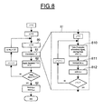
- step 80 the i th correlation iteration 81 is performed.
- this iteration comprises (step 810) taking N samples of the received signal starting from the starting point of the corresponding block increased by the time shift c j of the first pulse.
- said first group is multiplied by the polarity a j of the first pulse (step 811).
- the resulting group of N samples is added (step 812) to the content of said accumulation register.
- the object of the synchronization algorithm is to provide the receiver with the index n synchro of the sample corresponding to the end of the beacon preamble.
- a part of this information is obtained by the correlation means, and more precisely by the position and the sign of a peak detected after comparison with the threshold TH1 (step 82).
- n peak is not sufficient to determine n synchro : the training sequence has been assumed to be periodic with period N and hence n synchro provides information with an ambiguity modulo N .
- the stop criterion comprises also a condition on a maximum number of iterations.
- a single peak is likely to exceed the threshold TH1 only if a single path channel is assumed. In the case of multipath channel, many peaks may exceed the threshold TH1.
- N 1280 samples can be stored in the buffer, corresponding to a training sequence with duration 64 ns sampled at 20 GHz.
- the invention proposes accordingly in the embodiment which will be now described, a slice splitting correlation algorithm.
- the n th sample of the output block is the result of the sum of the n th samples in the windows of the received signal that are summed to get the output block.
- the first N /2 samples of the output block are obtained by just considering the first halves of the windows used previously, and the same happens for the second half of the block.
- the computation of the i th block can be split into two slices, which can be computed by adding weighted windows N /2 samples long.
- x ( i,k ) / n denotes the k th slice of the i th block. From the received signal r n , the slice x ( i,k ) / n can be obtained by combining Equation (8) with Equation (9) :
- Figure 9 describes the relationship between the block x (i) / n and the slices x ( i,k ) / n and how these are obtained from the received signal:
- Equation (10) describes the starting points of the windows to be summed and deserves a more detailed explanation. With the help of figure 9, the meanings of all the contributes are clear:
- the slice splitting procedure can be generalized with more than 2 slices. Generally speaking, a block of N samples can be split into M slices of N / M samples, where M is a sub-multiple of N.
- the slices are defined as follows: And Equation (8) can be modified accordingly:
- Equation (12) describes the starting points of the windows w ( i,k,j ) / n to be summed:
- figure 8 illustrates the flow chart of the sliding correlation according to the invention
- figure 10 illustrates the flow chart of the slice splitting correlation according to the invention.
- steps 100, 101, 102 1010, 1011 and 1012 are analogous to corresponding steps 80, 81, 82, 810, 811 and 812 of figure 8.
- the slice splitting algorithm permits to trade off the complexity of the receiver (in particular the size of the buffer needed in reception) against the duration of the beacon preamble.
- the overall duration of the beacon preamble, N(M+1) samples depends linearly on the number of slices M while the length of the buffer, N / M samples, is inversely proportional to M .
- n peak is affected by an ambiguity modulo N samples, deriving from the fact that the correlation can successfully detect any of the replicas of the training sequence.
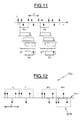
- figure 11 illustrates a case in which a training sequence is replicated 4 times; two possible positions to start the synchronization algorithm are displayed and to both of them corresponds exactly the same correlation output.
- n synchro It must still be determined which one has been detected, in order to provide the value of n synchro .
- any of the replicas of the training sequence are identical, there is no way to determine if the first, the second or the last replica has been detected by the cross-correlation step.
- the detection step which will be now described is independent of the type of correlation used, either sliding or slice-splitting correlation, it is assumed now that the cross-correlation means are adapted to perform a slice-splitting correlation.
- FIG. 12 illustrates the procedure in which LFR designates the last flipped replica of the training sequence TS1.
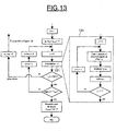
- the detection step according to the invention comprises in fact a first sub-step of detecting one replica of said training sequence, as well as a second sub-step alignment phase including sequentially scanning the next replicas until the flipped last one is found.
- detection means DM comprises scanning means SCM. More precisely, the scanning means comprises correlation means CMX which are adapted in this example, to perform also a slice-splitting correlation, and comparison means CMPX as well as control means CLTM.
- M 1 (no division of the correlation in slices)
- n peak can assume values from 0 up to N while if M >1, n peak can assume values from 0 to N / M. It can be verified that in both cases n peak corresponds to the number of samples that separate the reference point n m assumed in the correlation process and the beginning of the (i+ 1) th replica of training sequence. In this way the receiver is able to align with the beginning of the ( i +1) replica, ( i +2) th , (i+k) th replica and so on, as all the replicas are N samples long.
- the receiver can now evaluate the correlation between the (i+ 1) th replica and the training sequence. In this step it is not necessary to compute a large portion of the full correlation (over a window of N or N / M samples), as the position of the peak is known from the previous cross-correlation step. Therefore only a "zero-shift" correlation is evaluated, by simply adding the samples in the positions prescribed by the pseudo-random code.
- the operation corresponds to a coherent correlation with a rough estimate of the channel impulse response, namely a distance metric calculation.
- replicas of the training sequence are seen as a series of binary symbols (either 'standard' or flipped).
- the object of the alignment is to demodulate these binary symbols and especially correctly find the last one, which is the only one with opposite polarity.
- the aggregated energy of different paths enables to use an even lower threshold in the alignment step.
- the beacon preamble includes at least M+1 synchronization slots SSi corresponding respectively to the replicas of the training sequence. If the signal-to-noise ratio is high enough, each slice can be computed using one synchronization slot. However, in case the actual operating signal to noise ratio is low, one synchronization slot SS may not be sufficient to gather enough energy for taking a decision with the desired degree of accuracy and therefore a longer period of time is required. Without changing the synchronization slot structure it is possible to achieve a better performance, by pairing adjacent synchronization slots SS, and using both of them to test a single slice (figure 15). The energy of the two synchronization slots SS is added, and only after the second synchronization slot SS a decision is taken. In this case, during a period of duration MT train (corresponding to M synchronization slots SS), it is possible to test only M /2 slices, e.g. the first half. Equation (15) is changed into:
- the second half of the slices could be tested in the next M synchronization slots SS. Yet, if the second half of the slices is tested straight afterwards, there could be a missed detection, as during this period there could be a beacon preamble whose correct synchronization is located in the first M /2 slices. Therefore, after the round of M synchronization slots SS, it is necessary to test again the first M /2 slices. Only after a whole superframe period the last M/2 can be tested, throughout the next superframe duration. The worst-case synchronization time is then the duration of two superframes.
- the invention is not limited to the described embodiments. More precisely, although the sliding correlation or the slice splitting correlation have been described for performing a coarse synchronization between the coordinator PNC and an independent data device DEV, the correlations according to the invention can also be used for performing a frame synchronization between two independent data devices communicating with each other, using the training sequence TS2 contained in the preamble PRB of the frame Fr i ( Figure 2).
- the training sequence can be ex ante known by the device or eventually ex ante unknown but belonging to a set of possible training sequences. In such a case, all the training sequences can be successfully tested using the synchronization method accordingly to the invention. And the actual training sequence would be for example the one which leads effectively to a peak of detection.
- flipped last replica can be extended to a pattern of flipped/unflipped training sequence replicas following for instance a Barker code.
- the slice splitting correlation of the invention can be used for performing an cross-correlation of a received signal on blocks of N samples when the size of the receiving buffer is smaller than N.
- the invention proposes also a method for performing a digital cross-correlation of an incident signal containing a periodic training sequence, with said training sequence, said training sequence having M+1 replicas, each replica having a size of N samples and containing L pulses, M being a sub-multiple of N greater than or equal to 2.
- said digital cross-correlation is performed iteratively in a block-by-block fashion, the computation of each block being split into M slices which are computed by algebraically summing windows N/M samples long.
Landscapes
- Engineering & Computer Science (AREA)
- Computer Networks & Wireless Communication (AREA)
- Signal Processing (AREA)
- Synchronisation In Digital Transmission Systems (AREA)
Abstract
Description
- The invention relates in general to sliding correlations, especially used in the field of communications, and more particularly in the Ultra Wide Band (UWB) radio technology, for synchronizing a receiver on an incident signal.
- An application of the invention is for example the wireless personal area networks (WPAN) which are used to convey information over a relatively short distance among a relatively few participants.
- An example of the wireless personal area network is a so-called "piconet" which is a wireless data communications system which allows a number of independent data devices to communicate with each other. A "piconet" is distinguished from other types of data networks in that communications are normally confined to a person or object that typically covers about 10 meters in all directions and envelops the person or a thing whether stationary or in motion.
- Ultra Wide Band radio technology departs from conventional narrow band radio and spread-spectrum technologies in that the bandwidth of the signal at -10dB is typically greater than 20% of the center frequency.
- Further, instead of transmitting a continuous carrier wave modulated with information or with information combined with a spread code, which determines the bandwidth of the signal, a UWB radio transmits a series of very narrow impulses. For example, these impulses can take the form of a single cycle, or monocycle, having pulse widths less than 1 ns. These short time-domain impulses transformed into the frequency domain result in the ultra wide band spectrum of UWB radio.
- In the UWB radio technology, the information conveyed on the signal, can be coded by a pulse position modulation (PPM). In other words, information coding is performed by altering the timing of the individual pulses. More precisely, the series of impulses is transmitted at a repetition rate of up to several Megahertz. Each pulse is transmitted within a window having a predetermined length (pulse repetition period), for example 50 ns. With respect to a nominal position, the pulse is in a early position or in a late position, which permits to encode a "0" or a "1". It is also possible to encode more than two values by using more than two positions shifted with respect to the nominal position. It is also possible to super impose a modulation of the BPSK type on this position modulation. More generally any modulation can be used.
- The IEEE 802.15.3 MAC standard defines the wireless medium access control specifications for high rate wireless personal area networks (WPAN) in a narrow band radio technology.
- However, up to now, no document defines the specification of a wireless data communication system, for example a wireless personal area network, using the UWB radio technology, and more particularly the way of synchronizing two independent data devices of such a network communicating with each other, one of both devices acting as a coordinator of the network.
- The invention intends to provide a solution to this problem.
- An aim of the invention is to provide an efficient way of implementing a synchronization phase, more particularly but not exclusively, during a coarse synchronization phase between a coordinator of the network and an independent data device.
- In particular, the invention proposes a synchronization method which requires very low complexity for digital data processing.
- Another aim of the invention is to provide a synchronization method which can be implemented in very low cost receivers having receiving buffer of reduced size.
- The invention as claimed proposes a method of synchronizing an independent data device of a wireless data communication system on an incident pulsed signal of the ultra wide band type received from a channel by said independent data device.
- Said incident signal contains a preamble including a preferably periodic, training sequence having a series of pulses whose polarity and time shifts are defined by respective polarity code and time-hopping code.
- Said method comprises a digital cross-correlation of the received signal with said training sequence, said cross-correlation step including algebraically summing in accordance with said polarity code, windows of said received signal, the starting points of said windows being determined by said time-hopping code.
- Said method comprises also a detection step for detecting the end point of the preamble from the result of said cross-correlation step.
- The size of the windows is the factor that constrains the buffer size used in the reception for storing the received samples. According to an embodiment of the invention, in which said training sequence is periodic and comprises replicas, each of which having a size of N samples and containing L pulses, and each window has a size of N samples, said digital cross-correlation step is performed iteratively in a block-by-block fashion until a stop criterion is reached, the starting points of two consecutive blocks of correlation being separated by 2N samples. And for each iteration said digital cross-correlation step comprises:
- - a) initializing the content of an accumulation register capable of storing N data,
- - b) taking a first group of N samples of the received signal starting from the starting point of the corresponding block increased by the time shift of the first pulse,
- - c) multiplying said first group by the polarity of said first pulse,
- - d) adding the resulting group of N samples to the content of said accumulation register, and
- - repeating sub-steps b) to d) for all the L pulses.
-
- However, in some cases, the requirements of the size of the receiving buffer could still be too large for very low cost receivers.
- Accordingly, when the size of the receiving buffer, i.e. the size of the window is smaller than N, it is particularly advantageous that said digital cross-correlation step be performed iteratively in a block-by-block fashion until a stop criterion is reached, the computation of each block being split into M slices which are computed by algebraically summing windows N/M samples long.
- In such a case, the training sequence comprises at least M + 1 replicas, each replica having a size of N samples and containing L pulses, M being a sub-multiple of N greater than or equal to 2.
- The incident signals may carry information within a superframe or frame structure, each superframe or frame containing said preamble including at least M+1 synchronization slots corresponding respectively to the replicas of the training sequence. Depending on the signal-to-noise ratio, one synchronization slot may be sufficient or not to test a single slice.
- In other words, in some cases, especially with a signal-to-noise ratio sufficiently high, each slice can be computed using one synchronization slot.
- In such a case, and according to an embodiment of the invention, said digital cross-correlation step is performed iteratively in a block-by-block fashion until a stop criterion is reached, the starting points of two consecutive blocks of correlation being separated by N +N/M samples. And for each iteration said digital cross-correlation step comprises :
- a) initializing the content of an accumulation register capable of storing N/M data,
- b) taking a first group of N/M samples of the received signal starting from the starting point of the corresponding block increased by the time shift of the first pulse,
- c) multiplying said first group by the polarity of said first pulse,
- d) adding the resulting group of N/M samples to the content of said accumulation register, and
- repeating sub-steps b) to d) for all the L pulses.
- However, when the signal-to-noise ratio is not sufficiently high, each slice can be computed using several adjacent synchronization slots belonging to several consecutive superframes.
- Whatever the case, the method according to the invention comprises preferably after each correlation iteration, a step of comparing the content of the accumulation register with a first predetermined threshold, and said stop criterion comprises
- the detection of at least one sample, called "peak", of said accumulation register having a value greater than said first predetermined threshold, or
- a predetermined maximum number of correlation iterations. The number of peaks that can be detected, depends on the number of relevant paths (with large enough amplitude) of the channel.
- According to an embodiment of the invention, the detection step comprises a first sub-step of detecting one replica of said training sequence, said first sub-step comprising storing in memory means the position of each peak in the accumulation register as well as its sign.
- Once a peak is detected, its position with respect to the correlation window is used to adjust the timing reference to the beginning of the next training sequence replica.
- However, the first sub-step can successfully detect any of the replicas of the training sequence, while the object of the synchronization is to provide a receiver with the end point of the preamble, namely the index that identifies the last sample of the last replica of the training sequence.
- Thus, according to an embodiment of the invention, the preamble contains an additional flipped last replica of the training sequence and said detection step comprises a second sub-step, also called "alignment", including sequentially scanning the next replicas until the flipped last one is found.
- According to an embodiment of the invention, scanning a next replica comprises performing a correlation between the next replica and the training sequence, comparing the correlation result with a second predetermined threshold, and if the absolute value of the correlation result exceeds said second threshold, using the sign of the correlation result and the sign of each detected peak to decide whether said next replica is the last one or if the scanning operation must be performed again with the replica following said next replica.
- The invention proposes also an independent data device for wireless data communications system, for example of the WPAN type, more particularly of the "piconet" type.
- Said independent data device comprises
- reception means for receiving an incident pulsed signal of the ultra wide band type from a channel, said incident signal containing a preamble including a training sequence having a series of pulses whose polarity and time shifts are defined by respective polarity code and time-hopping code, and
- synchronization means comprising :
- digital cross-correlation means for performing a cross-correlation of the received signal with said training sequence, said cross-correlation step including algebraically summing in accordance with said polarity code, windows of said received signal, the starting points of said windows being determined by said time-hopping code, and
- detection means for detecting the end point of the preamble from the result delivered by said cross-correlation means.
- According to an embodiment of the invention, said training sequence comprises replicas, each of which having a size of N samples and containing L pulses ; each window has a size of N samples ; and said digital cross-correlation means is adapted to perform the cross-correlation step iteratively in a block-by-block fashion until a stop criterion is reached, the starting points of two consecutive blocks of correlation being separated by 2N samples ; said cross-correlation means comprises an accumulation register capable of storing N data, and processing means adapted, for each iteration, to :
- a) initialize the content of said accumulation register,
- b) take a first group of N samples of the received signal starting from the starting point of the corresponding block increased by the time shift of the first pulse,
- c) multiply said first group by the polarity of said first pulse,
- d) add the resulting group of N samples to the content of said accumulation register, and
- repeat sub-steps b) to d) for all the L pulses.
- According to another embodiment of the invention, said training sequence comprises at least M+1 replicas, each replica having a size of N samples and containing L pulses, M being a sub-multiple of N greater than or equal to 2 ; said digital cross-correlation means is adapted to perform the cross-correlation step iteratively in a block-by-block fashion until a stop criterion is reached, the computation of each block being split into M slices which are computed by algebraically summing windows N/M samples long.
- According to an embodiment of the invention, the incident signal carries information within a superframe or a frame structure, each superframe or frame containing said preamble including at least M+1 synchronization slots corresponding respectively to the replicas of the training sequence ; and said cross-correlation means is adapted to compute each slice using one synchronization slot.
- According to an embodiment of the invention, said digital cross-correlation means is adapted to perform the cross-correlation step iteratively in a block-by-block fashion until a stop criterion is reached, the starting points of two consecutive blocks of correlation being separated by N +N/M samples ; and said cross-correlation means comprises an accumulation register capable of storing N/M data, and processing means adapted for each iteration, to:
- a) initialize the content of said accumulation register,
- b) take a first group of N/M samples of the received signal starting from the starting point of the corresponding block increased by the time shift of the first pulse,
- c) multiply said first group by the polarity of said first pulse,
- d) add the resulting group of N/M samples to the content of said accumulation register, and
- repeat sub-steps b) to d) for all the L pulses.
- According to an embodiment of the invention, the incident signal carries information within a superframe or a frame structure, each superframe or frame containing said preamble including at least M+1 synchronization slots corresponding respectively to the replicas of the training sequence ; and said cross-correlation means is adapted to compute each slice using several adjacent synchronization slots belonging to several consecutive superframes.
- According to an embodiment of the invention, said cross-correlation means comprises comparison means for comparing after each correlation iteration, the content of the accumulation register with a first predetermined threshold ; and said stop criterion comprises
- the detection of at least one sample, called "peak", of said accumulation register having a value greater than said first predetermined threshold, or
- a predetermined maximum number of correlation iterations.
- According to an embodiment of the invention, said detection means comprises memory means and storing means for storing in said memory means the position of each peak in the accumulation register as well as its sign.
- According to an embodiment of the invention, the preamble contains an additional flipped last replica of the training sequence, and said detection means comprises scanning means for sequentially scanning the next replicas until the flipped last one is found.
- According to an embodiment of the invention, said scanning means comprises correlation means for performing a correlation between the next replica and the training sequence, comparison means for comparing the correlation result with a second predetermined threshold, and control means for, if the absolute value of the correlation result exceeds said second threshold, using the sign of the correlation result and the sign of each detected peak to decide whether said next replica is the last one or if the scanning operation must be performed again with the replica following said next replica.
- Other advantages and features of the invention will appear on examining the detailed description of embodiments, these being in no way limiting and of the appended drawings in which;
- figure 1 shows diagrammatically an architecture of a wireless personal area network according to the invention,
- figure 2 shows diagrammatically an example of a super frame structure,
- figure 3 shows diagrammatically an internal architecture of an independent data device according to the invention,
- figures 4 and 5 show diagrammatically more in details, parts of the independent data device illustrated in figure 3,
- figures 6-8 relate to a first embodiment of a method according to the invention,
- figures 9-11 relate to a second embodiment of a method according to the invention,
- figures 12 and 13 relate more particularly to the alignment step of a method according to the invention, and,
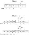
- figures 14 and 15 illustrate diagrammatically two possible ways of computing signal slices in a slice-splitting correlation according to the invention.
- Figure 1 shows a wireless communication system, such as a wireless personal area network. This network of wireless communication system can be organized for example in a so-called piconet PN fashion, which allows a number of independent data devices DEVi to communicate with each other. A WPAN can be composed of several piconets.
- A piconet is distinguished from other types of data networks in that communications are normally confined to a person or object that typically covers about 10 meters in all directions and envelops the person or thing whether stationary or in motion.
- A piconet is in contrast to local area network (LAN), metropolitan area network (MAN), and wide area network (WAN) which cover a large geographic area, such as a single building or a campus or that would interconnect facilities in different parts of a country or of the world.
- The basic component of a piconet is a data independent device DEV. Such an independent data may be for example a personal computer or the like.
- One independent data device DEV is required to assume the role of the piconet coordinator PNC.
- The piconet coordinator PNC provides the basic timing for the piconet with a so-called "beacon" which is a part of a super frame as it will be explained more in details thereafter.
- The PNC can communicate with the independent data devices DEVi. Further, two independent data devices can communicate with each other directly, in a peer to peer manner, without realying through the PNC.
- Figure 2 depicts a super frame structure used in the present invention for the communication between the coordinator PNC and the data devices DEV, as well as for the communication between two independent data devices.
- The incident signal received from a channel by an independent data device DEV carries information within a super frame structure.
- Each super frame SPFi includes several frames FRi respectively allocated to communications between specific pairs of independent data devices DEV.
- Further, each super frame includes a head part, also called beacon, BC. The beacon contains a preamble PRB including a periodic training sequence TS1, and a body including time of arrival indication TOAj for each frame FRj.
- Further, each frame FRi includes also a preamble PRB containing a training sequence TS2, and a body part BD containing the useful data.
- As illustrated in figure 3, an independent data device DEV basically comprises reception means RCM followed by a processor PR.
- More precisely, reception means comprises antenna ANT means followed by a conventional front end radio frequency stage.
- The processor comprises synchronization means SYM which includes digital cross-correlation means CRM and detection means DM.
- The internal architecture of the cross-correlation means CRM and the detection means DM will be described more in details thereafter.
- When an independent data device DEV is turned on, it will first search for an existing piconet in its neighborhood, and then synchronize to its coordinator PNC. This operation is named "cell synchronization", or DEV-to-PNC synchronization.
- The cell synchronization operation can be subdivided in three distinct phases :
- the coarse synchronization,
- the fine synchronization,
- the clock synchronization.
- During the coarse synchronization, the independent data device DEV is looking for the training sequence TS1 sent by the coordinator PNC.
- The object of the digital's coarse synchronization is to provide the independent data device with an index of the sample corresponding to the end of the beacon preamble.
- During the fine synchronization, the independent data device synchronizes precisely to the beginning of the beacon body which contains for example the different indications TOAj, to be sent by the coordinator to all independent data devices DEV of the piconet.
- The clock synchronization consists of identifying an eventual drift between the coordinator's clock and the independent data device clock.
- We will now describe more in details different ways of implementing a coarse synchronization.
- Generally speaking, during a first phase including a digital cross-correlation step, one of the replicas of the periodic training sequence TS1 will be detected.
- Then, during a second phase, the end of the beacon preamble will be actually detected.
In the beacon preamble a knowntraining sequence TS 1, also called here s(t) is transmitted by the piconet coordinator (PNC). In order to perform the synchronization with the PNC, a device has to detect such signal in presence of noise and interference, and from this have a timing reference for synchronization. The training signal s(t) has the form of a pulsed UWB signal in Equation (1) :Indeed, s(t) is a series of L pulses p(t), nominally spaced by Tf (Pulse Repetition Period : PRP) and whose polarity and time shifts (time-hopping) are defined by the sequences (or codes) aj and cj respectively. Tc represents the granularity of the time shift (i.e. the minimum separation between two pulse positions, inside a PRP). In another context, for 2-PPM data modulation, Tc is the time duration between an early pulse and a late pulse, as mentioned above with reference to a nominal position. It is useful to represent s(t) as: where * denotes the linear convolution operator and b(t) includes the contributes of the codes aj and cj .
- It is assumed that the received signal r(t) corresponds to s(t) delayed by a certain time τ plus a zero mean gaussian noise process n(t) with power equal to σ2.
- It is known that the detection of the training sequence is based on the cross-correlation of r(t) with the signal s(t) and can be implemented for instance, with an analog matched filter.
- The final goal of synchronization is to have an estimate τ and of the delay τ.
- However, in the digital UWB radio technology, the synchronization means has access only to samples of the received signal. The correlation or matched filter has thus to be implemented digitally by using samples whose sampling frequency is determined by the system.
The signals are redefined as follows:
- The sequences aj and cj are the polarity and time-hopping patterns used in the training sequence.
- The training sequence comprises replicas, each of which having a size of N samples and containing L pulses. In other words, the training sequence is periodic with a period of N samples.
- The output signal xn is the sum of a signal term yn and a noise term qn :The signal term yn is the following:

- As illustrated in figure 4, the cross-correlation means CRM comprise a receiving buffer RB.
- Theoretically, in order to correctly perform the block-by-block circular correlation, the processor PR has to be extremely fast because the result must be achieved and the receiving buffer RB emptied before the arrival of the next block of the received signal.
- Practically, the invention proposes a way of implementation which avoids such a disadvantage.
- And the invention uses here the periodicity properties of the signal, i.e. the training sequence.
- In this case, the matched filtering can be performed in a circular way and the periodic autocorrelation function of bn,(n), appears in the expression of yn .

- In other words the received signal rn is split into blocks of N samples. At each iteration of the synchronization algorithm one block is received as input, a circular correlation with bn is computed and the result is passed to a threshold device.
More precisely, for the periodicity properties of the signal, a block circularly shifted of cj samples has the same signal content of a block taken from the received signal, but starting cj samples after. In this way the circular correlation can be computed by using different windows W (i,j) / n of the received signal, whose starting points are selected according to the time-shifts cj , as depicted in figure 6. - The ith output block x (i) / n, n = 0,1,..N-1 is obtained as follows:

- The term 2Ni + cj corresponds to the starting times of the windows W (i,j) / n of the received signal. The starting points of consecutive blocks of correlation are separated by 2N samples, as depicted in figure 7. The sliding correlation algorithm according to this embodiment requires very low complexity for digital data processing: as polarity signaling is used, the weights aj are +/-1 and therefore the whole synchronization algorithm turns out to be the sum (or difference) of windows of the received signal, whose starting points are determined by the time-hopping code used in the training sequence.
- The flow chart of the sliding correlation according to this embodiment is also illustrated in figure 8.
- In this figure, it is assumed that ni=0 identifies the first available sample in the FIFO reception buffer RB (figure 4).
- Each iteration i of the digital cross-correlation phase is performed by processing means PRM (figure 4). Further, the cross-correlation means CRM comprises an accumulation register ACR for storing the value x.
- The cross-correlation CRM further comprises comparison means CMP for comparing the absolute value of x with a first predetermined threshold TH1.
- As illustrated in figure 8, after the content of the accumulation register has been initialized to 0 (step 80) the ith correlation iteration 81 is performed.
- More precisely, this iteration comprises (step 810) taking N samples of the received signal starting from the starting point of the corresponding block increased by the time shift cj of the first pulse.
- Then, said first group is multiplied by the polarity aj of the first pulse (step 811).
- The resulting group of N samples is added (step 812) to the content of said accumulation register.
- And these sub-steps are repeated for all the L pulses.
The object of the synchronization algorithm is to provide the receiver with the index nsynchro of the sample corresponding to the end of the beacon preamble. - A part of this information is obtained by the correlation means, and more precisely by the position and the sign of a peak detected after comparison with the threshold TH1 (step 82).
- More precisely, if a peak is successfully detected (the absolute value of a sample of the correlation output is above the threshold), its position npeak and its sign αPeak are stored (step 83) by storing means STM into memory means MM (figure 5). The sign of the peak holds information on the absolute phase of the received signal and is also needed to obtain nsynchro. In fact, npeak is not sufficient to determine nsynchro : the training sequence has been assumed to be periodic with period N and hence nsynchro provides information with an ambiguity modulo N.
- It will be explained more in details thereafter how to solve this ambiguity modulo N.
- In figure 8, it has been assumed that the stop criterion of the outer loop was the obtention of a peak. However, in some cases, the signal-to-noise ratio can be so low that no detection is possible. Another possibility is that no coordinator is transmitting and consequently there is nothing to detect.
- Therefore, it is preferable that the stop criterion comprises also a condition on a maximum number of iterations.
- Further, a single peak is likely to exceed the threshold TH1 only if a single path channel is assumed. In the case of multipath channel, many peaks may exceed the threshold TH1.
- Here (figure 9) and in the following, it is assumed that a single path channel is present.
- The optimization of the algorithm according to the invention with multipath propagation will be treated in details thereafter.
- The main advantage of the embodiment which has been described, is a very low complexity of the control needed for the processing of data. Nevertheless, the requirements of the size of the receiving buffer could still be too large for very low cost receivers.
- More precisely, with the sliding correlation algorithm described above, the ith iteration (or block) of the full correlation is obtained as:

- Namely, the block is the result of the sum of L weighted windows W (i,j) / n of the received signal. The size of such windows is the factor that constrains the minimum buffer size in the reception, which must be able to store N samples. As a numerical example, if the training sequence is 1 µs long, a sampling frequency equal to 20 GHz implies that the buffer in reception must be able to store N = 20000 samples.
- However, according to one possible implementation suitable for very low cost receivers, only N = 1280 samples can be stored in the buffer, corresponding to a training sequence with duration 64 ns sampled at 20 GHz.
- Thus, it is particularly advantageous to reduce the complexity required by the sliding correlation algorithm detailed above.
- The invention proposes accordingly in the embodiment which will be now described, a slice splitting correlation algorithm.
- With respect to how the sliding correlation is performed, it is clear that the nth sample of the output block is the result of the sum of the n th samples in the windows of the received signal that are summed to get the output block.
- Indeed, nothing prevents the algorithm from just computing part of the whole block, for instance the first half. The first N/2 samples of the output block are obtained by just considering the first halves of the windows used previously, and the same happens for the second half of the block. In other words, the computation of the i th block can be split into two slices, which can be computed by adding weighted windows N/2 samples long. The following relationship holds between a block and the corresponding slices :where x (i,k) / n denotes the kth slice of the ith block. From the received signal rn, the slice x (i,k) / n can be obtained by combining Equation (8) with Equation (9) :


- Figure 9 describes the relationship between the block x (i) / n and the slices x (i,k) / n and how these are obtained from the received signal:
- The delay term 3iN + kN + kNl2 + cj in Equation (10) describes the starting points of the windows to be summed and deserves a more detailed explanation. With the help of figure 9, the meanings of all the contributes are clear:
- cj is the time-shift given by the time-hopping code
- kNl2 is needed to properly "align" the slices inside the block
- kN is needed to prevent windows of the same block but of different slices from overlapping
- 3iN is needed to prevent windows of different blocks from overlapping.
- The slice splitting procedure can be generalized with more than 2 slices. Generally speaking, a block of N samples can be split into M slices of N/M samples, where M is a sub-multiple of N. The slices are defined as follows:And Equation (8) can be modified accordingly:


- As before, the delay term i(M+1)N + kN + kN/M + cj in Equation (12) describes the starting points of the windows w (i,k,j) / n to be summed:
- cj is the time-shift given by the time-hopping code
- kNlM is needed to properly "align" the slices inside the block
- kN is needed to prevent windows of the same block but of different slices from overlapping
- i(M+1)N is needed to prevent windows of different blocks from overlapping.
- At this stage, a change of notation is useful: an index m is defined, which combines the index i (block of full correlation) and the index k (slice of the correlation):
- And conversely
As it is well known by the man skilled in the art, the floor function applied to x gives the largest integer less than or equal to x.
With this notation, the starting point of the windows is shifted exactly N + N/M samples at every increment of m.W (m,j) / nis a window of N/M samples, starting at sample nm of rn
- It can be verified that an iteration of the full correlation (m = 0,1,..M-1) does not require more than M + 1 repetitions of the training sequence in the beacon preamble.
- While figure 8 illustrates the flow chart of the sliding correlation according to the invention, figure 10 illustrates the flow chart of the slice splitting correlation according to the invention.
- Except for the number of samples in windows, the steps illustrated in this figure 10 are analogous to those illustrated in figure 8 and will not be described more in details here. More precisely, in figure 10,
steps corresponding steps - The slice splitting algorithm permits to trade off the complexity of the receiver (in particular the size of the buffer needed in reception) against the duration of the beacon preamble. In fact the overall duration of the beacon preamble, N(M+1) samples, depends linearly on the number of slices M while the length of the buffer, N/M samples, is inversely proportional to M.
- As indicated above, either for the sliding correlation of the first embodiment, or the slice splitting correlation of the second embodiment, npeak is affected by an ambiguity modulo N samples, deriving from the fact that the correlation can successfully detect any of the replicas of the training sequence.
- As an example, figure 11 illustrates a case in which a training sequence is replicated 4 times; two possible positions to start the synchronization algorithm are displayed and to both of them corresponds exactly the same correlation output.
- It must still be determined which one has been detected, in order to provide the value of nsynchro .
- However, because any of the replicas of the training sequence are identical, there is no way to determine if the first, the second or the last replica has been detected by the cross-correlation step. Although the detection step which will be now described is independent of the type of correlation used, either sliding or slice-splitting correlation, it is assumed now that the cross-correlation means are adapted to perform a slice-splitting correlation.
- To overcome the problem of ambiguity modulo N samples, an additional replica of the training sequence is inserted just after the M+1 replicas, but flipped. This differentiates it from the other replicas. Figure 12 illustrates the procedure in which LFR designates the last flipped replica of the training sequence TS1.
- All in all, the number of replicas of the training sequence in the beacon preamble is Q = M + 2.
- As indicated above, the detection step according to the invention comprises in fact a first sub-step of detecting one replica of said training sequence, as well as a second sub-step alignment phase including sequentially scanning the next replicas until the flipped last one is found. In this respect, detection means DM (figure 5) comprises scanning means SCM. More precisely, the scanning means comprises correlation means CMX which are adapted in this example, to perform also a slice-splitting correlation, and comparison means CMPX as well as control means CLTM.
- The flow chart of this alignment phase of the detection step, including also a slice-
splitting correlation 131, is illustrated in figure 13. - Let the detected replica be the ith out of Q: the receiver has no knowledge of which is the actual value of i (i = 1,2,..,Q), the only information in its possession is the position of the peak npeak and its sign αpeak, relatively to the i th replica of the training sequence. For M = 1 (no division of the correlation in slices), npeak can assume values from 0 up to N while if M>1, npeak can assume values from 0 to N/M. It can be verified that in both cases npeak corresponds to the number of samples that separate the reference point nm assumed in the correlation process and the beginning of the (i+1)th replica of training sequence. In this way the receiver is able to align with the beginning of the (i+1) replica, (i+2)th, (i+k) th replica and so on, as all the replicas are N samples long.
- The receiver can now evaluate the correlation between the (i+ 1)th replica and the training sequence. In this step it is not necessary to compute a large portion of the full correlation (over a window of N or N/M samples), as the position of the peak is known from the previous cross-correlation step. Therefore only a "zero-shift" correlation is evaluated, by simply adding the samples in the positions prescribed by the pseudo-random code.

- The result z of the process for k = 1 is then checked against a threshold TH2. If the absolute value of z is below the threshold TH2, a false alarm in the first step of the algorithm is assumed to have taken place and the cross-correlation step starts over. If the absolute value of z exceeds the threshold TH2, two cases are possible: if the sign of z is equal to αpeak, the receiver aligns with the (i+2)th replica of the training sequence and applies again the alignment step of the algorithm. On the other hand, if the sign of z is different than αpeak' the receiver becomes aware of being aligned with the Q th and last replica of the training sequence inside the beacon preamble and is then able to synchronize with the end of it.
- After the cross-correlation step of the algorithm there is a fair certainty that the detected peak was not due to a false alarm. Moreover the alignment step of the algorithm is to be performed only a limited number of times and thus false alarms are not likely to happen. Hence, in the alignment step of the algorithm a lower threshold TH2 can be used. This new decision affects only slightly the overall probability of missed detection and false alarm, in a way that is easy to compute. Empirically the threshold TH2 to be used in the alignment step could be such that the probability of false alarm in the decision is on the order of 10-4, namely on the same order of magnitude of the probability of false alarm in the cross-correlation step of the algorithm evaluated over a superframe duration.
- As it has been determined, during the slice splitting correlation steps, when a peak exceeds the threshold, it is not likely to be the only one.
- If multipath propagation is assumed, after the correlation many paths could be detected, each corresponding to a (npeak, αpeak) pair. This is valuable information that can be exploited to increase the performance of the alignment step of the algorithm. In fact, instead of considering only a position for the alignment procedure, the detected paths can be combined in a rake-like fashion. If the number of detected peaks is U, the alignment step of the algorithm computes the correlation value z in this way:

- The operation corresponds to a coherent correlation with a rough estimate of the channel impulse response, namely a distance metric calculation.
- It is to note that the detected paths are not combined according to their estimated amplitude, but are only multiplied by their sign. This is a sub-optimal solution but has the advantage of a lower complexity, with only a slight loss of performance.
- In the multipath case it is not possible to compare the correlation output with the sign of a single peak. In a more correct way the sign of z should be compared with the result of the same correlation operator in Equation (17) on the window of the received signal that originated the detection, namely with the sign of:

- In other words, replicas of the training sequence (convolved with the multipath channel) are seen as a series of binary symbols (either 'standard' or flipped). The object of the alignment is to demodulate these binary symbols and especially correctly find the last one, which is the only one with opposite polarity.
- The aggregated energy of different paths enables to use an even lower threshold in the alignment step.
- As illustrated now in figure 14, the beacon preamble includes at least M+1 synchronization slots SSi corresponding respectively to the replicas of the training sequence. If the signal-to-noise ratio is high enough, each slice can be computed using one synchronization slot. However, in case the actual operating signal to noise ratio is low, one synchronization slot SS may not be sufficient to gather enough energy for taking a decision with the desired degree of accuracy and therefore a longer period of time is required. Without changing the synchronization slot structure it is possible to achieve a better performance, by pairing adjacent synchronization slots SS, and using both of them to test a single slice (figure 15). The energy of the two synchronization slots SS is added, and only after the second synchronization slot SS a decision is taken. In this case, during a period of duration MTtrain (corresponding to M synchronization slots SS), it is possible to test only M/2 slices, e.g. the first half. Equation (15) is changed into:

- The second half of the slices could be tested in the next M synchronization slots SS. Yet, if the second half of the slices is tested straight afterwards, there could be a missed detection, as during this period there could be a beacon preamble whose correct synchronization is located in the first M/2 slices. Therefore, after the round of M synchronization slots SS, it is necessary to test again the first M/2 slices. Only after a whole superframe period the last M/2 can be tested, throughout the next superframe duration. The worst-case synchronization time is then the duration of two superframes.
- The invention is not limited to the described embodiments. More precisely, although the sliding correlation or the slice splitting correlation have been described for performing a coarse synchronization between the coordinator PNC and an independent data device DEV, the correlations according to the invention can also be used for performing a frame synchronization between two independent data devices communicating with each other, using the training sequence TS2 contained in the preamble PRB of the frame Fri (Figure 2).
- Further, the training sequence can be ex ante known by the device or eventually ex ante unknown but belonging to a set of possible training sequences. In such a case, all the training sequences can be successfully tested using the synchronization method accordingly to the invention. And the actual training sequence would be for example the one which leads effectively to a peak of detection.
- And the feature of flipped last replica can be extended to a pattern of flipped/unflipped training sequence replicas following for instance a Barker code.
- Further the above description is an example of application of the patent to a particular network structure with particular superframe structure. However the invention is not limited to this system.
- More generally, the slice splitting correlation of the invention can be used for performing an cross-correlation of a received signal on blocks of N samples when the size of the receiving buffer is smaller than N.
- In other words, the invention proposes also a method for performing a digital cross-correlation of an incident signal containing a periodic training sequence, with said training sequence, said training sequence having M+1 replicas, each replica having a size of N samples and containing L pulses, M being a sub-multiple of N greater than or equal to 2. And said digital cross-correlation is performed iteratively in a block-by-block fashion, the computation of each block being split into M slices which are computed by algebraically summing windows N/M samples long.
Claims (22)
- Method of synchronizing an independent data device (DEV) of a wireless data communications system on an incident pulsed signal of the ultra wide band type received from a channel by said independent data device, said incident signal containing a preamble (PRB) including a training sequence (TS1, TS2) having a series of pulses whose polarity and time shifts are defined by respective polarity code and time-hopping code, said method comprising a digital cross-correlation of the received signal with said training sequence, said cross-correlation step (81, 101) including algebraically summing in accordance with said polarity code (aj), windows of said received signal, the starting points of said windows being determined by said time-hopping code (cj), and a detection step for detecting the end point (nsynchro) of the preamble from the result of said cross-correlation step.
- Method according to claim 1, characterized by the fact said training sequence is periodic and comprises replicas, each of which having a size of N samples and containing L pulses, by the fact that each window has a size of N samples, and by the fact that said digital cross-correlation step (81) is performed iteratively in a block-by-block fashion until a stop criterion is reached, the starting points of two consecutive blocks of correlation being separated by 2N samples, by the fact that for each iteration said digital cross-correlation step comprises:- a) initializing (80) the content of an accumulation register capable of storing N data,- b) taking (810) a first group of N samples of the received signal starting from the starting point of the corresponding block increased by the time shift of the first pulse,- c) multiplying (811) said first group by the polarity of said first pulse,- d) adding (812) the resulting group of N samples to the content of said accumulation register, and- repeating sub-steps b) to d) for all the L pulses.
- Method according to claim 1, characterized by the fact that said training sequence is periodic and comprises at least M+1 replicas, each replica having a size of N samples and containing L pulses, M being a sub-multiple of N greater than or equal to 2, by the fact that said digital cross-correlation step (101) is performed iteratively in a block-by-block fashion until a stop criterion is reached, the computation of each block being split into M slices which are computed by algebraically summing windows N/M samples long.
- Method according to claim 3, characterized by the fact that the incident signal carries information within a superframe structure, each superframe containing said preamble including at least M+1 synchronization slots (SS) corresponding respectively to the replicas of the training sequence, and by the fact that each slice is computed using one synchronization slot.
- Method according to claim 4, characterized by the fact that said digital cross-correlation step (101) is performed iteratively in a block-by-block fashion until a stop criterion is reached, the starting points of two consecutive blocks of correlation being separated by N +N/M samples, by the fact that for each iteration said digital cross-correlation step comprises:a) initializing the content (100) of an accumulation register capable of storing N/M data,b) taking (1010) a first group of N/M samples of the received signal starting from the starting point of the corresponding block increased by the time shift of the first pulse,c) multiplying (1011) said first group by the polarity of said first pulse,d) adding (1012) the resulting group of N/M samples to the content of said accumulation register, andrepeating sub-steps b) to d) for all the L pulses.
- Method according to claim 3, characterized by the fact that the incident signal carries information within a superframe structure, each superframe containing said preamble including at least M+1 synchronization slots corresponding respectively to the replicas of the training sequence, and by the fact that each slice is computed using several adjacent synchronization slots (SS) belonging to several consecutive superframes.
- Method according to any one of claims 2 to 6, characterized by the fact that it comprises after each correlation iteration, a step of comparing the content of the accumulation register with a first predetermined threshold (TH1), and by the fact that said stop criterion comprises the detection of at least one sample, called peak, of said accumulation register having a value greater than said first predetermined threshold, or a predetermined maximum number of correlation iterations.
- Method according to claim 7, characterized by the fact that said detection step comprises a first sub-step of detecting one replica of said training sequence, said first sub-step comprising storing in memory means (MM) the position (npeak) of each peak in the accumulation register (ACR) as well as its sign (apeak).
- Method according to claim 8, characterized by the fact that the preamble contains an additional flipped last replica (LFR) of the training sequence, and by the fact that said detection step comprises a second sub-step including sequentially scanning the next replicas until the flipped last one (LFR) is found.
- Method according to claim 9, characterized by the fact that scanning a next replica comprises performing a correlation (131) between the next replica and the training sequence, comparing the correlation result with a second predetermined threshold (TH2), and if the absolute value of the correlation result exceeds said second threshold, using the sign of the correlation result and the sign of each detected peak to decide whether said next replica is the last one or if the scanning operation must be performed with the replica following said next replica.
- Method according to any one of the preceding claims, characterized by the fact that said wireless data communication system is of the WPAN type, for example organized in "piconet" fashion.
- Independent data device of a wireless data communications system, comprisingreception means (RCM) for receiving an incident pulsed signal of the ultra wide band type from a channel, said incident signal carrying containing a preamble including a training sequence having a series of pulses whose polarity and time shifts are defined by respective polarity code and time-hopping code, andsynchronization means (SYM) comprisingdigital cross-correlation means (CRM) for performing a cross-correlation of the received signal with said training sequence, said cross-correlation step including algebraically summing in accordance with said polarity code, windows of said received signal, the starting points of said windows being determined by said time-hopping code, anddetection means (DM) for detecting the end point of the preamble from the result delivered by said cross-correlation means.
- Device according to claim 12, characterized by the fact said training sequence is periodic and comprises replicas, each of which having a size of N samples and containing L pulses, by the fact that each window has a size of N samples, and by the fact that said digital cross-correlation means (CRM) is adapted to perform the cross-correlation step iteratively in a block-by-block fashion until a stop criterion is reached, the starting points of two consecutive blocks of correlation being separated by 2N samples, by the fact that said cross-correlation means comprises an accumulation register capable of storing N data, and processing means adapted, for each iteration, to:a) initialize the content of said accumulation register,b) take a first group of N samples of the received signal starting from the starting point of the corresponding block increased by the time shift of the first pulse,c) multiply said first group by the polarity of said first pulse,d) add the resulting group of N samples to the content of said accumulation register, andrepeat sub-steps b) to d) for all the L pulses.
- Device according to claim 12, characterized by the fact that said training sequence is periodic and comprises at least M+1 replicas, each replica having a size of N samples and containing L pulses, M being a sub-multiple of N greater than or equal to 2, by the fact that said digital cross-correlation means (CRM) is adapted to perform the cross-correlation step iteratively in a block-by-block fashion until a stop criterion is reached, the computation of each block being split into M slices which are computed by algebraically summing windows N/M samples long.
- Device according to claim 14, characterized by the fact that the incident signal carries information within a superframe structure, each superframe containing said preamble including at least M+1 synchronization slots corresponding respectively to the replicas of the training sequence, and by the fact that said cross-correlation means (CRM) is adapted to compute each slice using one synchronization slot.
- Device according to claim 15, characterized by the fact, by the fact that said digital cross-correlation means (CRM) is adapted to perform the cross-correlation step iteratively in a block-by-block fashion until a stop criterion is reached, the starting points of two consecutive blocks of correlation being separated by N +N/M samples, by the fact that said cross-correlation means comprises an accumulation register capable of storing N/M data, and processing means (PRM) adapted for each iteration, to:a) initialize the content of said accumulation register,b) take a first group of N/M samples of the received signal starting from the starting point of the corresponding block increased by the time shift of the first pulse,c) multiply said first group by the polarity of said first pulse,d) add the resulting group of N/M samples to the content of said accumulation register, andrepeat sub-steps b) to d) for all the L pulses.
- Device according to claim 14, characterized by the fact that the incident signal carries information within a superframe structure, each superframe containing said preamble including at least M+1 synchronization slots corresponding respectively to the replicas of the training sequence, and by the fact that said cross-correlation means (CRM) is adapted to compute each slice using several adjacent synchronization slots belonging to several consecutive superframes.
- Device according to any one of claims 13 to 17, characterized by the fact that said cross-correlation means (CRM) comprises comparison means (CMP) for comparing after each correlation iteration, the content of the accumulation register (ACR) with a first predetermined threshold, and by the fact that said stop criterion comprises the detection of at least one sample, called peak, of said accumulation register having a value greater than said first predetermined threshold, or a predetermined maximum number of correlation iterations.
- Device according to claim 18, characterized by the fact that said detection means (DM) comprises memory means (MM) and storing means (STM) for storing in said memory means the position of each peak in the accumulation register as well as its sign.
- Device according to claim 19, characterized by the fact that the preamble contains an additional flipped last replica (LFR) of the training sequence, and by the fact that said detection means comprises scanning means (SCM) for sequentially scanning the next replicas until the flipped last one is found.
- Device according to claim 20, characterized by the fact that said scanning means comprises correlation means (CMX) for performing a correlation between the next replica and the training sequence, comparison means (CMPX) for comparing the correlation result with a second predetermined threshold, and control means (CTLM) for, if the absolute value of the correlation result exceeds said second threshold, using the sign of the correlation result and the sign of each detected peak to decide whether said next replica is the last one or if the scanning operation must be performed with the replica following said next replica.
- Device according to any one of claims 12 to 21, characterized by the fact that said wireless data communication system is of the WPAN type, for example organized in "piconet" fashion.
Priority Applications (2)
| Application Number | Priority Date | Filing Date | Title |
|---|---|---|---|
| EP03290813A EP1465354A1 (en) | 2003-04-01 | 2003-04-01 | Method and device for synchronization in a wireless ultra wide band data communications system |
| US10/814,824 US7254202B2 (en) | 2003-04-01 | 2004-03-31 | Method of synchronizing an independent data device of a wireless data communications system on an incident pulsed signal of the ultra wide band type, and corresponding independent data device |
Applications Claiming Priority (1)
| Application Number | Priority Date | Filing Date | Title |
|---|---|---|---|
| EP03290813A EP1465354A1 (en) | 2003-04-01 | 2003-04-01 | Method and device for synchronization in a wireless ultra wide band data communications system |
Publications (1)
| Publication Number | Publication Date |
|---|---|
| EP1465354A1 true EP1465354A1 (en) | 2004-10-06 |
Family
ID=32842864
Family Applications (1)
| Application Number | Title | Priority Date | Filing Date |
|---|---|---|---|
| EP03290813A Withdrawn EP1465354A1 (en) | 2003-04-01 | 2003-04-01 | Method and device for synchronization in a wireless ultra wide band data communications system |
Country Status (2)
| Country | Link |
|---|---|
| US (1) | US7254202B2 (en) |
| EP (1) | EP1465354A1 (en) |
Cited By (8)
| Publication number | Priority date | Publication date | Assignee | Title |
|---|---|---|---|---|
| WO2007004003A2 (en) | 2005-06-30 | 2007-01-11 | Spyder Navigations L.L.C. | Recovery techniques for wireless communications networks |
| GB2431832A (en) * | 2005-10-27 | 2007-05-02 | Univ Graz Tech | Multiuser transmitted-reference UWB communications system |
| WO2008114986A2 (en) | 2007-03-16 | 2008-09-25 | Lg Electronics Inc. | In one or more network coexi stable environment, a method for determining whether a specific channel is available or not, a method for receiving a signal for detecting and a method for communicating in coexistence with a different kind of network |
| WO2008139044A1 (en) * | 2007-05-11 | 2008-11-20 | Commissariat A L'energie Atomique | Method for processing a sampled rectified ultra wide band signal |
| CN100502257C (en) * | 2006-10-20 | 2009-06-17 | 北京航空航天大学 | A Method for Suppressing Multi-user Interference in Synchronization of UWB Multiple Access System |
| JP2010521868A (en) * | 2007-03-16 | 2010-06-24 | エルジー エレクトロニクス インコーポレイティド | A method for determining whether or not a specific channel can be used in an environment where one or more networks can coexist, a method for receiving a preamble signal, and a method for performing communication in which different networks coexist |
| WO2010138006A1 (en) * | 2009-05-29 | 2010-12-02 | Motorola, Inc | Method and system for training sequence synchronization in a digital communication network |
| WO2014120685A1 (en) * | 2013-02-04 | 2014-08-07 | Dolby Laboratories Licensing Corporation | Systems and methods for detecting a synchronization code word |
Families Citing this family (14)
| Publication number | Priority date | Publication date | Assignee | Title |
|---|---|---|---|---|
| EP1455461A1 (en) * | 2003-03-03 | 2004-09-08 | STMicroelectronics N.V. | Method for processing ultra wide band signals in wireless system, and corresponding device |
| US7433697B2 (en) * | 2003-10-24 | 2008-10-07 | Broadcom Corporation | Synchronized UWB piconets for Simultaneously Operating Piconet performance |
| JP4428143B2 (en) * | 2004-05-28 | 2010-03-10 | ソニー株式会社 | COMMUNICATION DEVICE, COMMUNICATION METHOD, AND PROGRAM |
| US7403746B2 (en) * | 2005-01-04 | 2008-07-22 | Mitsubishi Electric Research Laboratories, Inc. | Adaptive frame durations for time-hopped impulse radio systems |
| WO2007002252A2 (en) * | 2005-06-22 | 2007-01-04 | Shattil, Steve | Systems and method for generating a common preamble for use in wireless communication system |
| EP2060010A1 (en) * | 2006-08-23 | 2009-05-20 | The Governors Of The University Of Alberta | System and method for receiving time-hopping ultra-wide bandwidths signals |
| US20080112369A1 (en) * | 2006-11-13 | 2008-05-15 | Samsung Electronics Co., Ltd. | Method and apparatus for allocating bandwidth of wireless network, and method and apparatus for transmitting and receiving data on the network |
| US20090190704A1 (en) * | 2008-01-24 | 2009-07-30 | Horizon Semiconductors Ltd. | Synchronization of frame signals having two synchronization words |
| US8457560B2 (en) * | 2009-04-06 | 2013-06-04 | Samsung Electronics Co., Ltd. | Apparatus and method for interference minimization in body area networks using low duty cycle and preamble design |
| US8611474B2 (en) * | 2010-04-23 | 2013-12-17 | Qualcomm Incorporated | System and method for detecting and processing received signal with pulse sequence |
| US9912511B2 (en) | 2016-03-07 | 2018-03-06 | Hong Kong Applied Science And Technology Research Institute Co., Ltd. | Systems and methods for time synchronization between transmitters and receivers in a communication system |
| US9912512B2 (en) | 2016-03-07 | 2018-03-06 | Hong Kong Applied Science And Technology Research Institute Co., Ltd. | Systems and methods for frequency synchronization between transmitters and receivers in a communication system |
| EP3952152A1 (en) * | 2017-03-24 | 2022-02-09 | Cable Television Laboratories, Inc. | System and methods for coherent pon architecture and burst-mode reception |
| CN113346927B (en) * | 2019-11-21 | 2022-12-23 | Oppo广东移动通信有限公司 | A signal synchronization method, device and computer storage medium |
Citations (2)
| Publication number | Priority date | Publication date | Assignee | Title |
|---|---|---|---|---|
| WO2002052740A1 (en) * | 2000-12-22 | 2002-07-04 | Scientific Generics Limited | Timing aid for ultra-wideband system |
| WO2003009608A2 (en) * | 2001-07-19 | 2003-01-30 | Roke Manor Research Limited | Method for synchronising radio terminals in a radio communication system |
Family Cites Families (3)
| Publication number | Priority date | Publication date | Assignee | Title |
|---|---|---|---|---|
| US6463107B1 (en) * | 1999-07-01 | 2002-10-08 | Telefonaktiebolaget Lm Ericsson (Publ) | Methods and apparatuses for synchronization and modulation type detection |
| US20020181407A1 (en) * | 2001-03-28 | 2002-12-05 | Anders Khullar | Link quality control by using time dispersion information |
| US6925131B2 (en) * | 2001-08-03 | 2005-08-02 | Lucent Technologies Inc. | Determining channel characteristics in a wireless communication system that uses multi-element antenna |
-
2003
- 2003-04-01 EP EP03290813A patent/EP1465354A1/en not_active Withdrawn
-
2004
- 2004-03-31 US US10/814,824 patent/US7254202B2/en not_active Expired - Lifetime
Patent Citations (2)
| Publication number | Priority date | Publication date | Assignee | Title |
|---|---|---|---|---|
| WO2002052740A1 (en) * | 2000-12-22 | 2002-07-04 | Scientific Generics Limited | Timing aid for ultra-wideband system |
| WO2003009608A2 (en) * | 2001-07-19 | 2003-01-30 | Roke Manor Research Limited | Method for synchronising radio terminals in a radio communication system |
Non-Patent Citations (1)
| Title |
|---|
| WIN M Z ET AL: "ULTRA-WIDE BANDWIDTH TIME-HOPPING SPREAD-SPECTRUM IMPULSE RADIO FORWIRELESS MULTIPLE-ACCESS COMMUNICATIONS", IEEE TRANSACTIONS ON COMMUNICATIONS, IEEE INC. NEW YORK, US, vol. 48, no. 4, April 2000 (2000-04-01), pages 679 - 691, XP000932191, ISSN: 0090-6778 * |
Cited By (14)
| Publication number | Priority date | Publication date | Assignee | Title |
|---|---|---|---|---|
| EP1897279A4 (en) * | 2005-06-30 | 2012-01-04 | Intellectual Ventures I Llc | Recovery techniques for wireless communications networks |
| WO2007004003A2 (en) | 2005-06-30 | 2007-01-11 | Spyder Navigations L.L.C. | Recovery techniques for wireless communications networks |
| GB2431832A (en) * | 2005-10-27 | 2007-05-02 | Univ Graz Tech | Multiuser transmitted-reference UWB communications system |
| CN100502257C (en) * | 2006-10-20 | 2009-06-17 | 北京航空航天大学 | A Method for Suppressing Multi-user Interference in Synchronization of UWB Multiple Access System |
| WO2008114986A2 (en) | 2007-03-16 | 2008-09-25 | Lg Electronics Inc. | In one or more network coexi stable environment, a method for determining whether a specific channel is available or not, a method for receiving a signal for detecting and a method for communicating in coexistence with a different kind of network |
| EP2135363A4 (en) * | 2007-03-16 | 2010-03-17 | Lg Electronics Inc | In one or more network coexi stable environment, a method for determining whether a specific channel is available or not, a method for receiving a signal for detecting and a method for communicating in coexistence with a different kind of network |
| JP2010521868A (en) * | 2007-03-16 | 2010-06-24 | エルジー エレクトロニクス インコーポレイティド | A method for determining whether or not a specific channel can be used in an environment where one or more networks can coexist, a method for receiving a preamble signal, and a method for performing communication in which different networks coexist |
| WO2008139044A1 (en) * | 2007-05-11 | 2008-11-20 | Commissariat A L'energie Atomique | Method for processing a sampled rectified ultra wide band signal |
| US8238408B2 (en) | 2007-05-11 | 2012-08-07 | Commissariat A L'energie Atomique | Method for processing a sampled rectified ultra wide band signal |
| WO2010138006A1 (en) * | 2009-05-29 | 2010-12-02 | Motorola, Inc | Method and system for training sequence synchronization in a digital communication network |
| GB2483189A (en) * | 2009-05-29 | 2012-02-29 | Motorola Solutions Inc | Method and system for training sequence synchronization in a digital communication network |
| GB2483189B (en) * | 2009-05-29 | 2014-05-07 | Motorola Solutions Inc | Method and system for training sequence synchronization in a digital communication network |
| WO2014120685A1 (en) * | 2013-02-04 | 2014-08-07 | Dolby Laboratories Licensing Corporation | Systems and methods for detecting a synchronization code word |
| US9742554B2 (en) | 2013-02-04 | 2017-08-22 | Dolby Laboratories Licensing Corporation | Systems and methods for detecting a synchronization code word |
Also Published As
| Publication number | Publication date |
|---|---|
| US7254202B2 (en) | 2007-08-07 |
| US20040240597A1 (en) | 2004-12-02 |
Similar Documents
| Publication | Publication Date | Title |
|---|---|---|
| US7254202B2 (en) | Method of synchronizing an independent data device of a wireless data communications system on an incident pulsed signal of the ultra wide band type, and corresponding independent data device | |
| US7542486B2 (en) | Method of processing an incident pulsed UWB signal received by an independent data device of a wireless data communication system of the WPAN type, and corresponding independent data device | |
| US7436876B2 (en) | System and method for fast acquisition of ultra wideband signals | |
| US5440597A (en) | Double dwell maximum likelihood acquisition system with continuous decision making for CDMA and direct spread spectrum system | |
| US7099422B2 (en) | Synchronization of ultra-wideband communications using a transmitted-reference preamble | |
| US5029184A (en) | Low probability of intercept communication system | |
| US20040136439A1 (en) | Methods and systems acquiring impulse signals | |
| Aedudodla et al. | Timing acquisition in ultra-wideband communication systems | |
| US7054349B2 (en) | Method and device for decoding an incident pulse signal of the ultra wideband type, in particular for a wireless communication system | |
| Blázquez et al. | Coarse acquisition for ultra wideband digital receivers | |
| WO1995024778A1 (en) | Spread spectrum alignment repositioning method | |
| RU2733419C1 (en) | Transmitter and receiver and corresponding methods | |
| US7313164B1 (en) | Method and system for switching and detecting PN codes for fast acquisition of burst signal | |
| JP4315659B2 (en) | Ultra-wideband type incident pulse signal pulse detection method and detector | |
| JP2017519468A (en) | Wireless communication | |
| KR100910071B1 (en) | Mode Controller for Signal Acquisition and Tracking in Ultra-Wideband Communication Systems | |
| US9531430B2 (en) | Device and method for determining the arrival time of a UWB signal | |
| Gezici et al. | Two-step time of arrival estimation for pulse-based ultra-wideband systems | |
| US7613257B2 (en) | Synchronizing method for impulse radio network | |
| US11774538B2 (en) | Methods and devices for transmitting a bit sequence and estimating the arrival time of same | |
| Salem et al. | Synchronization using an adaptive early-late algorithm for IR-TH-UWB transmission in multipath scenarios | |
| WO2004079921A2 (en) | Method, system and apparatus for acquiring a received impulse radio signal | |
| CN101651976B (en) | Method and device for detection and synchronization of broadcast channel propagation time interval | |
| CN100420160C (en) | Method and system for receiving ultra-wideband signals using adaptive number of transmission paths | |
| CN100521667C (en) | Method, system and device for acquiring received impulse radio signal |
Legal Events
| Date | Code | Title | Description |
|---|---|---|---|
| PUAI | Public reference made under article 153(3) epc to a published international application that has entered the european phase |
Free format text: ORIGINAL CODE: 0009012 |
|
| AK | Designated contracting states |
Kind code of ref document: A1 Designated state(s): AT BE BG CH CY CZ DE DK EE ES FI FR GB GR HU IE IT LI LU MC NL PT RO SE SI SK TR |
|
| AX | Request for extension of the european patent |
Extension state: AL LT LV MK |
|
| 17P | Request for examination filed |
Effective date: 20050309 |
|
| AKX | Designation fees paid |
Designated state(s): DE FR GB IT |
|
| 17Q | First examination report despatched |
Effective date: 20071008 |
|
| GRAP | Despatch of communication of intention to grant a patent |
Free format text: ORIGINAL CODE: EPIDOSNIGR1 |
|
| GRAS | Grant fee paid |
Free format text: ORIGINAL CODE: EPIDOSNIGR3 |
|
| STAA | Information on the status of an ep patent application or granted ep patent |
Free format text: STATUS: THE APPLICATION IS DEEMED TO BE WITHDRAWN |
|
| 18D | Application deemed to be withdrawn |
Effective date: 20111101 |