EP1466829A1 - Anlage zum Füllen von Ventilsäcken - Google Patents
Anlage zum Füllen von Ventilsäcken Download PDFInfo
- Publication number
- EP1466829A1 EP1466829A1 EP04007033A EP04007033A EP1466829A1 EP 1466829 A1 EP1466829 A1 EP 1466829A1 EP 04007033 A EP04007033 A EP 04007033A EP 04007033 A EP04007033 A EP 04007033A EP 1466829 A1 EP1466829 A1 EP 1466829A1
- Authority
- EP
- European Patent Office
- Prior art keywords
- valve
- sonotrode
- bags
- anvil
- ultrasonic welding
- Prior art date
- Legal status (The legal status is an assumption and is not a legal conclusion. Google has not performed a legal analysis and makes no representation as to the accuracy of the status listed.)
- Granted
Links
Images


Classifications
-
- B—PERFORMING OPERATIONS; TRANSPORTING
- B65—CONVEYING; PACKING; STORING; HANDLING THIN OR FILAMENTARY MATERIAL
- B65B—MACHINES, APPARATUS OR DEVICES FOR, OR METHODS OF, PACKAGING ARTICLES OR MATERIALS; UNPACKING
- B65B51/00—Devices for, or methods of, sealing or securing package folds or closures; Devices for gathering or twisting wrappers, or necks of bags
- B65B51/10—Applying or generating heat or pressure or combinations thereof
- B65B51/22—Applying or generating heat or pressure or combinations thereof by friction or ultrasonic or high-frequency electrical means
- B65B51/225—Applying or generating heat or pressure or combinations thereof by friction or ultrasonic or high-frequency electrical means by ultrasonic welding
-
- B—PERFORMING OPERATIONS; TRANSPORTING
- B29—WORKING OF PLASTICS; WORKING OF SUBSTANCES IN A PLASTIC STATE IN GENERAL
- B29C—SHAPING OR JOINING OF PLASTICS; SHAPING OF MATERIAL IN A PLASTIC STATE, NOT OTHERWISE PROVIDED FOR; AFTER-TREATMENT OF THE SHAPED PRODUCTS, e.g. REPAIRING
- B29C65/00—Joining or sealing of preformed parts, e.g. welding of plastics materials; Apparatus therefor
- B29C65/02—Joining or sealing of preformed parts, e.g. welding of plastics materials; Apparatus therefor by heating, with or without pressure
- B29C65/08—Joining or sealing of preformed parts, e.g. welding of plastics materials; Apparatus therefor by heating, with or without pressure using ultrasonic vibrations
- B29C65/083—Joining or sealing of preformed parts, e.g. welding of plastics materials; Apparatus therefor by heating, with or without pressure using ultrasonic vibrations using a rotary sonotrode or a rotary anvil
- B29C65/085—Joining or sealing of preformed parts, e.g. welding of plastics materials; Apparatus therefor by heating, with or without pressure using ultrasonic vibrations using a rotary sonotrode or a rotary anvil using a rotary sonotrode
-
- B—PERFORMING OPERATIONS; TRANSPORTING
- B29—WORKING OF PLASTICS; WORKING OF SUBSTANCES IN A PLASTIC STATE IN GENERAL
- B29C—SHAPING OR JOINING OF PLASTICS; SHAPING OF MATERIAL IN A PLASTIC STATE, NOT OTHERWISE PROVIDED FOR; AFTER-TREATMENT OF THE SHAPED PRODUCTS, e.g. REPAIRING
- B29C65/00—Joining or sealing of preformed parts, e.g. welding of plastics materials; Apparatus therefor
- B29C65/02—Joining or sealing of preformed parts, e.g. welding of plastics materials; Apparatus therefor by heating, with or without pressure
- B29C65/08—Joining or sealing of preformed parts, e.g. welding of plastics materials; Apparatus therefor by heating, with or without pressure using ultrasonic vibrations
- B29C65/083—Joining or sealing of preformed parts, e.g. welding of plastics materials; Apparatus therefor by heating, with or without pressure using ultrasonic vibrations using a rotary sonotrode or a rotary anvil
- B29C65/086—Joining or sealing of preformed parts, e.g. welding of plastics materials; Apparatus therefor by heating, with or without pressure using ultrasonic vibrations using a rotary sonotrode or a rotary anvil using a rotary anvil
-
- B—PERFORMING OPERATIONS; TRANSPORTING
- B29—WORKING OF PLASTICS; WORKING OF SUBSTANCES IN A PLASTIC STATE IN GENERAL
- B29C—SHAPING OR JOINING OF PLASTICS; SHAPING OF MATERIAL IN A PLASTIC STATE, NOT OTHERWISE PROVIDED FOR; AFTER-TREATMENT OF THE SHAPED PRODUCTS, e.g. REPAIRING
- B29C65/00—Joining or sealing of preformed parts, e.g. welding of plastics materials; Apparatus therefor
- B29C65/02—Joining or sealing of preformed parts, e.g. welding of plastics materials; Apparatus therefor by heating, with or without pressure
- B29C65/08—Joining or sealing of preformed parts, e.g. welding of plastics materials; Apparatus therefor by heating, with or without pressure using ultrasonic vibrations
- B29C65/083—Joining or sealing of preformed parts, e.g. welding of plastics materials; Apparatus therefor by heating, with or without pressure using ultrasonic vibrations using a rotary sonotrode or a rotary anvil
- B29C65/087—Joining or sealing of preformed parts, e.g. welding of plastics materials; Apparatus therefor by heating, with or without pressure using ultrasonic vibrations using a rotary sonotrode or a rotary anvil using both a rotary sonotrode and a rotary anvil
-
- B—PERFORMING OPERATIONS; TRANSPORTING
- B29—WORKING OF PLASTICS; WORKING OF SUBSTANCES IN A PLASTIC STATE IN GENERAL
- B29C—SHAPING OR JOINING OF PLASTICS; SHAPING OF MATERIAL IN A PLASTIC STATE, NOT OTHERWISE PROVIDED FOR; AFTER-TREATMENT OF THE SHAPED PRODUCTS, e.g. REPAIRING
- B29C65/00—Joining or sealing of preformed parts, e.g. welding of plastics materials; Apparatus therefor
- B29C65/78—Means for handling the parts to be joined, e.g. for making containers or hollow articles, e.g. means for handling sheets, plates, web-like materials, tubular articles, hollow articles or elements to be joined therewith; Means for discharging the joined articles from the joining apparatus
- B29C65/7858—Means for handling the parts to be joined, e.g. for making containers or hollow articles, e.g. means for handling sheets, plates, web-like materials, tubular articles, hollow articles or elements to be joined therewith; Means for discharging the joined articles from the joining apparatus characterised by the feeding movement of the parts to be joined
- B29C65/7879—Means for handling the parts to be joined, e.g. for making containers or hollow articles, e.g. means for handling sheets, plates, web-like materials, tubular articles, hollow articles or elements to be joined therewith; Means for discharging the joined articles from the joining apparatus characterised by the feeding movement of the parts to be joined said parts to be joined moving in a closed path, e.g. a rectangular path
- B29C65/7882—Means for handling the parts to be joined, e.g. for making containers or hollow articles, e.g. means for handling sheets, plates, web-like materials, tubular articles, hollow articles or elements to be joined therewith; Means for discharging the joined articles from the joining apparatus characterised by the feeding movement of the parts to be joined said parts to be joined moving in a closed path, e.g. a rectangular path said parts to be joined moving in a circular path
-
- B—PERFORMING OPERATIONS; TRANSPORTING
- B29—WORKING OF PLASTICS; WORKING OF SUBSTANCES IN A PLASTIC STATE IN GENERAL
- B29C—SHAPING OR JOINING OF PLASTICS; SHAPING OF MATERIAL IN A PLASTIC STATE, NOT OTHERWISE PROVIDED FOR; AFTER-TREATMENT OF THE SHAPED PRODUCTS, e.g. REPAIRING
- B29C66/00—General aspects of processes or apparatus for joining preformed parts
- B29C66/01—General aspects dealing with the joint area or with the area to be joined
- B29C66/05—Particular design of joint configurations
- B29C66/10—Particular design of joint configurations particular design of the joint cross-sections
- B29C66/11—Joint cross-sections comprising a single joint-segment, i.e. one of the parts to be joined comprising a single joint-segment in the joint cross-section
- B29C66/112—Single lapped joints
- B29C66/1122—Single lap to lap joints, i.e. overlap joints
-
- B—PERFORMING OPERATIONS; TRANSPORTING
- B29—WORKING OF PLASTICS; WORKING OF SUBSTANCES IN A PLASTIC STATE IN GENERAL
- B29C—SHAPING OR JOINING OF PLASTICS; SHAPING OF MATERIAL IN A PLASTIC STATE, NOT OTHERWISE PROVIDED FOR; AFTER-TREATMENT OF THE SHAPED PRODUCTS, e.g. REPAIRING
- B29C66/00—General aspects of processes or apparatus for joining preformed parts
- B29C66/40—General aspects of joining substantially flat articles, e.g. plates, sheets or web-like materials; Making flat seams in tubular or hollow articles; Joining single elements to substantially flat surfaces
- B29C66/41—Joining substantially flat articles ; Making flat seams in tubular or hollow articles
- B29C66/43—Joining a relatively small portion of the surface of said articles
- B29C66/431—Joining the articles to themselves
- B29C66/4312—Joining the articles to themselves for making flat seams in tubular or hollow articles, e.g. transversal seams
- B29C66/43121—Closing the ends of tubular or hollow single articles, e.g. closing the ends of bags
-
- B—PERFORMING OPERATIONS; TRANSPORTING
- B29—WORKING OF PLASTICS; WORKING OF SUBSTANCES IN A PLASTIC STATE IN GENERAL
- B29C—SHAPING OR JOINING OF PLASTICS; SHAPING OF MATERIAL IN A PLASTIC STATE, NOT OTHERWISE PROVIDED FOR; AFTER-TREATMENT OF THE SHAPED PRODUCTS, e.g. REPAIRING
- B29C66/00—General aspects of processes or apparatus for joining preformed parts
- B29C66/80—General aspects of machine operations or constructions and parts thereof
- B29C66/81—General aspects of the pressing elements, i.e. the elements applying pressure on the parts to be joined in the area to be joined, e.g. the welding jaws or clamps
- B29C66/816—General aspects of the pressing elements, i.e. the elements applying pressure on the parts to be joined in the area to be joined, e.g. the welding jaws or clamps characterised by the mounting of the pressing elements, e.g. of the welding jaws or clamps
- B29C66/8163—Self-aligning to the joining plane, e.g. mounted on a ball and socket
-
- B—PERFORMING OPERATIONS; TRANSPORTING
- B29—WORKING OF PLASTICS; WORKING OF SUBSTANCES IN A PLASTIC STATE IN GENERAL
- B29C—SHAPING OR JOINING OF PLASTICS; SHAPING OF MATERIAL IN A PLASTIC STATE, NOT OTHERWISE PROVIDED FOR; AFTER-TREATMENT OF THE SHAPED PRODUCTS, e.g. REPAIRING
- B29C66/00—General aspects of processes or apparatus for joining preformed parts
- B29C66/80—General aspects of machine operations or constructions and parts thereof
- B29C66/82—Pressure application arrangements, e.g. transmission or actuating mechanisms for joining tools or clamps
- B29C66/824—Actuating mechanisms
- B29C66/8242—Pneumatic or hydraulic drives
-
- B—PERFORMING OPERATIONS; TRANSPORTING
- B29—WORKING OF PLASTICS; WORKING OF SUBSTANCES IN A PLASTIC STATE IN GENERAL
- B29C—SHAPING OR JOINING OF PLASTICS; SHAPING OF MATERIAL IN A PLASTIC STATE, NOT OTHERWISE PROVIDED FOR; AFTER-TREATMENT OF THE SHAPED PRODUCTS, e.g. REPAIRING
- B29C66/00—General aspects of processes or apparatus for joining preformed parts
- B29C66/80—General aspects of machine operations or constructions and parts thereof
- B29C66/83—General aspects of machine operations or constructions and parts thereof characterised by the movement of the joining or pressing tools
- B29C66/834—General aspects of machine operations or constructions and parts thereof characterised by the movement of the joining or pressing tools moving with the parts to be joined
- B29C66/8341—Roller, cylinder or drum types; Band or belt types; Ball types
- B29C66/83411—Roller, cylinder or drum types
- B29C66/83413—Roller, cylinder or drum types cooperating rollers, cylinders or drums
-
- B—PERFORMING OPERATIONS; TRANSPORTING
- B29—WORKING OF PLASTICS; WORKING OF SUBSTANCES IN A PLASTIC STATE IN GENERAL
- B29C—SHAPING OR JOINING OF PLASTICS; SHAPING OF MATERIAL IN A PLASTIC STATE, NOT OTHERWISE PROVIDED FOR; AFTER-TREATMENT OF THE SHAPED PRODUCTS, e.g. REPAIRING
- B29C66/00—General aspects of processes or apparatus for joining preformed parts
- B29C66/80—General aspects of machine operations or constructions and parts thereof
- B29C66/84—Specific machine types or machines suitable for specific applications
- B29C66/849—Packaging machines
-
- B—PERFORMING OPERATIONS; TRANSPORTING
- B29—WORKING OF PLASTICS; WORKING OF SUBSTANCES IN A PLASTIC STATE IN GENERAL
- B29C—SHAPING OR JOINING OF PLASTICS; SHAPING OF MATERIAL IN A PLASTIC STATE, NOT OTHERWISE PROVIDED FOR; AFTER-TREATMENT OF THE SHAPED PRODUCTS, e.g. REPAIRING
- B29C66/00—General aspects of processes or apparatus for joining preformed parts
- B29C66/90—Measuring or controlling the joining process
- B29C66/92—Measuring or controlling the joining process by measuring or controlling the pressure, the force, the mechanical power or the displacement of the joining tools
- B29C66/924—Measuring or controlling the joining process by measuring or controlling the pressure, the force, the mechanical power or the displacement of the joining tools by controlling or regulating the pressure, the force, the mechanical power or the displacement of the joining tools
- B29C66/9241—Measuring or controlling the joining process by measuring or controlling the pressure, the force, the mechanical power or the displacement of the joining tools by controlling or regulating the pressure, the force, the mechanical power or the displacement of the joining tools by controlling or regulating the pressure, the force or the mechanical power
-
- B—PERFORMING OPERATIONS; TRANSPORTING
- B29—WORKING OF PLASTICS; WORKING OF SUBSTANCES IN A PLASTIC STATE IN GENERAL
- B29C—SHAPING OR JOINING OF PLASTICS; SHAPING OF MATERIAL IN A PLASTIC STATE, NOT OTHERWISE PROVIDED FOR; AFTER-TREATMENT OF THE SHAPED PRODUCTS, e.g. REPAIRING
- B29C66/00—General aspects of processes or apparatus for joining preformed parts
- B29C66/90—Measuring or controlling the joining process
- B29C66/92—Measuring or controlling the joining process by measuring or controlling the pressure, the force, the mechanical power or the displacement of the joining tools
- B29C66/924—Measuring or controlling the joining process by measuring or controlling the pressure, the force, the mechanical power or the displacement of the joining tools by controlling or regulating the pressure, the force, the mechanical power or the displacement of the joining tools
- B29C66/9261—Measuring or controlling the joining process by measuring or controlling the pressure, the force, the mechanical power or the displacement of the joining tools by controlling or regulating the pressure, the force, the mechanical power or the displacement of the joining tools by controlling or regulating the displacement of the joining tools
- B29C66/92611—Measuring or controlling the joining process by measuring or controlling the pressure, the force, the mechanical power or the displacement of the joining tools by controlling or regulating the pressure, the force, the mechanical power or the displacement of the joining tools by controlling or regulating the displacement of the joining tools by controlling or regulating the gap between the joining tools
-
- B—PERFORMING OPERATIONS; TRANSPORTING
- B29—WORKING OF PLASTICS; WORKING OF SUBSTANCES IN A PLASTIC STATE IN GENERAL
- B29C—SHAPING OR JOINING OF PLASTICS; SHAPING OF MATERIAL IN A PLASTIC STATE, NOT OTHERWISE PROVIDED FOR; AFTER-TREATMENT OF THE SHAPED PRODUCTS, e.g. REPAIRING
- B29C66/00—General aspects of processes or apparatus for joining preformed parts
- B29C66/90—Measuring or controlling the joining process
- B29C66/92—Measuring or controlling the joining process by measuring or controlling the pressure, the force, the mechanical power or the displacement of the joining tools
- B29C66/924—Measuring or controlling the joining process by measuring or controlling the pressure, the force, the mechanical power or the displacement of the joining tools by controlling or regulating the pressure, the force, the mechanical power or the displacement of the joining tools
- B29C66/9261—Measuring or controlling the joining process by measuring or controlling the pressure, the force, the mechanical power or the displacement of the joining tools by controlling or regulating the pressure, the force, the mechanical power or the displacement of the joining tools by controlling or regulating the displacement of the joining tools
- B29C66/92651—Measuring or controlling the joining process by measuring or controlling the pressure, the force, the mechanical power or the displacement of the joining tools by controlling or regulating the pressure, the force, the mechanical power or the displacement of the joining tools by controlling or regulating the displacement of the joining tools by using stops
- B29C66/92653—Measuring or controlling the joining process by measuring or controlling the pressure, the force, the mechanical power or the displacement of the joining tools by controlling or regulating the pressure, the force, the mechanical power or the displacement of the joining tools by controlling or regulating the displacement of the joining tools by using stops said stops being adjustable
-
- B—PERFORMING OPERATIONS; TRANSPORTING
- B65—CONVEYING; PACKING; STORING; HANDLING THIN OR FILAMENTARY MATERIAL
- B65B—MACHINES, APPARATUS OR DEVICES FOR, OR METHODS OF, PACKAGING ARTICLES OR MATERIALS; UNPACKING
- B65B1/00—Packaging fluent solid material, e.g. powders, granular or loose fibrous material, loose masses of small articles, in individual containers or receptacles, e.g. bags, sacks, boxes, cartons, cans, or jars
- B65B1/04—Methods of, or means for, filling the material into the containers or receptacles
- B65B1/18—Methods of, or means for, filling the material into the containers or receptacles for filling valve-bags
-
- B—PERFORMING OPERATIONS; TRANSPORTING
- B65—CONVEYING; PACKING; STORING; HANDLING THIN OR FILAMENTARY MATERIAL
- B65B—MACHINES, APPARATUS OR DEVICES FOR, OR METHODS OF, PACKAGING ARTICLES OR MATERIALS; UNPACKING
- B65B7/00—Closing containers or receptacles after filling
- B65B7/02—Closing containers or receptacles deformed by, or taking-up shape, of, contents, e.g. bags, sacks
- B65B7/025—Closing valve bags
-
- B—PERFORMING OPERATIONS; TRANSPORTING
- B29—WORKING OF PLASTICS; WORKING OF SUBSTANCES IN A PLASTIC STATE IN GENERAL
- B29C—SHAPING OR JOINING OF PLASTICS; SHAPING OF MATERIAL IN A PLASTIC STATE, NOT OTHERWISE PROVIDED FOR; AFTER-TREATMENT OF THE SHAPED PRODUCTS, e.g. REPAIRING
- B29C66/00—General aspects of processes or apparatus for joining preformed parts
- B29C66/70—General aspects of processes or apparatus for joining preformed parts characterised by the composition, physical properties or the structure of the material of the parts to be joined; Joining with non-plastics material
- B29C66/73—General aspects of processes or apparatus for joining preformed parts characterised by the composition, physical properties or the structure of the material of the parts to be joined; Joining with non-plastics material characterised by the intensive physical properties of the material of the parts to be joined, by the optical properties of the material of the parts to be joined, by the extensive physical properties of the parts to be joined, by the state of the material of the parts to be joined or by the material of the parts to be joined being a thermoplastic or a thermoset
- B29C66/739—General aspects of processes or apparatus for joining preformed parts characterised by the composition, physical properties or the structure of the material of the parts to be joined; Joining with non-plastics material characterised by the intensive physical properties of the material of the parts to be joined, by the optical properties of the material of the parts to be joined, by the extensive physical properties of the parts to be joined, by the state of the material of the parts to be joined or by the material of the parts to be joined being a thermoplastic or a thermoset characterised by the material of the parts to be joined being a thermoplastic or a thermoset
- B29C66/7392—General aspects of processes or apparatus for joining preformed parts characterised by the composition, physical properties or the structure of the material of the parts to be joined; Joining with non-plastics material characterised by the intensive physical properties of the material of the parts to be joined, by the optical properties of the material of the parts to be joined, by the extensive physical properties of the parts to be joined, by the state of the material of the parts to be joined or by the material of the parts to be joined being a thermoplastic or a thermoset characterised by the material of the parts to be joined being a thermoplastic or a thermoset characterised by the material of at least one of the parts being a thermoplastic
-
- B—PERFORMING OPERATIONS; TRANSPORTING
- B29—WORKING OF PLASTICS; WORKING OF SUBSTANCES IN A PLASTIC STATE IN GENERAL
- B29L—INDEXING SCHEME ASSOCIATED WITH SUBCLASS B29C, RELATING TO PARTICULAR ARTICLES
- B29L2031/00—Other particular articles
- B29L2031/712—Containers; Packaging elements or accessories, Packages
- B29L2031/7128—Bags, sacks, sachets
Definitions
- the invention relates to a system for filling valve bags and subsequent Closing the valves equipped with a rotating filling machine is, which contains a rotor, which is equipped with several filling tubes on which the Valves of the valve bags to be filled can be plugged on, the system being such is designed so that the valves can be closed using the ultrasonic welding process.
- the system in question is generally known in filling technology.
- the rotating one Filling machine is the main component of the system.
- the number of filling tubes and the number of filling units depends on the required performance.
- Of Process engineering distinguishes between a so-called air packer, where air is added to the product to make it flowable, and one so-called turbine packer, in which the contents are transported with an impeller becomes. Regardless of these differences, the valves are required are tightly closed. It is therefore known from the inside of the valve Paper-made valve bags either with a thermoplastic material to coat or a tube of thermoplastic material into the valve insert or into the ground a hose made of a thermoplastic material appeal. Such valves can then be used with an ultrasonic welding process working closing device can be closed. such Closures have the advantage that they are relatively highly resilient and that they are also dustproof.
- each filling tube is assigned a valve closing device.
- Such systems have proven their worth in practice, but since the number of filling tubes or filling units can be up to 16 pieces, the closing devices in such a system constitute a relatively high proportion of costs. This applies in particular when the closing devices work according to the ultrasonic welding process.
- the object of the invention is to design a system of the type described in the introduction in such a way that the technical outlay and thus also the costs are reduced in a structurally simple manner without adversely affecting the valve closure.
- the task is accomplished by a single one, outside the outer turning circle of the valve bag-free rotor stationary, but adjustable valve closure device solved that with guide and / or form elements for the locking areas the valves of the continuously running valve bags is, and in the case of the guide and / or form elements, the anvil and the Sonotrode an ultrasonic welding device are connected.
- valve closing device is now designed so that the means of all Filling tubes of the rotating filling machine filled sacks one after the other continuously pass through, the valve then being closed. This will make the constructive effort significantly reduced.
- the circle through which the free ends of the filling tubes pass is the rotor considered. Since the closing device is outside this circle, the Rotation not hindered.
- the valve closing device is in normal operation always in the same place or at the same height, so that they are stationary can be viewed. To adapt or adjust to different Sack formats require an appropriate adjustment. Same for, if a valve bag is not filled in time, and it is still in another Rotation of the rotor on the filling tube remains, as will be explained in more detail.
- the Guide and / or the form elements are necessary so that the valve first is laid flat because it does not automatically deform into the flat position because the bottoms of valve bags formed by folding and gluing have high inherent rigidity can have.
- the guiding elements are still working together with the shaped elements necessary so that the valve fits through the Gap between the anvil and the sonotrode of the ultrasonic welding device to be led. After passing through the guide and form elements, the valve is laid flat, and it lies in the plane or roughly in the plane of the floor.
- valve closing device at least partially in orbit on the Filling tubes attached valve bags. This is easily possible because in Normal operation of the filling process is finished in time, so that the push off before Reaching the area of the valve closing device can take place. So that Valve bags pushed off the filling tubes, if at all, only insignificantly must be raised or lowered, it is intended that the anvil and the sonotrode of the valve closing device formed passage gap is in height in the area of the central longitudinal axes of the filling pipes. The setting is favored if the valve closure device along a stationary guideway is movable.
- valve closure device is provided with an appropriately designed actuator.
- This drive can then also be designed such that the valve closing device is driven out of the orbit of the valve bags if, for example an incompletely filled valve bag during a further rotation of the Rotor remains on the filling tube.
- the guide elements can be placed from above onto the closing area of the valve Pressure element is formed, which is horizontal and transverse to Passage direction of the valve bags standing axis is pivotable, and that the Form elements consist of a stretching and smoothing element, which by one in the axis of the axis of the valve bags can be driven in rotation, and the valve from below, from the bottom opposite the valve bottom in a flat state is deformable.
- the form elements also support at the same time the guide elements, so that in their interaction the valve bags in Valve area are precisely guided.
- the pressure element is the simplest version designed as a pressure plate.
- the rotor In the simplest way, it consists of a rotating cage or a brush that can be driven in rotation and that is located towards the inlet side of the valve downsized. In cooperation with the pressure plate, this creates an entry wedge formed for the valve area of the valve bag.
- the direction of rotation of the Stretching and smoothing element is such that the material layers are pulled outwards, d. H. seen in the direction of flow of the valve bags, the stretching and Smoothing element clockwise.
- the rotor is like this designed that after pushing the filled sack off the filling tube this is transported further by the rotary movement of the rotor. This is the rotor equipped with corresponding driving elements.
- the anvil of the ultrasonic welding device designed and driven as a rotating drivable anvil wheel a stationary, rotatably drivable shaft is rotatably mounted. So none Contact between the sonotrode of the ultrasonic welding device and the Anvil, it is provided that the ultrasonic swivel unit on one Swivel lever is arranged, and that the distance between the anvil wheel and the sonotrode is adjustable by means of an adjustable stop, a defined one Contact pressure can be generated by a piston-cylinder unit.
- the anvil is designed as a wheel and can be driven in rotation, but it can also be used as at least the sonotrode of the ultrasonic welding device be rotatably drivable sonotrode wheel, the anvil then Sonotrode, the guide and the form elements on the side facing away from the rotor of the system Side are arranged. So that an optimal setting is guaranteed it is provided that the entire structural unit is the anvil wheel and / or the sonotrode wheel and the smoothing element can be driven independently by individual drives are. The individual drives contain a servo motor.
- the closing device is arranged as a structural unit on a console and is height adjustable by means of a drive. This height adjustment serves not only the adjustment to the respective bag size, but also for release the circulation of a partially filled sack still hanging on the filling pipe.
- the system 10 shown in FIG. 1 consists of a rotating in the direction of arrow A. drivable rotor 11, the six in the illustrated embodiment Filling tubes 12 is equipped. Contrary to the illustration, the rotor 11 could also be used a larger number of filling tubes 12 can be equipped.
- the facility is also equipped with a plug-in device, not shown, which is radial to Rotor 11 stands to put the valve bags 13 to be filled onto the filling tubes 12. This push-on operation is directed towards the axis of rotation of the rotor 11 Arrow B indicated.
- the system 10 is also with a valve closing device 14 equipped. This is seen in the direction of rotation A of the rotor 11, in front of the attachment.
- a discharge belt which is indicated as an indication 15 arranged to lay the valve bags 13 lying flat after closing the valves evacuate.
- the filled valve bags 13 are in the direction of rotation A seen the rotor 11, pushed off at a sufficient distance from the filling tubes 12, as indicated by arrow C.
- the valve bags are continuously transported by the rotation of the rotor, the valves to be closed by the valve closing device 14 are performed. Then the valve bags 13 are on the discharge conveyor 15 thrown.
- Valve 13a stands opposite the associated narrow side of valve bag 13 little bit before.
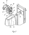
- the figures show that the valve closing device 14 is outside of the rotating circle determined by the free ends of the filling tubes 12. Contrary to the representations according to Figures 2 and 3, the valve 13a and After removal from the filling tube 12, the valve base is not yet in a flat position Condition, but the valve is still in a tube-like condition.
- the Valve closing device 14 is therefore on the respective filling tube 12 facing End face with a guide element and a shaped element.
- the guide element consists of a pivotable, plate-shaped pressing element 16, which by means of a Piston-cylinder unit 17 around a horizontal one facing away from the inlet side Axis 18 is pivotable.
- a Piston-cylinder unit 17 around a horizontal one facing away from the inlet side Axis 18 is pivotable.
- the axis 18 is transverse to the direction of the Valve bags 13.
- Below the pressure element 16 is a stretching and smoothing element 19 stored, which is a in the direction of flow of the valve bags horizontal axis of a motor 28 can be driven in rotation.
- the stretch and The smoothing element 19 and the pressing element 16 form an interaction Guide for the valve 13 of the valve bag 13.
- the stretching and smoothing element 19 is formed as a cage, as the figures show. Contrary to the illustration, it can also be designed as a brush. Contrary to the direction of flow of the valve bags 13 it is conical, so that the inlet gap is further reinforced. In not In more detail, at least the pressure element 16 is over light barriers or the piston-cylinder unit 17 controlled. As soon as the locking area of the valve completely below the plate-shaped pressing element 16 stands, the piston rod of the piston-cylinder unit 17 extends.
- the stretch and Smoothing element 19 is viewed from the filling tube with a view of the valve closing device 14 12 driven clockwise so that the bottom of the valve and if necessary the floor is pulled up. In the direction of the Seen valve bags 13 is directly behind the pressure element 16, the ultrasonic welding device 20 mounted.
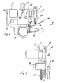
- the anvil is designed as an anvil wheel 21, and this is via a servo motor 27 and a drive train, not shown driven according to the direction of passage of the valve bags 13.
- the sonotrode 22 is arranged above, which in the embodiment according to FIG. 2 is certain.
- the entire ultrasonic welding device 20 is around a bolt 23 pivotable. This allows the distance between the anvil wheel 21 and the sonotrode 22 can be set, whereby a minimum distance must be observed so that no increased wear occurs.
- the precise adjustment is made by a rotatable one Set screw 24.
- the entire valve closing device 14 hangs on one Console 26 which is guided in at least one vertical column. Not by one drive, the entire valve closing device 14 in vertical direction. This is not just for adjustment purposes the filling tubes 12 of the rotor 11, but also to release the orbit of a not yet completely filled, hanging on a filling tube 12 sack during another revolution.
- the embodiment according to FIG. 3 differs from the embodiment according to Fig. 2 in that the sonotrode is designed as a sonotrode wheel 22, which can be driven by a drive motor 29.
- the drive for the anvil wheel 21 can be omitted in this case.
- the valve closing device 14 according to FIG. 4 corresponds to the embodiment according to FIG. 2. It is clearly shown here that there is an insertion gap on the inlet side is formed by the pressing element 16 and the stretching element 19.
- the Swiveling of the ultrasonic welding device 20 by the piston-cylinder unit 25 has the advantage that a compensatory movement can take place because the valves or the valve bottoms in the closing area fluctuate in thickness can.
- FIG. 5 shows the closing device according to FIGS. 2 and 4 in a top view. It can be clearly seen that the entire closing device is on one Console 26 is suspended.
- the invention is not restricted to the exemplary embodiments shown. Essential is that regardless of the number of filling tubes 12 of the rotor 11, the filled Valve bags pass through a valve closing device 14, which is continuous works so that the valve closing devices assigned to the filling tubes 12 can be omitted.
Landscapes
- Engineering & Computer Science (AREA)
- Mechanical Engineering (AREA)
- Physics & Mathematics (AREA)
- Fluid Mechanics (AREA)
- Basic Packing Technique (AREA)
- Package Closures (AREA)
- Valve Housings (AREA)
Abstract
Description
Dies gilt insbesondere dann, wenn die Verschließeinrichtungen nach dem Ultraschallschweißverfahren arbeiten.
Der Erfindung liegt die Aufgabe zugrunde, eine Anlage der eingangs näher beschriebenen Art so zu gestalten, dass ohne negative Beeinträchtigung des Ventilverschlusses in konstruktiv einfacher Weise der technische Aufwand und somit auch die Kosten vermindert werden.
- Fig. 1
- eine erfindungsgemäße Anlag als Schemaskizze in einer Draufsicht;
- Fig. 2
- das Füllrohr einer rotierenden Füllmaschine sowie den abgenommenen Ventilsack und die Verschließeinrichtung in einer ersten Ausführung mit einer feststehenden Sonotrode;
- Fig. 3
- das Füllrohr einer rotierenden Füllmaschine, den abgenommenen Ventilsack und die Verschließeinrichtung in einer zweiten Ausführung mit einer rotierend antreibbaren Sonotrode;
- Fig. 4
- die Verschließeinrichtung in einer Seitenansicht mit Blick auf die einzelnen Aggregate;
- Fig. 5
- eine der Fig. 4 entsprechende Stimansicht in Richtung des Pfeiles 5 in der Fig. 4 gesehen;
Claims (13)
- Anlage (10) zum Füllen von Ventilsäcken (13) und anschließendem Verschließen der Ventile (13a), die mit einer rotierenden Füllmaschine ausgestattet ist, die einen Rotor (11) enthält, der mit mehreren Füllrohren (12) bestückt ist, auf die die Ventile (13a) der zu füllenden Ventilsäcke (13) aufsteckbar sind, wobei die Anlage (10) derart ausgelegt ist, dass die Ventile (13a) im Ultraschallschweißverfahren verschließbar sind, gekennzeichnet durch eine einzige außerhalb des äußeren Drehkreises des ventilsackfreien Rotors (12) stationär, jedoch verstellbar aufgestellte Ventilverschließeinrichtung (14), die mit Führungs- und/oder Formelementen (16, 19) für die Verschließbereiche der Ventile (13a) der kontinuierlich durchlaufenden Ventilsäcke (13) versehen ist, und bei der den Führungs- und/oder Formelementen (16) der Amboss (21) und die Sonotrode (22) einer Ultraschallschweißeinrichtung (20) nachgeschaltet sind.
- Anlage nach Anspruch 1, dadurch gekennzeichnet, dass die Ventilverschließeinrichtung (14) zumindest teilweise in der Umlaufbahn der auf die Füllrohre (12) des Rotors (11) aufgesteckten Ventilsäcke (13) liegt.
- Anlage nach Anspruch 1, dadurch gekennzeichnet, dass der von dem Amboss (21) und der Sonotrode (22) der Ultraschallschweißeinrichtung (20) gebildete Durchlaufspalt höhenmäßig im Bereich der Mittellängsachsen der Füllrohre (12) liegt.
- Anlage nach Anspruch 1 oder 3, dadurch gekennzeichnet, dass die Ventilverschließeinrichtung (14) längs einer vertikalen, ortsfesten Führungsbahn verfahrbar ist.
- Anlage nach Anspruch 4, dadurch gekennzeichnet, dass die Ventilverschließeinrichtung zur Höhenverstellung mit einem Stellantrieb versehen ist.
- Anlage nach Anspruch 1, dadurch gekennzeichnet, dass die Führungselemente aus einer von oben auf den Verschließbereich des Ventils (13a) aufsetzbaren Andrückelement (16) gebildet ist, welches um eine horizontale sowie quer zur Durchlaufrichtung der Ventilsäcke (13) stehenden Achse (18) schwenkbar ist, und dass die Formelemente aus einem Streck- und Glättelement (19) bestehen, welches um eine in der Durchlaufrichtung des Ventilsäcke (13) verlaufende Achse rotierend antreibbar ist, so dass das Ventil von unten, von dem dem Ventilboden gegenüberliegenden Boden des Ventilsackes (13) aus in einen flachen Zustand verformbar ist.
- Anlage nach Anspruch 6, dadurch gekennzeichnet, dass das Andrückelement (16) als Andrückplatte oder Andrückschuh ausgebildet und mittels einer Kolbenzylindereinheit (17) schwenkbar ist.
- Anlage nach Anspruch 6, dadurch gekennzeichnet, dass das Streck- und Glättelement (19) unterhalb des Andrückelementes (16) angeordnet ist und aus einem rotierend antreibbaren Käfig oder einer Bürste besteht, der bzw. die zur Einlaufseite der Ventilsäcke hin sich im Querschnitt verkleinert.
- Anlage nach einem oder mehreren der vorhergehenden Ansprüche 1 bis 8, dadurch gekennzeichnet, dass die der Ventilverschließeinrichtung (14) zugeführten Säcke mit dem Rotor (11) der Anlage (10) in einer Mitnahmeverbindung stehen.
- Anlage nach Anspruch 1, dadurch gekennzeichnet, dass der Amboss der Ultraschallschweißeinrichtung (20) als rotierend antreibbares Ambossrad (21) ausgebildet und auf einer ortsfesten, rotierend antreibbaren Welle drehfest aufgesetzt ist.
- Anlage nach einem oder mehreren der vorhergehenden Ansprüche 1 bis 10, dadurch gekennzeichnet, dass die die Sonotrode (22) enthaltende Ultraschallschweißeinheit an einem Schwenkhebel angeordnet ist, und dass der Abstand zwischen dem Ambossrad und der Sonotrode mittels eines einstellbaren Anschlages (24) einstellbar ist, wobei eine definierte ren Anschlages (24) einstellbar ist, wobei eine definierte Andrückkraft durch eine Kolben-Zylinder-Einheit (25) erzeugbar ist.
- Anlage nach Anspruch 1, dadurch gekennzeichnet, dass zumindest die Sonotrode der Ultraschallschweißvorrichtung (20) als rotierend antreibbares Sonotrodenrad (22) ausgebildet ist, und dass der Amboss (21) die Sonotrode (22) die Führungs- und die Formelemente (16, 19) an der dem Rotor (11) der Anlage (10) abgewandten Seite angeordnet sind.
- Anlage nach einem oder mehreren der vorhergehenden Ansprüche 1 bis 12, dadurch gekennzeichnet, dass die Ventilverschließeinrichtung (14) als Baueinheit an einer Konsole (26) angeordnet und mittels eines Stellantriebes höhenverstellbar ist.
Applications Claiming Priority (2)
| Application Number | Priority Date | Filing Date | Title |
|---|---|---|---|
| DE20305725U DE20305725U1 (de) | 2003-04-09 | 2003-04-09 | Rotierende Füllmaschine mit Verschließvorrichtung |
| DE20305725U | 2003-04-09 |
Publications (2)
| Publication Number | Publication Date |
|---|---|
| EP1466829A1 true EP1466829A1 (de) | 2004-10-13 |
| EP1466829B1 EP1466829B1 (de) | 2011-05-04 |
Family
ID=27588840
Family Applications (1)
| Application Number | Title | Priority Date | Filing Date |
|---|---|---|---|
| EP04007033A Expired - Lifetime EP1466829B1 (de) | 2003-04-09 | 2004-03-24 | Rotierende Füllmaschine mit Verschliessvorrichtung |
Country Status (5)
| Country | Link |
|---|---|
| EP (1) | EP1466829B1 (de) |
| AT (1) | ATE508052T1 (de) |
| DE (2) | DE20305725U1 (de) |
| DK (1) | DK1466829T3 (de) |
| ES (1) | ES2366087T3 (de) |
Cited By (7)
| Publication number | Priority date | Publication date | Assignee | Title |
|---|---|---|---|---|
| DE102005062137A1 (de) * | 2005-12-22 | 2007-07-05 | Haver & Boecker Ohg | Verfahren und Vorrichtung zum Verschweißen von Werkstücken |
| EP1808375A1 (de) * | 2006-01-13 | 2007-07-18 | Hilcona Aktiengesellschaft | Vorrichtung zur Dichtversiegelung von Verbundfolienbeuteln |
| WO2009000288A1 (de) | 2007-06-25 | 2008-12-31 | Haver & Boecker Ohg | Verfahren und vorrichtung zum verschweissen von säcken |
| DE102007030382A1 (de) * | 2007-06-29 | 2009-01-08 | Haver & Boecker Ohg | Verfahren und Vorrichtung zum Verschweißen von Säcken |
| WO2016063238A1 (en) * | 2014-10-22 | 2016-04-28 | Italcementi S.P.A. | Airtight sealing station and method for bags of loose and/or powdered materials as well as a system and process for bagging loose and/or powdered materials using them |
| US10913211B2 (en) | 2017-05-30 | 2021-02-09 | Campbell Soup Company | High rate ultrasonic sealer |
| CN112693646A (zh) * | 2019-10-22 | 2021-04-23 | Fl史密斯公司 | 用于袋射击施加器组件的袋射击系统 |
Families Citing this family (4)
| Publication number | Priority date | Publication date | Assignee | Title |
|---|---|---|---|---|
| DE102005059004A1 (de) | 2005-12-08 | 2007-06-14 | Haver & Boecker Ohg | Verfahren und Vorrichtung zum Füllen von Säcken |
| DE102006024870A1 (de) * | 2006-05-24 | 2007-11-29 | Haver & Boecker Ohg | Verfahren und Anlage zum Befüllen von Behältnissen, insbesondere zum Füllen von Säcken |
| DE102007013213B4 (de) | 2007-03-15 | 2022-12-08 | Haver & Boecker Ohg | Packmaschine und Verfahren zum Füllen von Säcken |
| CN113277175B (zh) * | 2021-06-11 | 2024-11-08 | 山东一唯自动化有限公司 | 一种阀口袋超声波焊接机构 |
Citations (4)
| Publication number | Priority date | Publication date | Assignee | Title |
|---|---|---|---|---|
| EP1010619A1 (de) * | 1998-12-14 | 2000-06-21 | Firma Haver & Boecker | Füllmaschine zum Füllen von Ventilsäcken |
| EP1164079A1 (de) * | 2000-05-12 | 2001-12-19 | Firma Haver & Boecker | Rotierende Füllmaschine |
| CH692288A5 (de) * | 1996-12-16 | 2002-04-30 | Haver & Boecker | Füllmaschine. |
| DE20206429U1 (de) | 2002-04-23 | 2002-06-27 | Haver & Boecker, 59302 Oelde | Füllmaschine zum Füllen von Ventilsäcken |
Family Cites Families (3)
| Publication number | Priority date | Publication date | Assignee | Title |
|---|---|---|---|---|
| DE819973C (de) | 1947-03-20 | 1951-11-12 | St Regis Paper Co | Vorrichtung zum Verschliessen der Ventile an Ventilsaecken |
| DE3104968A1 (de) | 1979-08-13 | 1982-08-19 | Natronag Papierproduktion Gmbh & Co, Papiersackfabriken Kg, 3380 Goslar | "verfahren und vorrichtung zum verschliessen eines ventilsackes" |
| DE29912490U1 (de) | 1999-07-23 | 2001-02-15 | HERMA GmbH + Co KG, 70327 Stuttgart | Rotative Ultraschall-Schweißvorrichtung |
-
2003
- 2003-04-09 DE DE20305725U patent/DE20305725U1/de not_active Expired - Lifetime
-
2004
- 2004-03-24 DK DK04007033.6T patent/DK1466829T3/da active
- 2004-03-24 DE DE502004012463T patent/DE502004012463D1/de not_active Expired - Lifetime
- 2004-03-24 EP EP04007033A patent/EP1466829B1/de not_active Expired - Lifetime
- 2004-03-24 ES ES04007033T patent/ES2366087T3/es not_active Expired - Lifetime
- 2004-03-24 AT AT04007033T patent/ATE508052T1/de active
Patent Citations (4)
| Publication number | Priority date | Publication date | Assignee | Title |
|---|---|---|---|---|
| CH692288A5 (de) * | 1996-12-16 | 2002-04-30 | Haver & Boecker | Füllmaschine. |
| EP1010619A1 (de) * | 1998-12-14 | 2000-06-21 | Firma Haver & Boecker | Füllmaschine zum Füllen von Ventilsäcken |
| EP1164079A1 (de) * | 2000-05-12 | 2001-12-19 | Firma Haver & Boecker | Rotierende Füllmaschine |
| DE20206429U1 (de) | 2002-04-23 | 2002-06-27 | Haver & Boecker, 59302 Oelde | Füllmaschine zum Füllen von Ventilsäcken |
Cited By (10)
| Publication number | Priority date | Publication date | Assignee | Title |
|---|---|---|---|---|
| DE102005062137A1 (de) * | 2005-12-22 | 2007-07-05 | Haver & Boecker Ohg | Verfahren und Vorrichtung zum Verschweißen von Werkstücken |
| EP1800837A3 (de) * | 2005-12-22 | 2008-04-02 | Haver & Boecker oHG | Verfahren und Vorrichtung zum Verschweissen von Werkstücken |
| EP1808375A1 (de) * | 2006-01-13 | 2007-07-18 | Hilcona Aktiengesellschaft | Vorrichtung zur Dichtversiegelung von Verbundfolienbeuteln |
| WO2009000288A1 (de) | 2007-06-25 | 2008-12-31 | Haver & Boecker Ohg | Verfahren und vorrichtung zum verschweissen von säcken |
| EA021304B1 (ru) * | 2007-06-25 | 2015-05-29 | Хавер Энд Боекер Охг | Устройство для сварки пакетов |
| DE102007030382A1 (de) * | 2007-06-29 | 2009-01-08 | Haver & Boecker Ohg | Verfahren und Vorrichtung zum Verschweißen von Säcken |
| WO2016063238A1 (en) * | 2014-10-22 | 2016-04-28 | Italcementi S.P.A. | Airtight sealing station and method for bags of loose and/or powdered materials as well as a system and process for bagging loose and/or powdered materials using them |
| US10913211B2 (en) | 2017-05-30 | 2021-02-09 | Campbell Soup Company | High rate ultrasonic sealer |
| US11312085B2 (en) | 2017-05-30 | 2022-04-26 | Campbell Soup Company | High rate ultrasonic sealer |
| CN112693646A (zh) * | 2019-10-22 | 2021-04-23 | Fl史密斯公司 | 用于袋射击施加器组件的袋射击系统 |
Also Published As
| Publication number | Publication date |
|---|---|
| DK1466829T3 (da) | 2011-08-22 |
| ES2366087T3 (es) | 2011-10-17 |
| DE502004012463D1 (de) | 2011-06-16 |
| ATE508052T1 (de) | 2011-05-15 |
| DE20305725U1 (de) | 2003-07-10 |
| EP1466829B1 (de) | 2011-05-04 |
Similar Documents
| Publication | Publication Date | Title |
|---|---|---|
| DE3219267C2 (de) | ||
| DE68903016T2 (de) | Vorrichtung zum Verschliessen von Behältern mittels einer versiegelbaren Folie. | |
| EP2999635A1 (de) | Behälterbehandlungsmaschine sowie verfahren zum betrieb einer behälterbehandlungsmaschine | |
| EP1466829A1 (de) | Anlage zum Füllen von Ventilsäcken | |
| DE2339518C2 (de) | Vorrichtung zum Herstellen rohrförmiger Behälter-Grundkörper aus einem Zuschnitt | |
| WO2007090652A1 (de) | Hubvorrichtung für eine verpackungsmaschine | |
| DE2407358A1 (de) | Behaelter-verschliessvorrichtung | |
| EP1010619B1 (de) | Füllmaschine zum Füllen von Ventilsäcken | |
| DE3702954A1 (de) | Gruppiereinrichtung zur bildung von behaeltergruppen | |
| EP3269539B1 (de) | Vorrichtung zum öffnen eines endbereichs eines schlauchförmigen sackkörpers | |
| DE1586093A1 (de) | Einrichtung zum Aufbringen von Aufreissstreifen auf ein Einschlagmaterialband | |
| DE2337939B2 (de) | Verfahren zum Umformen eines kontinuierlich bewegten Schlauches und Vorrichtung zur Durchfuhrung des Verfahrens | |
| DE3637701A1 (de) | Saugfoerderanlage | |
| DE2122990A1 (de) | Vorrichtung zur Bearbeitung der Kanten von Glasscheiben oder dergleichen | |
| DE4406089C2 (de) | Vorrichtung zum Abfüllen von Tabletten oder dergleichen in Tablettenröhrchen | |
| DE10122752B4 (de) | Antrieb für höhenverstellbare Behälterträger an Abfüllmaschinen | |
| DE19750075A1 (de) | Verfahren und Vorrichtung zum Herstellen und Aufbringen von Deckeln aus einer Werkstoffbahn, insbesondere Deckblattfolien aus einer dünnen Kunststoffolienbahn | |
| DE20012051U1 (de) | Vorrichtung zum Aufrichten und Verkleben von Faltschachtelzuschnitten | |
| EP0492140A2 (de) | Tiefziehmaschine zum Formen, Füllen und Verschliessen von Behältern aus einer mittels einer Fördereinrichtung taktweise transportierten thermoplastischen Kunststoffolienbahn | |
| DE4441278A1 (de) | Schnittanordnung zum Schneiden von Teebeuteln aus Bahnmaterialien | |
| EP0703060A1 (de) | Verfahren zum Austransportieren und Ablegen bzw. Stapeln von tiefgezogenen Formteilen und Vorrichtung zur Durchführung des Verfahrens | |
| EP3449079B1 (de) | Verfahren und vorrichtung zum versiegeln von isolierglas-rohlingen | |
| DE2950553A1 (de) | Maschine zum herstellen und fuellen von saecken | |
| DE2401448C3 (de) | Vorrichtung zum Verpacken von abfüllbaren Produkten | |
| DE1561468C (de) | Vorrichtung zum Aufziehen der Enden von Schlauchabschnitten aus Kunststoffolie |
Legal Events
| Date | Code | Title | Description |
|---|---|---|---|
| PUAI | Public reference made under article 153(3) epc to a published international application that has entered the european phase |
Free format text: ORIGINAL CODE: 0009012 |
|
| AK | Designated contracting states |
Kind code of ref document: A1 Designated state(s): AT BE BG CH CY CZ DE DK EE ES FI FR GB GR HU IE IT LI LU MC NL PL PT RO SE SI SK TR |
|
| AX | Request for extension of the european patent |
Extension state: AL LT LV MK |
|
| 17P | Request for examination filed |
Effective date: 20050129 |
|
| AKX | Designation fees paid |
Designated state(s): AT BE BG CH CY CZ DE DK EE ES FI FR GB GR HU IE IT LI LU MC NL PL PT RO SE SI SK TR |
|
| 17Q | First examination report despatched |
Effective date: 20081203 |
|
| RTI1 | Title (correction) |
Free format text: ROTARY FILLING MACHINE WITH CLOSURE DEVICE |
|
| GRAP | Despatch of communication of intention to grant a patent |
Free format text: ORIGINAL CODE: EPIDOSNIGR1 |
|
| GRAS | Grant fee paid |
Free format text: ORIGINAL CODE: EPIDOSNIGR3 |
|
| GRAA | (expected) grant |
Free format text: ORIGINAL CODE: 0009210 |
|
| AK | Designated contracting states |
Kind code of ref document: B1 Designated state(s): AT BE BG CH CY CZ DE DK EE ES FI FR GB GR HU IE IT LI LU MC NL PL PT RO SE SI SK TR |
|
| REG | Reference to a national code |
Ref country code: GB Ref legal event code: FG4D Free format text: NOT ENGLISH |
|
| REG | Reference to a national code |
Ref country code: CH Ref legal event code: EP |
|
| REG | Reference to a national code |
Ref country code: IE Ref legal event code: FG4D Free format text: LANGUAGE OF EP DOCUMENT: GERMAN |
|
| REF | Corresponds to: |
Ref document number: 502004012463 Country of ref document: DE Date of ref document: 20110616 Kind code of ref document: P |
|
| REG | Reference to a national code |
Ref country code: DE Ref legal event code: R096 Ref document number: 502004012463 Country of ref document: DE Effective date: 20110616 |
|
| REG | Reference to a national code |
Ref country code: NL Ref legal event code: T3 |
|
| REG | Reference to a national code |
Ref country code: DK Ref legal event code: T3 |
|
| REG | Reference to a national code |
Ref country code: ES Ref legal event code: FG2A Ref document number: 2366087 Country of ref document: ES Kind code of ref document: T3 Effective date: 20111017 |
|
| PG25 | Lapsed in a contracting state [announced via postgrant information from national office to epo] |
Ref country code: PT Free format text: LAPSE BECAUSE OF FAILURE TO SUBMIT A TRANSLATION OF THE DESCRIPTION OR TO PAY THE FEE WITHIN THE PRESCRIBED TIME-LIMIT Effective date: 20110905 Ref country code: SE Free format text: LAPSE BECAUSE OF FAILURE TO SUBMIT A TRANSLATION OF THE DESCRIPTION OR TO PAY THE FEE WITHIN THE PRESCRIBED TIME-LIMIT Effective date: 20110504 |
|
| PG25 | Lapsed in a contracting state [announced via postgrant information from national office to epo] |
Ref country code: GR Free format text: LAPSE BECAUSE OF FAILURE TO SUBMIT A TRANSLATION OF THE DESCRIPTION OR TO PAY THE FEE WITHIN THE PRESCRIBED TIME-LIMIT Effective date: 20110805 Ref country code: CY Free format text: LAPSE BECAUSE OF FAILURE TO SUBMIT A TRANSLATION OF THE DESCRIPTION OR TO PAY THE FEE WITHIN THE PRESCRIBED TIME-LIMIT Effective date: 20110504 Ref country code: FI Free format text: LAPSE BECAUSE OF FAILURE TO SUBMIT A TRANSLATION OF THE DESCRIPTION OR TO PAY THE FEE WITHIN THE PRESCRIBED TIME-LIMIT Effective date: 20110504 Ref country code: SI Free format text: LAPSE BECAUSE OF FAILURE TO SUBMIT A TRANSLATION OF THE DESCRIPTION OR TO PAY THE FEE WITHIN THE PRESCRIBED TIME-LIMIT Effective date: 20110504 |
|
| REG | Reference to a national code |
Ref country code: IE Ref legal event code: FD4D |
|
| PG25 | Lapsed in a contracting state [announced via postgrant information from national office to epo] |
Ref country code: IE Free format text: LAPSE BECAUSE OF FAILURE TO SUBMIT A TRANSLATION OF THE DESCRIPTION OR TO PAY THE FEE WITHIN THE PRESCRIBED TIME-LIMIT Effective date: 20110504 Ref country code: CZ Free format text: LAPSE BECAUSE OF FAILURE TO SUBMIT A TRANSLATION OF THE DESCRIPTION OR TO PAY THE FEE WITHIN THE PRESCRIBED TIME-LIMIT Effective date: 20110504 Ref country code: EE Free format text: LAPSE BECAUSE OF FAILURE TO SUBMIT A TRANSLATION OF THE DESCRIPTION OR TO PAY THE FEE WITHIN THE PRESCRIBED TIME-LIMIT Effective date: 20110504 |
|
| PG25 | Lapsed in a contracting state [announced via postgrant information from national office to epo] |
Ref country code: SK Free format text: LAPSE BECAUSE OF FAILURE TO SUBMIT A TRANSLATION OF THE DESCRIPTION OR TO PAY THE FEE WITHIN THE PRESCRIBED TIME-LIMIT Effective date: 20110504 Ref country code: RO Free format text: LAPSE BECAUSE OF FAILURE TO SUBMIT A TRANSLATION OF THE DESCRIPTION OR TO PAY THE FEE WITHIN THE PRESCRIBED TIME-LIMIT Effective date: 20110504 Ref country code: PL Free format text: LAPSE BECAUSE OF FAILURE TO SUBMIT A TRANSLATION OF THE DESCRIPTION OR TO PAY THE FEE WITHIN THE PRESCRIBED TIME-LIMIT Effective date: 20110504 |
|
| PLBE | No opposition filed within time limit |
Free format text: ORIGINAL CODE: 0009261 |
|
| STAA | Information on the status of an ep patent application or granted ep patent |
Free format text: STATUS: NO OPPOSITION FILED WITHIN TIME LIMIT |
|
| 26N | No opposition filed |
Effective date: 20120207 |
|
| REG | Reference to a national code |
Ref country code: DE Ref legal event code: R097 Ref document number: 502004012463 Country of ref document: DE Effective date: 20120207 |
|
| PGFP | Annual fee paid to national office [announced via postgrant information from national office to epo] |
Ref country code: DK Payment date: 20120326 Year of fee payment: 9 |
|
| PG25 | Lapsed in a contracting state [announced via postgrant information from national office to epo] |
Ref country code: MC Free format text: LAPSE BECAUSE OF NON-PAYMENT OF DUE FEES Effective date: 20120331 |
|
| REG | Reference to a national code |
Ref country code: CH Ref legal event code: PL |
|
| PG25 | Lapsed in a contracting state [announced via postgrant information from national office to epo] |
Ref country code: CH Free format text: LAPSE BECAUSE OF NON-PAYMENT OF DUE FEES Effective date: 20120331 Ref country code: LI Free format text: LAPSE BECAUSE OF NON-PAYMENT OF DUE FEES Effective date: 20120331 |
|
| REG | Reference to a national code |
Ref country code: AT Ref legal event code: MM01 Ref document number: 508052 Country of ref document: AT Kind code of ref document: T Effective date: 20120324 |
|
| PG25 | Lapsed in a contracting state [announced via postgrant information from national office to epo] |
Ref country code: BG Free format text: LAPSE BECAUSE OF FAILURE TO SUBMIT A TRANSLATION OF THE DESCRIPTION OR TO PAY THE FEE WITHIN THE PRESCRIBED TIME-LIMIT Effective date: 20110804 |
|
| PG25 | Lapsed in a contracting state [announced via postgrant information from national office to epo] |
Ref country code: AT Free format text: LAPSE BECAUSE OF NON-PAYMENT OF DUE FEES Effective date: 20120324 |
|
| REG | Reference to a national code |
Ref country code: DK Ref legal event code: EBP Ref country code: DK Ref legal event code: EBP Effective date: 20130331 |
|
| PG25 | Lapsed in a contracting state [announced via postgrant information from national office to epo] |
Ref country code: DK Free format text: LAPSE BECAUSE OF NON-PAYMENT OF DUE FEES Effective date: 20130331 |
|
| PGFP | Annual fee paid to national office [announced via postgrant information from national office to epo] |
Ref country code: NL Payment date: 20140320 Year of fee payment: 11 |
|
| PG25 | Lapsed in a contracting state [announced via postgrant information from national office to epo] |
Ref country code: LU Free format text: LAPSE BECAUSE OF NON-PAYMENT OF DUE FEES Effective date: 20120324 |
|
| PGFP | Annual fee paid to national office [announced via postgrant information from national office to epo] |
Ref country code: IT Payment date: 20140328 Year of fee payment: 11 Ref country code: TR Payment date: 20140318 Year of fee payment: 11 Ref country code: ES Payment date: 20140324 Year of fee payment: 11 Ref country code: FR Payment date: 20140319 Year of fee payment: 11 |
|
| PGFP | Annual fee paid to national office [announced via postgrant information from national office to epo] |
Ref country code: GB Payment date: 20140324 Year of fee payment: 11 |
|
| PG25 | Lapsed in a contracting state [announced via postgrant information from national office to epo] |
Ref country code: HU Free format text: LAPSE BECAUSE OF FAILURE TO SUBMIT A TRANSLATION OF THE DESCRIPTION OR TO PAY THE FEE WITHIN THE PRESCRIBED TIME-LIMIT Effective date: 20040324 |
|
| PGFP | Annual fee paid to national office [announced via postgrant information from national office to epo] |
Ref country code: BE Payment date: 20140320 Year of fee payment: 11 |
|
| PGFP | Annual fee paid to national office [announced via postgrant information from national office to epo] |
Ref country code: DE Payment date: 20140401 Year of fee payment: 11 |
|
| REG | Reference to a national code |
Ref country code: DE Ref legal event code: R119 Ref document number: 502004012463 Country of ref document: DE |
|
| GBPC | Gb: european patent ceased through non-payment of renewal fee |
Effective date: 20150324 |
|
| REG | Reference to a national code |
Ref country code: NL Ref legal event code: MM Effective date: 20150401 |
|
| PG25 | Lapsed in a contracting state [announced via postgrant information from national office to epo] |
Ref country code: IT Free format text: LAPSE BECAUSE OF NON-PAYMENT OF DUE FEES Effective date: 20150324 |
|
| REG | Reference to a national code |
Ref country code: FR Ref legal event code: ST Effective date: 20151130 |
|
| PG25 | Lapsed in a contracting state [announced via postgrant information from national office to epo] |
Ref country code: DE Free format text: LAPSE BECAUSE OF NON-PAYMENT OF DUE FEES Effective date: 20151001 Ref country code: GB Free format text: LAPSE BECAUSE OF NON-PAYMENT OF DUE FEES Effective date: 20150324 |
|
| PG25 | Lapsed in a contracting state [announced via postgrant information from national office to epo] |
Ref country code: FR Free format text: LAPSE BECAUSE OF NON-PAYMENT OF DUE FEES Effective date: 20150331 |
|
| REG | Reference to a national code |
Ref country code: ES Ref legal event code: FD2A Effective date: 20160930 |
|
| PG25 | Lapsed in a contracting state [announced via postgrant information from national office to epo] |
Ref country code: ES Free format text: LAPSE BECAUSE OF NON-PAYMENT OF DUE FEES Effective date: 20150325 |
|
| PG25 | Lapsed in a contracting state [announced via postgrant information from national office to epo] |
Ref country code: NL Free format text: LAPSE BECAUSE OF NON-PAYMENT OF DUE FEES Effective date: 20150401 |
|
| PG25 | Lapsed in a contracting state [announced via postgrant information from national office to epo] |
Ref country code: BE Free format text: LAPSE BECAUSE OF NON-PAYMENT OF DUE FEES Effective date: 20150331 |
|
| PG25 | Lapsed in a contracting state [announced via postgrant information from national office to epo] |
Ref country code: TR Free format text: LAPSE BECAUSE OF NON-PAYMENT OF DUE FEES Effective date: 20150324 |