Technical Field
The present invention relates to a method for vapor
phase catalytic oxidation involving using a fixed bed
multi-tube heat-exchanger type reactor provided with a
plurality of reaction tubes and feeding a raw material
gas for reaction. The present invention more
specifically relates to a method for vapor phase
catalytic oxidation which is almost free of variations
in reaction states in respective reaction tubes of the
fixed bed multi-tube heat-exchanger type reactor.
In addition, the present invention relates to a
method for packing a catalyst in the reaction tubes used
in the method for vapor phase catalytic oxidation.
Background Art
A fixed bed multi-tube heat-exchanger type reactor
provided with a plurality of reaction tubes (hereinafter,
may be referred to as "fixed bed multi-tube reactor")
has been known up to now. Further, a method of vapor
phase catalytic oxidation using the fixed bed multi-tube
heat-exchanger type reactor has been known.
A method of packing a catalyst in the fixed bed
multi-tube heat-exchanger type reactor generally
involves packing by charging the catalyst from an upper
portion of the reactor and allowing the catalyst to fall.
However, according to this method, packed states differ
for the respective reaction tubes because of reasons
including: (1) the catalyst is powdered or degraded by
physical impact of the catalyst charged to fall; and (2)
packing time varies. To be specific, a level of
powdering or degradation of the catalyst during catalyst
packing differs for the respective reaction tubes.
Further, long packing time results in a large packing
density, and short packing time results in a small
packing density. Therefore, according to a conventional
packing method, the catalyst was hardly packed to
provide uniform pressure states of the respective
reaction tubes, particularly a pressure loss, which
becomes an important factor in an oxidation reaction.
No technique exists aiming to provide a uniform
pressure loss for the respective reaction tubes of the
fixed bed multi-tube reactor, and methods for solving
the problem (1) or (2) are proposed.
Examples of a method of suppressing powdering or
degradation of the catalyst during catalyst packing
include the following.
JP 2852712 B discloses a method of improving
mechanical strength of a catalyst by coating the
catalyst with an organic polymer compound having
depolymerizing property on a surface of the catalyst.
However, a uniform coating of all of the catalyst is
difficult, and catalyst strength varies even if the
catalyst strength increases as a whole. The coating has
some effects in reducing the pressure loss, but this
method is far from a satisfying method of providing a
uniform pressure loss for the respective reaction tubes.
Further, JP 05-031351 A discloses a method of
interposing a cord-like substance, having a shape and a
thickness substantially not obstructing falling of a
catalyst, inside a reactor when packing the catalyst
from an upper portion of the reactor by allowing to fall.
A slight effect is provided for preventing powdering or
degradation of the catalyst, but an effect of catalyst
packing time on packing density is unavoidable. Thus,
this method is far from a satisfying method for
providing a uniform pressure loss in the respective
reaction tubes.
Further, JP 10-277381 A discloses a method
involving packing dry ice prior to packing a catalyst by
allowing to fall, packing the catalyst, and subsequently
vaporizing and removing the dry ice.
Further, JP 09-141084 A discloses a method of
packing a catalyst from an upper portion of a reactor
involves packing a liquid substance inside the reactor,
subsequently packing the catalyst, and then removing the
liquid substance. However, these methods of packing the
dry ice or the liquid substance in advance are far from
satisfying methods industrially because post-treatment
after catalyst packing involves time and effort, and
handled substances may deteriorate a working environment.
On the other hand, examples of methods of
controlling packing operation (time) include the
following.
JP 11-333282 A discloses a method using an
automatic packing machine provided with a catalyst feed
conveyor and capable of controlling catalyst packing
time. The patent discloses that the packing machine
provides uniform packing time, allowing a uniform
pressure loss in the respective reaction tubes. However,
a difference in pressure loss may result depending on
the catalyst, and thus, the method is far from
satisfying.
Next, a fixed bed multi-tube heat-exchanger type
reactor, using a heating medium for absorbing heat of
reaction generated inside reaction tubes is
conventionally provided with a plate for changing
passage of the heating medium, called a baffle, to allow
uniform flow of the heating medium inside the reactor as
much as possible.
Such a fixed bed multi-tube heat-exchanger type
reactor provided with a baffle did not have particular
problems when a size of a plant was small. However,
following problems arise when a size of the plant, that
is, a reactor becomes large for increasing productivity
as of today.
In other words, a non-uniform portion of a flow of
the heating medium forms inside a reactor shell. A
state of poor heat removal forms in part of reaction
tubes among a plurality of reaction tubes inside the
reactor. A localized abnormal high-temperature zone
(hot spot) may form in the reaction tubes which are in a
state of poor heat removal, possibly resulting in a
reaction out of control.
Further, such different reaction states among the
reaction tubes result in a problem of not preventing
formation of reaction tubes in which a reaction becomes
out of control. In addition, the different states
result in problems of decreasing an yield of a target
product gas and of decreasing a catalyst life.
On the other hand, an increase of raw material gas
feed for enhancing the productivity results in portions
where heat removal is slower than heat generation during
a reaction, even with a conventional reactor of a small
size. Thus, problems arise such as the above hot spots.
In other words, a conventional method for vapor
phase catalytic oxidation using the fixed bed multi-tube
heat-exchanger type reactor was not a method for vapor
phase catalytic oxidation exhibiting satisfactory
results such as effectively preventing forming of hot
spots, yielding a large amount of a reaction product gas,
and having a long catalyst life.
Further, the method of packing the catalyst in the
reaction tubes of the fixed bed multi-tube heat-exchanger
type reactor as described above generally
involves using a packing funnel. The catalyst is packed
by providing the reaction tubes with the packing funnel,
and packing the catalyst by charging the catalyst and
allowing the catalyst to fall through the packing funnel.
However, the powdered or degraded catalyst formed
during transfer, transport, and handling of the catalyst
is packed in the reaction tubes as well according to
this method. Variations of pressure loss becomes large,
which is a particularly important factor in an oxidation
reaction during a production step of acrylic acid or
methacrylic acid (hereinafter, may be referred to as
"(meth)acrylic acid"), and thus, this method is far from
a satisfying packing method for providing a uniform
reaction.
Up to now, no technique is available for separating
and removing the powdered or degraded catalyst in the
packed catalyst during catalyst packing. The method as
described above is merely proposed for suppressing
powdering or degradation of the catalyst during catalyst
packing.
However, those methods had problems in that
powdering or degradation of the catalyst caused by
vibration or impact taking place during transfer,
transport, and handling of the catalyst from.catalyst
production to catalyst packing or the like in the
reaction tubes of the fixed bed multi-tube reactor were
hardly evaded. In addition, the catalyst was packed in
the reaction tubes of the fixed bed multi-tube reactor
together with the powdered or degraded catalyst or the
like.
Further, when packing a catalyst in the reaction
tubes of the fixed bed multi-tube heat-exchanger type
reactor, the method as described above is employed to
pack the catalyst by allowing the catalyst to fall from
an upper portion of the reactor.
However, the catalyst may be powdered or degraded
from physical impact during falling of the catalyst
according to this method. For preventing the above, the
catalyst itself must have mechanical strength above some
level or the packing method must be somehow devised.
The mechanical strength of the catalyst can be
improved to a certain degree by adjusting a molding
pressure of the catalyst or devising operations of
molding or support. However, the catalyst having
enhanced mechanical strength through those techniques
resulted in reducing specific surface areas of the
catalyst, reducing active sites effective for a reaction,
and not allowing control of pore distribution effective
for reaction. Thus, problems arouse such that an yield
of the target product was reduced and the catalyst was
not practical.
Further, examples of the method of suppressing
powdering or degradation of the catalyst during catalyst
packing include the above methods disclosed in JP
2852712 B, JP 05-031351 A, JP 10-277381 A, and JP 09-141084.
However, a uniform coating of all of the catalyst
is difficult for the method of enhancing the mechanical
strength of the catalyst by coating the catalyst, and
catalyst strength varies even if the catalyst strength
increases as a whole. The coating has some effects in
reducing powdering or degradation of the catalyst, but
this method requires a step of coating during catalyst
production and is far from a satisfying method.
The method of interposing a cord-like substance
provides an effect of preventing powdering or
degradation of the catalyst. However, the method
requires an operation of pulling the cord-like substance
upward while packing the catalyst. Effects such as
extending the packing operation time or the like are
unavoidable, and thus, this method is far from
satisfying.
The method of packing the dry ice or the liquid
substance before catalyst packing may result in post
treatment taking time and effort after catalyst packing
and deterioration of the working environment depending
on the handled substances, and thus, is far from
satisfying industrially.
Disclosure of the Invention
A first invention of the present invention has been
made in view of the above problems, and an object of the
first invention is to provide a method for vapor phase
catalytic oxidation in which a vapor phase catalytic
oxidation reaction through packing a catalyst in
reaction tubes of a fixed bed multi-tube heat-exchanger
type reactor proceeds in the respective reaction tubes
having a uniform pressure loss at an optimum temperature
in all reaction tubes.
The inventors of the present invention have
confirmed during a periodic repair operation, for
example, that some reaction tubes result in coking in a
plant producing acrolein, acrylic acid, or the like
through vapor phase catalytic oxidation of propylene
using the fixed bed multi-tube heat-exchanger type
reactor. Moreover, the reaction tubes resulting in
coking are scattered, and the coking occurs without a
pattern in places where cannot be explained by a
reaction gas flow or a heating medium flow inside the
reactor.
The inventors of the present invention have studied
intensively based on the fact, and found out that (1) a
difference in pressure losses of the respective reaction
tubes in the fixed bed multi-tube heat-exchanger type
reactor significantly affects conditions of a reaction
and (2) pressure loss of the reaction tubes after
catalyst packing affects the conditions of a reaction
thereafter, to thereby complete the first invention of
the present invention.
Further, a second invention of the present
invention has been made in view of the above problems,
and an object of the second invention is to provide a
method for vapor phase catalytic oxidation achieving
satisfactory results such as effectively preventing hot
spot formation, yielding a large amount of a reaction
product gas, and extending a catalyst life. Those
satisfactory results may be obtained by using a fixed
bed multi-tube heat-exchanger type reactor provided with
a plurality of reaction tubes, circulating a heating
medium outside the reaction tubes, and feeding a raw
material gas inside the reactor packed with a catalyst.
Examples of methods for preventing the formation of
the hot spots include: improvements regarding equipment
of the reactor such as a reduction of a reaction tube
diameter, use of a heating medium having a large heat
capacity; and an increase in amount of the circulating
heating medium for reducing temperature of a catalyst
layer inside the reaction tubes; and improvements
regarding reaction conditions such as change in
concentration of the raw material gas.
However, similarly and uniformly subjecting all
reaction tubes in the reactor with those methods results
in high cost and is not preferable also in terms of
improving productivity. Further, reaction states of the
respective reaction tubes inside the reactor will not be
uniform according to those methods.
The inventors of the present invention have studied
intensively and have confirmed that uniform reaction
states of the reactions tubes inside the reactor is
effective for allowing effective prevention of hot spot
formation, increasing yield of a reaction product gas,
and extending a catalyst life. Therefore, the inventors
of the present invention have found out that the method
described below provides a method for vapor phase
catalytic oxidation achieving the above objects, to
thereby complete the second invention of the present
invention.
Further, a third invention of the present invention
has been made in view of the above problems, and an
object of the third invention is to provide a method of
packing a catalyst or the like in reaction tubes of a
fixed bed multi-tube reactor while separating and
removing powdered or degraded catalyst during catalyst
packing when packing a catalyst or the like in the
reaction tubes of the fixed bed multi-tube reactor.
The inventors of the present invention have found
out that when packing a catalyst or the like in the
reaction tubes of the fixed bed multi-tube reactor,
separation and removal of powdered or degraded catalyst
or the like during packing catalyst is important in
addition to suppression of powdering or degradation of
the catalyst or the like during packing, to thereby
complete the third invention of the present invention.
Further, a fourth invention of the present
invention has been made in view of the above problems,
and an object of the fourth invention is to provide a
method of packing a catalyst in reaction tubes of a
fixed bed multi-tube reactor through minimizing
powdering or degradation of a catalyst having not so
high mechanical strength without affecting catalyst
packing operation time, when packing a catalyst in the
reaction tubes of the fixed bed multi-tube reactor.
The inventors of the present invention have
conducted various studies and have found out that when
packing a molded catalyst or a supported catalyst by
allowing the catalyst to fall from an upper portion of
the reaction tubes of the fixed bed multi-tube reactor,
interposing a chain substance in the reaction tubes to
reduce a falling rate of the catalyst allows suppressing
of blocking without affecting the catalyst packing
operation time, and minimizing of powdering or
degradation, to thereby complete the fourth invention of
the present invention.
In other words, the first invention of the present
invention is described below.
In other words, the second invention of the present
invention is described below.
In other words, the third invention of the present
invention is described below.
In other words, the fourth invention of the present
invention is described below.
Hereinafter, the first invention of the present
invention will be described in detail.
The first invention involves a method for vapor
phase catalytic oxidation using a fixed bed multi-tube
heat-exchanger type reactor provided with a plurality of
reaction tubes.
In other words, a reaction product gas is produced
in the reactor by circulating a heating medium outside
the reaction tubes and feeding a raw material gas inside
the reaction tubes packed with a catalyst.
According to the first invention, the heating
medium is preferably used for absorbing heat of reaction
generated from the reaction tubes. Any material can be
used for the heating medium as long as the material has
a function of absorbing the heat of reaction generated
from the reaction tubes. Examples of the heating medium
include: organic heating media such as partially-hydrogenated
triphenyl; and inorganic molten salts such
as alkali metal (sodium, potassium, or the like) nitrate
or nitrite, so-called niter.
Further, according to a method for vapor phase
catalytic oxidation of the first invention, the raw
material gas or the catalyst can be appropriately
selected in accordance with a desired type of the
reaction product gas.
A vapor phase catalytic oxidation reaction of the
first invention is a method widely used for producing
(meth)acrolein or (meth)acrylic acid from propane,
propylene, or isobutylene in the presence of a mixed
oxide catalyst using molecular oxygen or a molecular
oxygen-containing gas.
The method generally involves: producing acrylic
acid through vapor phase oxidation of propane using an
Mo-V-Te mixed oxide catalyst, an Mo-V-Sb mixed oxide
catalyst, or the like; or producing (meth)acrylic acid
by oxidizing propylene or isobutylene in the presence of
an Mo-Bi mixed oxide catalyst to mainly produce
(meth)acrolein in a former reaction and by oxidizing the
(meth)acrolein produced in the former reaction in the
presence of an Mo-V mixed oxide catalyst.
Examples of typical systems of commercialized
methods for vapor phase catalytic oxidation include a
one-pass system, an unreacted propylene recycle system,
and a flue gas recycle system. Hereinafter, the systems
will be descried using propylene as an example.
The one-pass system involves: mixing and feeding
propylene, air, and steam from a raw material gas inlet
of the respective reaction tubes of a fixed bed multi-tube
reactor for a former reaction; converting the raw
material gas to mainly acrolein and acrylic acid;
feeding an outlet gas into the reaction tubes of a fixed
bed multi-tube reactor for a latter reaction without
separating products from the outlet gas; and oxidizing
the acrolein to acrylic acid. At this time, a general
method also involves feeding air and steam required for
a reaction in the latter reaction to the latter reaction
in addition to the former reaction outlet gas.
The unreacted propylene recycle system for
recycling a part of the unreacted propylene involves:
guiding the reaction product gas containing acrylic acid
obtained from an outlet of the latter reactor to an
acrylic acid collecting device; collecting the acrylic
acid in an aqueous solution; and feeding a part of waste
gas containing the unreacted propylene from the
collecting device to the raw material gas inlet of the
former reaction.
The flue gas recycle system involves: guiding the
reaction product gas containing acrylic acid obtained
from the outlet of the latter reactor to the acrylic
acid collecting device; collecting the acrylic acid in
an aqueous solution; catalytically combusting and
oxidizing all waste gas from the collecting device;
converting the unreacted propylene or the like in the
waste gas to mainly carbon dioxide and water; and adding
a part of the obtained flue gas to the raw material gas
inlet of the former reaction.
The catalyst used in the method for vapor phase
catalytic oxidation of the first invention is preferably
used for packing of the catalyst for acrylic acid
formation to the reaction tubes of the fixed multi-tubular
reactor used for forming (meth)acrolein or
(meth)acrylic acid. Specific examples of the catalyst
include the following.
Examples of the catalyst used for a vapor phase
catalytic oxidation reaction for forming (meth)acrylic
acid or (meth)acrolein include a catalyst used in the
former reaction for converting an olefin into
unsaturated aldehyde or unsaturated acid and a catalyst
used in the latter reaction for converting the
unsaturated aldehyde into the unsaturated acid. Those
catalysts can be employed to either reaction according
to the first invention.
The following formula (I) represents an example of
the catalyst used for the former reaction.
MOaWbBicFedAeBfCgDhEiOx
(wherein, Mo represents molybdenum; W represents
tungsten; Bi represents bismuth; Fe represents iron; A
represents at least one type of element chosen from
nickel and cobalt; B represents at least one type of
element selected from the group consisting of sodium,
potassium, rubidium, cesium, and thallium; C represents
at least one type of element selected from alkali earth
metals; D represents at least one type of element
selected from the group consisting of phosphorus,
tellurium, antimony, tin, cerium, lead, niobium,
manganese, arsenic, boron, and zinc; E represents at
least one type of element selected from the group
consisting of silicon, aluminum, titanium, and
zirconium; O represents oxygen; a, b, c, d, e, f, g, h,
i, and x represent atomic ratios of Mo, W, Bi, Fe, A, B,
C, D, E, and O respectively; and if a = 12, 0 ≤ b ≤ 10,
0 < c ≤ 10 (preferably 0.1 ≤ c ≤ 10), 0 < d ≤ 10
(preferably 0.1 ≤ d ≤ 10), 2 ≤ e ≤ 15, 0 < f ≤ 10
(preferably 0.001 ≤ f ≤ 10), 0 ≤ g ≤ 10, 0 ≤ h ≤ 4, and
0 ≤ i ≤ 30; and x is a value determined from oxidation
states of the respective elements.)
The following formula (II) represents an example of
the catalyst used for the latter reaction of the first
invention.
MOaVbWcCudXeYfOg
(wherein, Mo represents molybdenum; V represents
vanadium; W represents tungsten; Cu represents copper; X
represents at least one type of element selected from
the group consisting of Mg, Ca, Sr, and Ba; Y represents
at least one type of element selected from the group
consisting of Ti, Zr, Ce, Cr, Mn, Fe, Co, Ni, Zn, Nb, Sn,
Sb, Pb, and Bi; O represents oxygen; a, b, c, d, e, f,
and g represent atomic ratios of Mo, V, W, Cu, X, Y, and
O; if a = 12, 2 ≤ b ≤ 14, 0 ≤ c ≤ 12, 0 < d ≤ 6, 0 ≤ e ≤
3, and 0 ≤ f ≤ 3; and g is a value determined from
oxidation states of the respective elements.)
The above catalysts can be prepared, for example,
through a method disclosed in JP 63-054942 A.
The reaction tubes used in the method for vapor
phase catalytic oxidation of the first invention are
packed with the catalyst and, as appropriately, an inert
substance for dilution of the catalyst (hereinafter, may
be referred to as "diluent"). According to the first
invention, the catalyst used may be a single catalyst or
a catalyst diluted with the inert substance.
Further, packing specifications of the catalyst in
the reaction tubes may be determined comprehensively in
view of respective factors such as a catalyst type, a
catalyst amount, a catalyst form (shape, size), a
dilution method for the catalyst (diluent type, diluent
amount), and lengths of reaction zones.
The form (shape, size) of the catalyst used in the
method for vapor phase catalytic oxidation of the first
invention is not particularly limited, and a molding
method for the catalyst is also not particularly limited.
A molded catalyst molded through an extrusion molding
method or a tablet compression method can be used, for
example. In addition, a supported catalyst structured
as a mixed oxide composed of a catalytic component
supported on an inert support such as silicon carbide,
alumina, zirconium oxide, and titanium oxide may be used.
Further, the shape of the catalyst may be any shape
such as spherical, columnar, cylindrical, ring-shaped,
star-shaped, and amorphous. Use of a ring catalyst, in
particular, is effective for preventing thermal storage
in hot spot portions.
Further, any type of the diluent may used as long
as it is stable under conditions of a (meth)acrolein and
(meth)acrylate oxidation reaction and is not reactive
with raw materials such as olefins and products such as
unsaturated aldehydes and unsaturated fatty acids.
Specific examples of the diluent include compounds used
for catalyst supports such as alumina, silicon carbide,
silica, zirconium oxide, and titanium oxide. Further, a
form of the diluent, similar to the catalyst, is not
limited and may be any shape such as spherical, columnar,
ring-shaped, a small piece, a net, and amorphous. The
inert substance is used for adjusting activity of the
whole catalyst in a packed layer to prevent abnormal
heat generation during an exothermic reaction.
The amount of the inert substance is suitably
determined depending on an expected catalyst activity.
Further, the packing specifications of the catalyst may
differ by layers of reaction zones of one reaction tube.
For example, packing specifications of the catalyst
packed in an upper portion of a reaction tube may differ
from the packing specifications of the catalyst packed
in a lower portion of the reaction tube. Generally, the
number of the reaction zones are preferably set to 2 to
3 within one reaction tube.
Further, a preferable method involves, for example:
According to the first invention, the fixed bed
multi-tube heat-exchanger type reactor is generally used
industrially and is not particularly limited.
Next, the pressure loss of the reaction tubes in
the method for vapor phase catalytic oxidation of the
first invention will be described.
The first invention relates to the method for vapor
phase catalytic oxidation for producing (meth)acrolein,
(meth)acrylic acid, and the like, in which the pressure
losses of the respective reaction tubes after packing
the catalyst in the fixed bed multi-tube heat-exchanger
type reactor for a vapor phase oxidation reaction is
made uniform. The first invention more specifically
relates to the method for vapor phase catalytic
oxidation, characterized in that the pressure losses of
the respective reaction tubes after catalyst packing is
adjusted within ±20% of an average pressure loss of the
reaction tubes by: packing an inert substance at the raw
material gas inlet portion of the reaction tubes or
removing and re-packing the catalyst packed, for a
reaction tube having a pressure loss lower than the
average pressure loss of the reaction tubes; and
removing and re-packing the catalyst packed, for a
reaction tube having a pressure loss higher than the
average pressure loss of the reaction tubes.
Here, the average pressure loss of the reaction
tubes is an average value of the pressure loss of 0.5%
or more, preferably 1% or more of the reaction tubes
randomly selected from the total reaction tubes.
The fixed bed multi-tube reactor used for vapor
phase catalytic oxidation of propane, propylene, or the
like is provided with several thousands to several ten
thousands of the reaction tubes, and it is very
difficult to uniform packed states of the catalyst in
all of the reaction tubes. In other words, catalyst
powdering or degradation is hardly made uniform in the
respective reaction tubes during catalyst packing.
Further, catalyst packing time of the respective
reaction tubes is hardly made equal. The packed state
of the catalyst, that is the pressure loss, which
becomes a particularly important factor in the oxidation
reaction, differs greatly by the reaction tubes.
To be specific, a problem caused by the difference
in the pressure loss involves: changing the amount of
gas flowing to the reaction tubes; changing reaction
situations by the reaction tubes; and resulting in
different reaction situations by the reaction tubes even
within the same reactor.
The reaction temperature of the reactor is
determined according to an average value of the reaction
states of the total reaction tubes. In the former
reactor for an oxidation reaction of propylene, for
example, propylene conversions vary by the reaction
tubes. Therefore, the temperature of the heating medium
is determined according to the average propylene
conversion of the total reaction tubes. Thus, not all
reaction tubes are operated under optimum conditions.
In other words, providing a uniform reaction state
of the respective reaction tubes inside the reactor for
oxidation reaction, that is the pressure loss, is
important for a safe operation of the reactor for
oxidation reaction from reasons described below.
According to the first invention, a method of
packing the catalyst to the reaction tubes of the fixed
bed multi-tube heat-exchanger type reactor is not
particularly limited. However, the catalyst is
preferably packed while leaving an empty portion in the
upper portion of the reaction tubes.
0.5% or more, preferably 1% or more of the reaction
tubes are randomly selected from the total reaction
tubes after catalyst packing, and the pressure loss is
measured. The pressure loss can be measured by passing
a gas of a constant flow rate through the reaction tubes
using a mass flow meter and measuring the pressure at
that time. The gas passed through the reaction tubes at
the time is not particularly limited, but air is
desirably used for safety reasons. The amount of the
gas passed through the reaction tubes is desirably the
amount of the gas actually passed through during a
reaction at a steady state.
After measuring the pressure losses of the total
reaction tubes, the average value of the pressure losses
of the measured reaction tubes is calculated. A
reaction tube having a pressure loss lower than the
average value is packed with an inert substance in an
empty portion of the reaction tube or has the catalyst
removed and re-packed, to adjust the pressure loss
within ±20%, preferably ±10% of the average value.
A reaction tube having a pressure loss higher than
the average value by 20% or less has the catalyst
removed and re-packed.
If a pressure loss is higher than the average
pressure loss of the measured reaction tubes by 20% or
more, the amount of the raw material gas flowing through
the reaction tubes reduces, thereby causing an excessive
reaction. Further, if a pressure loss is lower by 20%
or more, the amount of the raw material gas flowing
through the reaction tubes increases, thereby degrading
the reactivity.
The respective reaction tubes are generally
provided with catalyst holders in lower portions, and
the catalyst is packed from upper portions of the
reaction tubes. The catalyst of the reaction tubes may
be removed by detaching the catalyst holders at the
lower portions of the reaction tubes and allowing the
catalyst to fall. For a mode in which a plurality of
the reaction tubes shares the catalyst holder, the
catalyst may be removed from the upper portions using a
vacuum pump.
Moreover, according to the first invention, the
inert substance added after measuring the pressure loss
for particularly adjusting the pressure loss or the
inert substance diluting the catalyst re-packed among
the inert substance packed to the above reaction tubes
is referred to as an inert substance for adjustment.
The inert substance for adjustment is preferably
selected from the group consisting of alumina, silicon
carbide, silica, zirconium oxide, and titanium oxide as
described above. Further, the form of the inert
substance for adjustment is not particularly limited,
and may be any shape such as spherical, columnar, ring-shaped,
and amorphous.
Further, according to the first invention, the
packing specifications of the catalyst may be set
considering prediction results of the reaction states
inside the reaction tubes described later.
Uniforming the pressure losses of the respective
reaction tubes is effective for reducing variations of
the reaction states by the respective reaction tubes.
However, the reaction states mainly concern effects
inside the reaction tubes such as the packed states of
the catalyst in the reaction tubes, but do not concern
effects outside the reaction tubes such as a fluid state
of the heating medium and a reactor structure.
Therefore, predicting the reaction states inside the
reaction tubes considering effects outside the reaction
tubes as well and setting the packing specifications of
the catalyst so that the predicted reaction states of
the respective reaction tubes become uniform further
allow reduction in variations of the reaction states by
the respective reaction tubes. The effects outside the
reaction tubes include existence of places having a low
heat removal effect depending on the reaction tubes or
on positions in the same reaction tube.
Therefore, when packing the catalyst in the
reaction tubes or re-packing the catalyst in the
reaction tubes to provide a uniform pressure loss, the
reaction states inside the reaction tubes are predicted
by measuring the temperature of the catalyst layers in
the reaction tubes or conducting a simulation analysis
of the fluid state of the heating medium circulating
outside the reaction tubes with the heat of reaction
inside the reaction tubes using a computer. The packing
specifications of the catalyst in the reaction tubes may
be determined according to the prediction results so
that nonuniformity of the reaction states among the
reaction tubes are reduced. A prediction method for the
reaction states inside the respective reaction tubes
will be described in detail in the following section
regarding the second invention.
Further, according to the first invention, use of a
catalyst packing method described below for packing the
catalyst allows further reduction in variations of the
reaction states by respective reaction tubes.
Therefore, when packing the catalyst in the
reaction tubes, the catalyst may be packed by being
allowed to fall using a funnel having a net in at least
a part thereof. Alternatively, the catalyst may be
packed by being allowed to fall while interposing a
chain substance in the reaction tubes so that a lower
end of the chain substance is positioned above an upper
end of the catalyst layers. The catalyst packing
methods will be further described in detail in the
following sections regarding the third invention and the
fourth invention.
Hereinafter, the second invention of the present
invention will be described in detail.
The second invention, similar to the first
invention, involves a method for vapor phase catalytic
oxidation using a fixed bed multi-tube heat-exchanger
type reactor provided with a plurality of reaction tubes.
According to the second invention, a description
regarding a heating medium used is similar to as that
regarding the heating medium in the first invention.
Further, descriptions regarding a raw material gas
and a catalyst are similar to those described in the
section of the first invention.
Here, specific examples of the catalyst which can
be used, similar to those of the first invention,
preferably include the Mo-Bi mixed oxide catalyst
represented by the above formula (1) and the Mo-V mixed
oxide catalyst represented by the above formula (2).
The reaction tubes used in the method for vapor
phase catalytic oxidation of the second invention are
packed with the catalyst and, as appropriately, an inert
substance for diluting the catalyst (hereinafter, may
also be referred to as "diluent").
The packing specifications of the catalyst to the
reaction tubes may be determined comprehensively in view
of respective factors such as a catalyst type, a
catalyst amount, a catalyst form (shape, size), a
dilution method for the catalyst (diluent type, diluent
amount), and lengths of reaction zones.
The form (shape, size) of the catalyst used in the
method for vapor phase catalytic oxidation of the second
invention is similar to that described in the first
invention. A molded catalyst or a supported catalyst
can be used without any particular limitation, and in
addition, a catalyst may be in any shape.
Further, descriptions regarding the diluent type
and a mixing ratio of the catalyst and the diluent are
similar to those described in the first invention.
Further, a description that the packing
specifications of the catalyst may differ by layers of
reaction zones within one reaction tube is similar to
that described in the first invention.
Next, a prediction method for reaction states
inside the respective reaction tubes in the method for
vapor phase catalytic oxidation of the second invention
will be described.
According to the second invention, the reaction
states are predicted for preventing an emergence of
reaction tubes in abnormal reaction states such as hot
spots departing from a normal reaction state.
Therefore, the reaction tubes in abnormal reaction
states, differing from the normal reaction state or the
reaction tubes that may be in abnormal reaction states
are predicted.
To be specific, reaction tubes that are not in a
uniform state (in a reaction state of the same level)
with other reaction tubes are selected.
Further, thermal states inside the reaction tubes
are preferably grasped for predicting the reaction
states.
Measuring temperature of catalyst layers of the
reaction tubes or using a computer simulation analysis
enables grasping the thermal states inside the reaction
tubes.
To be specific, the reaction states different from
the reaction states of other reaction tubes can be
predicted: when temperature of a reaction tube is judged
higher than that of other reaction tubes from results of
temperature measurements of the catalyst layers of the
reactions tubes; and when temperature inside a reaction
tube is judged higher than that inside other reaction
tubes from results of computer simulation analysis.
When grasping the thermal states inside the
reaction tubes through simulation analysis using a
computer, a fluid analysis of the heating medium or an
analysis combining the fluid analysis of the heating
medium with an analysis of the heat of reaction inside
the reaction tubes, to be specific, allows grasping of
the thermal states.
The fluid analysis of the heating medium includes:
determining a layout of baffles or reaction tubes, a
structure of a reactor such as a heating medium feed
port, and items regarding the heating medium such as
physical properties of the heating medium or a flow
through rate of the heating medium; and conducting the
simulation. To be specific, a heat-transfer coefficient
or a temperature distribution may be computed by
calculating a flow direction of the heating medium, a
flow rate of the heating medium, or the like using a
momentum conservation equation, a mass conservation
equation, an enthalpy conservation equation, or the like.
According to the second invention, CFX (United Kingdom,
CFX Ltd.) can be used for the analysis as a fluid
analysis software.
Further, the analysis of the heat of reaction
inside the reaction tubes includes: determining items
regarding the reaction tubes such as structures of the
reaction tubes, physical properties of feed gas and the
catalyst, a rate equation, or the like; and conducting
the simulation. To be specific, a reaction level may be
determined at respective minute zones inside the
reaction tubes using a momentum conservation equation, a
mass conservation equation, an enthalpy conservation
equation, a rate equation, or the like. According to
the second invention, g-PROMS (United Kingdom, AEA
Technology plc) can be used for the analysis as an
analysis software.
As described above, further incorporating the
analysis of the heat of reaction inside the reaction
tubes by considering portions of poor heat removal using
the fluid analysis of the heating medium enables
prediction of the reaction states inside the respective
reaction tubes in all places inside the reactor.
The inventors of the present invention have
confirmed as a result of the simulation analysis using a
computer in a method for vapor phase catalytic oxidation
using a fixed bed multi-tube heat-exchanger type reactor
of a double segment type shown below in Fig. 2 or a
fixed bed multi-tube heat-exchanger type reactor of a
ring and doughnut type shown below in Fig. 3 that: the
heat removal of a flow along the reaction tubes
(vertical flow) is worse than that of the flow
perpendicular to the reaction tubes (horizontal flow);
and the heat removal of the vertical flow in a central
portion of the reactor is much worse than that of the
vertical flow of an outer peripheral portion of the
reactor.
Further, increase of the flow through rate of the
heating medium in the fixed bed multi-tube heat-exchanger
type reactors was confirmed to improve the
heat removal effect in accordance with the flow through
rate of the heating medium of a horizontal flow.
However, the increase of the flow through rate of the
heating medium did not improve the heat removal effect
in a portion of the heating medium of a vertical flow,
particularly in a portion of the heating medium of a
vertical flow in a central portion of the reactor
despite the increase.
Further, an existence of a portion of poor heat
removal was confirmed in a residence portion of the
heating medium in an outer peripheral portion of the
reactor according to a method for vapor phase catalytic
oxidation using a fixed bed multi-tube heat-exchanger
type reactor of a multi-baffle type of Fig. 4.
Therefore, the portions of poor heat removal are
preferably sufficiently considered to carefully predict
the reaction states of the reaction tubes in those
portions.
Then, according to the second invention, the
packing specifications of the catalyst in the respective
reaction tubes are changed in accordance with the
prediction results based on the above prediction results.
In other words, the packing specifications of the
catalyst are changed so that the reaction tubes judged
to have different reaction states from the other
reaction tubes described above are brought into the same
reaction states as in the other reaction tubes. That is,
the packing specifications of the catalyst are changed
so that nonuniformity of the reaction states is reduced
among the reaction tubes.
For example, the packing specifications of the
catalyst are changed for a reaction tube judged to have
a temperature departing from a given catalyst layer
temperature range, revealed from the temperature
measurement of the catalyst layers in the reaction tubes.
The packing specifications are changed so that the
reaction tube has a catalyst layer temperature of the
same level as those of the other reaction tubes.
Alternatively, as a result of the simulation
analysis using a computer, the packing specifications of
the catalyst are changed for a reaction tube in a
portion of a poor circulating state of the heating
medium, which is a reaction tube judged to have a
temperature departing from a given temperature range
because of inefficient heat removal of the heat of
reaction generated in the reaction tube. The packing
specifications are changed so that the reaction tube has
a temperature of the same level as the presumed
temperature inside other reaction tubes.
A rough standard for the change in the packing
specifications will be described below. For example,
peak temperatures of the catalyst layers of the
respective reaction tubes are determined through the
temperature measurement or the simulation. Next, an
average value of the peak temperatures representing a
whole reactor is determined based on the results of the
respective peak temperatures. Then, the average value
of the peak temperatures and the peak temperatures of
the respective reaction tubes are compared. The packing
specifications are changed for the reaction tubes having
a temperature difference of 15°C or more, preferably
10°C or more, with the average peak temperature. Here,
the peak temperatures of the catalyst layers refer to
temperatures of portions having the highest temperatures
when the catalyst is packed in the reaction tubes in
single layers. The peak temperatures of the catalyst
layers refer to temperatures of portions having the
highest temperatures in respective reaction zones when
the catalyst is packed in several reaction zones.
Further, the average peak temperature is calculated as
an average value of the peak temperatures of the
reaction tubes disregarding temperatures of portions of
remarkably poor heat removal.
According to the second invention, the packing
specifications of the catalyst can be changed
considering the respective factors such as a catalyst
type, a catalyst amount, a catalyst form (shape, size),
a dilution method for the catalyst (diluent type,
diluent amount), and lengths of reaction zones. Of
those, the packing specifications may be preferably
changed by changing the amounts of the catalyst and the
diluent to adjust the mixing ratio of the catalyst and
the diluent.
According to the second invention, the packing
specifications may be preferably changed to reduce the
temperatures inside the catalyst layers in the reaction
tubes, that is, to a direction of suppressing the
reaction.
Note that, according to the method for vapor phase
catalytic oxidation of the second invention, feeding a
large amount of the raw materials for increasing the
productivity may result in places of heat removal slower
than the increase of the heat of reaction even in places
where the heat generation and the heat removal were
balanced. In such a case, the packing specifications of
the catalyst in the reaction tubes are changed. In
addition, it is effective to stop feed of the raw
material gas to the reaction tubes of extremely poor
heat removal portions by plugging or the like to prevent
the flow of the gas.
As described above, when setting the packing
specifications of the catalyst according to the first
invention, variations of the reaction states by the
respective reaction tubes can be reduced by: predicting
the reaction states inside the reaction tubes according
to the second invention; and setting the packing
specifications of the catalyst in the reaction tubes in
accordance with the prediction results so that
nonuniformity of the reaction states among the reaction
tubes is reduced.
In other words, the present invention provides, as
a more preferable mode of the first invention, a method
for vapor phase catalytic oxidation characterized by:
predicting the reaction states inside the reaction tubes
by measuring the catalyst layer temperature of the
reaction tubes or conducting the simulation analysis of
the fluid state of the heating medium circulating
outside the reaction tubes and the heat of reaction
inside the reaction tubes using a computer; and
determining the packing specifications of the catalyst
in the reaction tubes in accordance with the prediction
results so that nonuniformity of the reaction states
among the reaction tubes is reduced when packing the
catalyst in the reaction tubes according to the first
invention. Here, the items determining the packing
specifications of the catalyst are as described in the
section of the first invention or the second invention.
Hereinafter, the third invention of the present
invention will be described in detail.
A catalyst packing method according to the third
invention of the present invention is a catalyst packing
method involving packing of the catalyst while removing
the powdered or degraded catalyst or the like using a
funnel having a net in at least a part thereof.
A net mesh of the funnel is smaller than the outer
diameter of the catalyst or the like for separating and
removing the catalyst or the like powdered or degraded
by vibration or impact during transfer, transport, and
handling of the catalyst.
A form, a material, and a size of the funnel are
not particularly limited as long as a part of the funnel
consists of a net and the funnel has a structure not
allowing the powdered or degraded catalyst to enter from
the net portion into the reaction tubes.
An inclined portion of the funnel may be provided
with a wire net, a punching metal, or the like for
providing a funnel consisting of a net in at least a
part thereof.
Fig. 6(a) shows a preferable form of the funnel,
and an inclined portion of a funnel 21 is provided with
a net mesh 22. An angle of the inclination is
preferably 10 to 75°, more preferably 30 to 50°. If the
angle of the inclination is 10° or less, the catalyst or
the like may undesirably reside in the funnel or in a
wire net portion. If the angle of the inclination is
75° or more, separation of the powdered or degraded
catalyst or the like may undesirably become incomplete
because of excessive inclination.
The mesh portion is preferably provided to position
outside a diameter of the reaction tubes, or a recovery
bag (or recovery container) 23 is provided to cover the
mesh portion 22 for preventing the powdered or degraded
catalyst or the like from entering the reaction tubes of
the fixed bed multi-tube reactor.
Further, Figs. 6(b) and (c) respectively are plan
views seen from an A direction and B direction of Fig
6(a), showing an example of a funnel size in mm units.
Examples of the funnel material include tinplate,
stainless steel, and plastic. The funnel size is
suitably selected depending on a size of the reaction
tubes of the fixed bed multi-tube reactor.
The funnel may have a general form composed of a
conical portion and a straight pipe portion. However,
the funnel used is preferably a half funnel having a
perpendicular side and a partially conical side, and a
diameter of the straight pipe portion is smaller than an
inner diameter of the reaction tubes at least in a
portion where the funnel is inserted into the reaction
tubes. Further, the funnel is preferably provided with
a wire net on an inclined side of the partial cone and
with a powder reservoir for receiving fine powders
passing through the net.
The funnel preferably has a size of a sufficient
length for separating or removing the powdered or
degraded catalyst or the like using the wire net
provided on the inclined side of the partial cone within
a range not effecting workability.
According to the third invention, the fixed bed
multi-tube reactor is generally used industrially and is
not particularly limited as described in the sections of
the first invention and the second invention.
A description regarding the catalyst used in the
third invention is similar to that in the section of the
first invention. Here, specific examples of the
catalyst which can be used, similar to those described
in the first invention, preferably include an Mo-Bi
mixed oxide catalyst represented by the above formula
(1) and an Mo-V mixed oxide catalyst represented by the
above formula (2).
According to the third invention, the catalyst used
may also be a single catalyst or a catalyst diluted with
an inert substance, similar to that in the first
invention or the second invention.
The form of the catalyst (shape, size) used in the
method for vapor phase catalytic oxidation of the third
invention is similar to that described in the first
invention or the like. A molded catalyst or a supported
catalyst may be used without any particular limitation.
Further, the catalyst may be in any shape.
Further, the descriptions regarding a type and a
form of the inert substance or an amount of the inert
substance used are similar to those in the first
invention.
Further, the packing specifications of the catalyst
may differ by layers of reaction zones in one reaction
tube as described in the first invention.
The catalyst packing method of the third invention
more preferably involves purging the reaction tubes with
dry air or the like for removing the powdered product of
the catalyst generated inside the reaction tubes. The
reaction tubes are packed with the catalyst while
removing the powdered or degraded catalyst using a
funnel with a net in at least a part thereof.
As described above, when packing the catalyst
according to the first invention, the variations of the
reaction states by the respective reaction tubes can be
eliminated by packing the catalyst according to the
packing method of the third invention.
In other words, the present invention, as a more
preferable mode of the first invention or of a
combination of the first invention and the second
invention, provides a method of packing the catalyst by
allowing the catalyst to fall using a funnel with a net
in at least a part of the funnel when packing the
catalyst in the reaction tubes according to the first
invention.
Hereinafter, the fourth invention of the present
invention will be described in detail.
According to the fourth invention, the fixed bed
multi-tube reactor is generally used industrially and is
not particularly limited as described in the section of
the first invention and the second invention. The fixed
bed multi-tube reactor of the fourth invention
particularly preferably has reaction tubes with a length
of 2 to 10 m and a diameter of 50 mm or less.
A description regarding the catalyst used in the
fourth invention is similar to that in the section of
the first invention. Here, specific examples of the
catalyst which can be used, similar to those described
in the first invention, preferably include an Mo-Bi
mixed oxide catalyst represented by the above formula
(1) and an Mo-V mixed oxide catalyst represented by the
above formula (2).
According to the fourth invention, the catalyst
used may be a single catalyst or a catalyst diluted with
an inert substance, similar to that in the first
invention or the second invention.
The form of the catalyst (shape, size) used in the
method for vapor phase catalytic oxidation of the fourth
invention is similar to that described in the first
invention or the like. A molded catalyst or a supported
catalyst may be used without any particular limitation.
Further, the catalyst may be in any shape.
Further, the descriptions regarding a type and a
form of the inert substance or an amount of the inert
substance used are similar to those in the first
invention.
The chain substance interposing inside the reaction
tubes according to the fourth invention is not
particularly limited as long as the substance has a
thickness or is a material which reduces a falling speed
of the catalyst and does not substantially disturb the
falling of the catalyst. Specific examples of the chain
substance include chains of stainless steel, plastic, or
the like and may be a substance which does not damage or
break from contact with the falling catalyst. The
thickness of the chain substance may be suitably
selected from the number of the chain substances used
and the size of the reaction tubes.
Fig. 8 shows an example of the chain substance
having a ring outer diameter of 6 mm x 9 mm used in the
present invention. A preferable chain substance
includes chains composed of an oval ring member having a
ring wire diameter of 1 to 1.5 mm and a ring outer
diameter of 5 to 15 mm. A wire diameter of less than 1
mm, lacking in strength may result in break of the chain
during use. On the other hand, a wire diameter of more
than 1.5 mm easily results in winding of the chain to
form a "cluster". The ring outer diameter is preferably
within the above range for easy handling. If a joint
exists in the ring member, the joint is preferably
welded.
According to the fourth invention, the number of
the chain substances used for interposing inside the
reaction tubes is at least one. The larger the number,
the larger the effect is for suppressing the powdering
or the degradation of the catalyst during catalyst
packing. However, an excess number may hinder the
catalyst from falling, and thus, the number may be
suitably selected from the thickness of the chain
substance, the size of the reaction tubes, or the like.
The length of chain substance may be provided so
that a lower end of the chain substance is positioned 1
to 100 cm, preferably 1 to 50 cm, and more preferably 5
to 20 cm above an upper end of a catalyst layer packed
in the reaction tubes.
According to the fourth invention, the packing
specifications of the catalyst are not particularly
limited. However, multi-layer packing is preferable for
changing activity of the catalyst packed inside the
reaction tubes to increase reaction efficiency of a
target reaction using the reaction tubes packed with the
catalyst.
The multi-layer packing provides several catalyst
layers by dividing the packed layers of the reaction
tubes to change the activity of the catalyst packed
inside the reaction tubes. In such a case, the catalyst
is preferably packed inside the reaction tubes by
preparing a chain substance with an adjusted length for
each of the catalyst layers and changing to an adequate
chain substance when packing the target catalyst layer.
An interposing means for the chain substance inside
the reaction tubes includes a method of hanging the
chain substance on a packing funnel provided on an upper
portion of the reaction tubes. A specific example of
the method, as shown in Figs. 7(a) to (c), involves:
welding in a cross a stainless steel linear member 32 to
a stainless steel (SUS304, for example) ring 31 having a
larger diameter than that of a reaction tube so that the
chain substance does not fall inside the reaction tube;
and fixing a chain 33 to the cross portion using a
stainless steel wire.
As described above, when packing the catalyst
according to the first invention, the variations of the
reaction states by the respective reaction tubes can be
eliminated by packing the catalyst according to the
packing method of the fourth invention.
In other words, the present invention, as a more
preferable mode of the first invention or of a
combination of the first invention and the second
invention, provides a method of packing the catalyst by
allowing the catalyst to fall by interposing the chain
substance inside the reaction tubes so that the lower
end of the chain substance is positioned above the upper
end of the catalyst layer when packing the catalyst in
the reaction tubes according to the first invention.
Brief Description of the Drawings
Fig. 1 is a diagram of a mode of a fixed bed multi-tube
heat-exchanger type reactor used in the present
invention.
Fig. 2 is a diagram of a mode of a fixed bed multi-tube
heat-exchanger type reactor used in the present
invention.
Fig. 3 is a diagram of a mode of a fixed bed multi-tube
heat-exchanger type reactor used in the present
invention.
Fig. 4 is a diagram of a mode of a fixed bed multi-tube
heat-exchanger type reactor used in the present
invention.
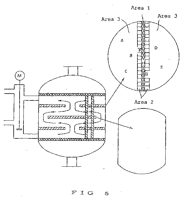
Fig. 5 is a diagram for explaining Example 6 of the
present invention.
Fig. 6(a) is a perspective view showing an
embodiment mode of a funnel used in a catalyst packing
method of the present invention.
Fig. 6(b) is a plan view of (a) seen from an A
direction.
Fig. 6(c) is a plan view of (a) seen from a B
direction.
Fig. 7(a) is a perspective view showing an
embodiment mode of a chain substance used in a catalyst
packing method of the present invention.
Fig. 7(b) is a plan view of (a) seen from an A
direction.
Fig. 7(c) is a plan view of (a) seen from a B
direction.
Fig. 8 is an enlarged view showing an embodiment
mode of a chain substance used in a catalyst packing
method of the present invention.
Best Mode for Carrying out the Invention
Hereinafter, the present invention will be further
described in detail by way of examples and comparative
examples, but the present invention is not limited by
the examples so long as not departing from the scope of
the invention.
<First Invention>
<Standard conditions>
· Reaction tubes of a fixed bed multi-tube heat-exchanger
type reactor
A pilot device of a fixed bed reactor consists of a
reaction tube which has an inner diameter of 27 mm and a
length of 5 m and is provided with a jacket for a
heating medium. The pilot device can uniformly control
temperature using niter as the heating medium.
· Former reaction catalyst (propylene vapor phase
catalytic oxidation catalyst)
A catalyst of the following composition (atomic
ratio) was prepared by a method disclosed in JP 63-054942
A as the propylene vapor phase catalytic
oxidation catalyst.
Mo:Bi:Co:Fe:Na:B:K:Si:O =
12:1:0.6:7:0.1:0.2:0.1:18:X
Wherein, X is a value determined from oxidation
states of respective metal elements.
The reaction tube was packed with 0.86 L of the
catalyst, 0.43 L of a mixture containing 70% of the
catalyst and 30% of alumina balls in volume ratio
thereon, and 0.43 L of a mixture containing 50% of the
catalyst and 50% of the alumina balls in volume ratio
further thereon.
· Former reaction conditions
A raw material gas having a composition of 9.5 mol%
of propylene, 71.9 mol% of air, and 18.6 mol% of steam
was fed to the reaction tube of the fixed bed multi-tube
reactor of the pilot device or an actual equipment at a
flow rate of 1,032 NL/H.
· Reaction pressure
An outlet pressure of a latter reactor was adjusted
to 50 KPaG (gauge pressure).
Example 1
A pressure loss of the reaction tube when feeding
air of the same volume (1,032 NL/H) as the volume of gas
fed under the standard reaction conditions was 7.1 KPa
after packing the former catalyst in the reaction tube
of the pilot device under standard conditions.
Further, reaction performance of the reaction tube
at a reaction temperature of 323°C resulted in propylene
conversion of 98.0% and total yield of acrylic acid and
acrolein of 92.1%. (Here, the reaction temperature can
also be referred to as "heating medium temperature"
because the reaction temperature can be determined from
the temperature of the heating medium circulating
outside the reaction tube for absorbing heat of reaction
generated from the reaction tube.)
Comparative Example 1
The catalyst was packed following the same method
as in Example 1 except that catalyst packing time was
changed. As a result, the pressure loss of the reaction
tube after catalyst packing was 5.6 KPa, and the volume
of air increased to reach the same pressure loss of 7.1
KPa as in Example 1 was 1,200 NL/H.
The reaction was conducted at a heating medium
temperature of 323°C following the same method as in
Example 1 except that the gas volume fed to the former
reaction tube was changed to 1,200 NL/H. The propylene
convention was 96.7% and the total yield of the acrylic
acid and the acrolein was 90.1%, resulting in a very low
conversion compared to Example 1.
Comparative Example 2
The catalyst was packed following the same method
as in Example 1 except that catalyst packing time was
changed. As a result, the pressure loss of the reaction
tube after catalyst packing was 8.4 KPa, and the volume
of air decreased to reach the same pressure loss of 7.1
KPa as in Example 1 was 920 NL/H.
The reaction was conducted at a heating medium
temperature of 323°C following the same method as in
Example 1 except that the gas volume fed to the former
reaction tube was changed to 920 NL/H. The propylene
conversion was 98.8% and the total yield of the acrylic
acid and the acrolein was 91.6%, resulting in an
excessive oxidation reaction.
Example 2
Alumina balls as an inert substance were packed
into the reaction tube of Comparative Example 1, so that
the pressure loss of the reaction tube was 7.1 KPa, the
same as in Example 1, when feeding air of the same
volume (1,032 NL/H) as the volume of gas fed under the
standard reaction conditions. The gas volume fed to the
former reactor was 1,302 NL/H, and the reaction was
conducted under the same conditions as in Example 1 at a
heating medium temperature of 323°C. As a result, the
propylene conversion was 97.9% and the total yield of
the acrylic acid and the acrolein was 92.0%,
substantially the same result as in Example 1.
Table 1 collectively shows results of Examples 1
and 2 and Comparative Examples 1 and 2.
| | Pressure loss after catalyst packing (KPa) | With or without correction of catalyst packing specification for adjusting pressure loss | Reaction temperature (°C) | Propylene conversion (%) | Total yield of acrolein and acrylic acid (%) |
| Example 1 | 7.1 | Without correction | 323 | 98.0 | 92.1 |
| Comparative Example 1 | 5.6 | Without correction | 323 | 96.7 | 90.1 |
| Comparative Example 2 | 8.4 | Without correction | 323 | 98.8 | 91.6 |
| Example 2 | 5.6 | With correction | 323 | 97.9 | 92.0 |
Effects of the pressure loss on the catalyst over
time after catalyst packing were determined using the
actual equipment.
The actual equipment was a fixed bed multi-tube
exchanger reactor having 15,000 reaction tubes. The
reaction conditions were basically the same as in
Example 1, and an average volume of the gas fed per
reaction tube was 1,250 NL/H.
8 reaction tubes packed with a catalyst in
different packed states were prepared by changing the
catalyst packing time and the catalyst packing method,
for Examples 3 to 5 and Comparative Examples 3 and 4,
respectively.
Table 2 shows the pressure loss of the reaction
tubes after catalyst packing and the pressure loss 1
year after start of the operation. Further, the
pressure losses of the 150 reaction tubes of the reactor
were measured. The results showed that an average
pressure loss was 8.5 KPa, the same value as the
pressure loss of the reaction tube in Example 3.
Table 2 also shows the pressure loss of the
reaction tubes after catalyst packing and the pressure
loss 1 year after the start of the operation in Examples
4 and 5 and Comparative Examples 3 and 4.
The volume of gas flowing through the reaction
tubes having a pressure loss higher than the average
pressure loss was smaller than the volume of the gas
flowing in the reaction tubes having the average
pressure loss. As a result, an excessive reaction
occurred, not only causing catalyst deterioration, but
also becoming a cause of coking. In Comparative Example
3 and Comparative Example 4, outlet portions of the
reaction tubes were black, causing coking, and
completely blocked. In other words, the reaction tubes
were causing yield reduction at the beginning of coking
and were completely clogged ultimately, to result in the
reaction tubes not being used effectively for the
oxidation reaction.
| | Pressure loss after catalyst packing (KPa) | With or without correction of catalyst packing specification for adjusting pressure loss | Difference with average pressure loss (%) | Pressure loss after 1 year operation (KPa) |
| Example 3 | 8.5 | Without correction | 0 | 8.6 |
| Example 4 | 9.4 | Without correction | +10 | 9.8 |
| Example 5 | 10.2 | Without correction | +20 | 11.2 |
| Comparative Example 3 | 11.1 | Without correction | +30 | Not measurable |
| Comparative Example 4 | 10.6 | Without correction | +24 | Not measurable |
Fig. 1 shows a first embodiment mode of the fixed
bed multi-tube heat-exchanger type reactor used in a
method for vapor phase catalytic oxidation of the second
invention.
Fig. 1 shows: a reactor 1; a raw material gas
introducing port (for a downflow case) or a reaction
product gas discharging port (for an upflow case) 2; a
reaction product gas discharging port (for a downflow
case) or a raw material gas introducing port (for an
upflow case) 3; a reaction tube (catalyst packed inside)
4; an upper tube plate 5; a lower tube plate 6; baffles
7, 8, and 9; a heating medium outlet nozzle 10; a
heating medium inlet nozzle 11; a heating medium inlet
line for reaction temperature adjustment 13; and a
heating medium overflow line 14.
Note that the fixed bed multi-tube heat-exchanger
type reactor in Fig. 1 has a for case of structure
passing the heating medium in an upflow direction, but
the heating medium can be obviously passed in a downflow
direction as well according to the present invention.
The raw material gas is mixed with air and/or a
diluent gas, a recycle gas, or the like, introduced from
the raw material gas introducing port (2 or 3) to the
reactor (1), and fed to the reaction tube (4) where the
catalyst is packed. The reaction product gas produced
by oxidation through a catalytic oxidation reaction
inside the reaction tube or an unreacted gas is
discharged from the reaction product gas discharging
port (3 or 2).
The heating medium is introduced from the heating
medium inlet nozzle (11) to a reactor shell by a pump
(12), passed through inside the reactor shell while
removing the heat of reaction generated inside the
reaction tube, discharged from the heating medium outlet
nozzle (10), and circulated by the pump. Temperature of
the heating medium is controlled by introducing a
cooling medium from a cooling medium nozzle (13), and
the medium introduced from the nozzle (13) is discharged
from the heating medium overflow line (14).
A structure of the baffles of the fixed bed multi-tube
heat-exchanger type reactor according to the
present invention is not particularly limited. Any type
of the fixed bed multi-tube heat-exchanger type reactor
can be used including a double segment baffle type as
shown in Fig. 2, a ring and doughnut baffle type as
shown in Fig. 3, and a multi baffle type as shown in Fig.
4, for example. In Figs. 2 to 4, shapes of the baffles
and flow of the heating medium are described.
Reference Example 1
The following experiment indicates that the
reaction tube located in a portion of poor heat removal
can be brought under the same reaction conditions as
other reaction tubes by changing the packing
specifications of the catalyst.
The fixed bed multi-tube heat-exchanger type
reactor consisting of a stainless steel reaction tube
having an inner diameter of 27 mm and a length of 5 m
was used. Partially hydrogenated triphenyl, which is an
organic heating medium, was used as a heating medium.
The fixed bed multi-tube heat-exchanger type reactor is
of a type capable of circulating the heating medium by
an external pump and controlling the volume of the
heating medium circulating.
The reaction tube was packed with a mixture
containing 80% of an Mo-V-Sb catalyst prepared following
a conventional procedure and 20% of alumina balls in
volume ratio to a height of 1.8 m and a mixture
containing 50% of the catalyst and 50% of the alumina
balls in volume ratio to a height of 1.0 m thereon.
A mixed gas consisting of 6 mol% of acrolein, 7
mol% of oxygen, 16 mol% of steam, nitrogen, or the like
were fed to the fixed bed multi-tube heat-exchanger type
reactor under a condition of a contact time of 2 seconds
at a heating medium temperature of 265°C with the
heating medium circulating at 2.5 m3/h.
An acrolein conversion, an acrylic acid yield, and
a peak temperature of the catalyst layer at this time
were respectively 99%, 97%, and 295°C.
Here, the acrolein conversion and the acrylic acid
yield were respectively determined as follows.
Acrolein conversion (mol%) = {(moles of acrolein
reacted) / (moles of acrolein fed)} x 100
Acrylic acid yield (mol%) = {(moles of acrylic acid
produced) / (moles of acrolein fed)} x 100
Further, the peak temperature of the catalyst layer
was determined by inserting a multi-point thermocouple
(20 points) to the reaction tube and measuring the
temperatures of the respective points of measurement.
Next, an experiment was conducted following the
same method as described except that the volume of the
heating medium circulating was changed to 0.5 m3/h. As a
result, the acrolein conversion, the acrylic acid yield,
and the peak temperature of the catalyst layer were
respectively 99.7%, 95.5%, and 313°C.
Next, an experiment was conducted following the
same method as described above with the volume of the
heating medium circulating remained at 0.5 m3/h except
that the packing specifications of the catalyst in the
reaction tube was changed. Here, the Mo-V-Sb catalyst
was packed to a height of 1.3 m, and a mixture
containing 40% of the catalyst and 60% of the alumina
balls in volume ratio was packed thereon to a height of
1.5 m. As a result, the acrolein conversion, the
acrylic acid yield, and the peak temperature of the
catalyst layer were respectively 99.1%, 97%, and 296°C.
The results were similar to the results of the initial
experiment circulating the heating medium at 2.5 m3/h.
The above results confirmed that a conversion, an
yield, and a peak temperature similar to those obtained
in good circulating states of the heating medium (volume
of the heating medium circulated at 2.5 m3/h) can be
attained by changing the catalyst packing specifications
in cases of poor circulating states of the heating
medium (volume of the heating medium circulated at 0.5
m3/h as described above).
Example 6
The multi-point thermocouples were provided for
measuring the catalyst layer temperatures of the
reaction tubes at positions (A to H) shown in Fig. 5
using the fixed bed multi-tube heat-exchanger type
reactor consisting of 20,000 stainless steel reaction
tubes having an inner diameter of 27 mm and a length of
3 m. The reactor shell was provided with double segment
type baffles for changing a flow path of the heating
medium. The partially hydrogenated triphenyl was used
as the heating medium.
All of the reaction tubes were packed with a
mixture containing 80% of the Mo-V-Sb catalyst, which is
the same catalyst as in Example 1, and 20% of alumina
balls in volume ratio to a height of 1.8 m and a mixture
containing 50% of the catalyst and 50% of the alumina
balls in volume ratio to a height of 1.0 m thereon. The
alumina balls were further packed thereon to upper
portions of the reaction tubes.
A mixed gas consisting of 6 mol% of acrolein, 7
mol% of oxygen, 16 mol% of steam, and the remaining
composed of mostly nitrogen and minute acrylic acid,
acetic acid, carbon dioxide, carbon monoxide, or the
like was fed to the fixed bed multi-tube heat-exchanger
type reactor under a condition of a contact time of 2.5
seconds. The temperature of the heating medium at this
time was 260°C.
Table 3 shows the peak temperatures of the catalyst
layer inside the respective reaction tubes positioned at
A to H.
| Reaction tube position | Catalyst layer peak temperature (°C) | Difference with the average peak temperature (°C) |
| A | 290 | - |
| B | 291 | - |
| C | 290 | - |
| D | 291 | - |
| E | 291 | - |
| F | 308 | 17 |
| G | 310 | 19 |
| H | 315 | 24 |
| The average peak temperature is 291°C, an average value of A to E. |
From the results of Table 3, the average peak
temperature in this case was defined as 291°C.
The acrolein conversion and the acrylic acid yield
at this time were respectively 99.2% and 95.3%.
Next, the catalyst layer peak temperatures of the
respective reaction tubes inside the reactor and the
average peak temperature were compared. The reaction
tubes having a temperature difference of more than 10°C
(the reaction tubes positioned at F, G, and H) were
plugged or the packing specifications of the catalyst
were changed therefor.
Area 1 described in Fig. 5 was a portion of the
poorest heat removal. Therefore, tops and bottoms of
the reaction tubes positioned in Area A including H were
plugged so that a reactant gas did not flow.
The packing specifications of the reaction tubes
positioned in Area 2 including F and G described in Fig.
5 were changed as follows. A mixture containing 90% of
the catalyst and 10% of the alumina balls in volume
ratio was packed to a height of 1.3 m, and a mixture
containing 40% of the catalyst and 60% of the alumina
balls in volume ratio was packed thereon to a height of
1.0 m. The alumina balls were further packed thereon to
the upper portions of the reaction tubes.
The reaction tubes positioned in Area 3 including A,
B, C, D, and E described in Fig. 5 had the catalyst
layer peak temperatures comparable to the average peak
temperature. Thus, the packing specifications were not
changed.
The raw material gas was fed to the reaction tubes
of the above specifications under the similar conditions
as described above. That is, a mixed gas consisting of
6 mol% of acrolein, 7 mol% of oxygen, 16 mol% of steam,
the remaining composed of mostly nitrogen and minute
acrylic acid, acetic acid, carbon dioxide, carbon
monoxide, or the like was fed to the fixed bed multi-tube
heat-exchanger type reactor under a condition of a
contact time of 2.5 seconds. The temperature of the
heating medium at this time was 262°C.
Table 4 shows the peak temperatures of the catalyst
layer inside the respective reaction tubes positioned at
A to H.
| Reaction tube position | Catalyst layer peak temperature (°C) | Difference with the average peak temperature (°C) |
| A | 291 | - |
| B | 292 | - |
| C | 290 | - |
| D | 291 | - |
| E | 292 | - |
| F | 293 | 2 |
| G | 292 | 1 |
| H | - | - |
| The average peak temperature is 291°C, an average value of A to E. |
From the results of Table 4, the average peak
temperature in this case was defined as 291°C. The
results confirmed that the respective reaction tubes had
the catalyst layer peak temperatures comparable to the
average peak temperature.
The acrolein conversion and the acrylic acid yield
at this time were respectively 99.1% and 96.8%.
As described above, the packing specifications of
the catalyst layers in the reaction tubes were changed
to be in similar reaction states in the same reactor.
As a result, nonuniformity of the reaction states was
reduced among the respective reaction tubes, and the
reaction states of the respective reaction tubes inside
the reactor could be made uniform.
From the above, a method for vapor phase catalytic
oxidation exhibiting satisfactory results such as
effectively preventing formation of hot spots, having
high yield of the reaction product gas, and having a
long catalyst life could be provided.
<Third Invention>
The catalyst for packing used in the following
Examples 7 to 9 was an Mo-Bi catalysts molded into
cylinders having an outer diameter of 6 mm, an inner
diameter of 2 mm, and a height of 6 mm through tablet
compression. Spherical mullite balls having an outer
diameter of 6 mm were used as an inert substance for
dilution (diluent).
According to the third invention, powdering and
degradation are defined as follow:
Example 7
The catalyst was packed in the reaction tube of the
fixed bed multi-tube reactor using a packing funnel with
a wire net shown in Fig. 6. The packing funnel had a
net mesh of 3 mm and an angle of inclination of the wire
net portion of 35°. A polyethylene bucket was set at a
lower portion of the packing funnel. 580 g of the Mo-Bi
catalyst, as a single catalyst, was allowed to fall from
the end of the packing funnel in 60 seconds. The powder
ratio and the crack ratio of the catalyst separated
below the wire net at this time were respectively 0.51%
and 1.04%, and a recovery rate of the powdered or
degraded catalyst was substantially 100%.
The recovery rate of the powdered or degraded
catalyst was obtained by removing the packed catalyst
without powdering or degrading and was represented as a
ratio with respect to the total catalyst removed
following the definitions of the 1) powder ratio and the
2) crack ratio.
Example 8
580 g of the Mo-Bi catalyst, as a single catalyst,
was allowed to fall from the end of the packing funnel
in 60 seconds under same conditions as in Example 7
except that the angle of the inclination of the wire net
portion of the packing funnel was changed to 50°. The
powder ratio and the crack ratio of the catalyst
separated below the wire net at this time were
respectively 0.6% and 0.84%, and recovery and separation
rate of the catalyst at the wire net was about 90%.
Example 9
The catalyst was packed in the reaction tube of the
fixed bed multi-tube reactor using a packing funnel with
a wire net shown in Fig. 6. The packing funnel had a
wire net mesh of 4 mm and an angle of inclination of the
wire net portion of 45°. A polyethylene bucket was set
at a lower portion of the packing funnel. 175 g of the
Mo-Bi catalyst and 220g of a diluent were allowed to
fall from the end of the packing funnel in 40 seconds.
The powder ratio and the crack ratio of the catalyst
separated below the wire net at this time were
respectively 0.51% and 1.29%, and recovery rate of the
powdered or degraded catalyst was 95%.
<Fourth invention>
Hereinafter, the catalysts for packing used in
Examples 10 to 13 were prepared as follows.
94.1 g of ammonium paramolybdate was dissolved in
400 ml of pure water by heating. Next, 7.18 g of ferric
nitrate, 25.8 g of cobalt nitrate, and 38.7 g of nickel
nitrate were dissolved in 60 ml of pure water by warming.
The two liquid mixtures were gradually mixed with
sufficient stirring.
Next, to the mixed liquid (slurry), a liquid
mixture containing 0.85 g of borax, 0.38 g of sodium
nitrate, and 0.36 g of potassium nitrate dissolved in 40
ml of pure water by warming was added and sufficiently
stirred. Then, 57.8 g of bismuth subcarbonate and 64 g
of silica were added to the slurry for mixing under
stirring. The slurry was subjected to drying by heating,
and then to heat treatment in air at 300°C for 1 hour.
The obtained solid was molded into cylinders having an
outer diameter of 6 mm, an inner diameter of 2 mm, and a
height of 6 mm through table compression using a compact
molding device. The cylinders were calcined in a muffle
furnace at 480°C for 8 hours, to thereby obtain a
catalyst. The obtained catalyst is a mixed oxide having
the following atomic ratio, which is a composition ratio
of metal components of the catalyst calculated from the
raw materials.
Mo:Bi:Co:Ni:Fe:Na:B:K:Si = 12:5:2:3:0.4:0.2:0.2:0.08:24
The obtained catalyst was an Mo-Bi catalyst molded
into cylinders having an outer diameter of 6 mm, an
inner diameter of 2 mm, and a height of 6 mm through
tablet compression. Spherical mullite balls having an
outer diameter of 6 mm were used as an inert substance
for dilution (diluent).
According to the fourth invention, powdering and
degradation are defined as follows:
Example 10
A stainless steel spring was fixed at a bottom
portion of a stainless steel straight pipe having an
inner diameter of 26.6 mm and a pipe length of 4.4 m at
a position 50 mm above the bottom portion of the
straight pipe. A stainless steel chain having a length
of 2.65 m and consisting of an oval ring member having a
wire diameter of 1.5 mm and an outer diameter of 6 mm x
9 mm was hanged (free fall distance of 1.7 m) from an
upper portion of a reaction tube. 650 g of the Mo-Bi
catalyst as a single catalyst was packed by allowing the
catalyst to fall from the upper portion. Note that a
distance between a lower end of the chain and an upper
end of the catalyst layer was 5 cm. The powder ratio
and the crack ratio at this time were respectively 0.2%
and 3.1%.
Comparative Example 5
650 g of the Mo-Bi catalyst as a single catalyst
was packed by allowing the catalyst to fall as in
Example 10 except that a chain was not used (free fall
distance of 4.35 m). The powder ratio and the crack
ratio at this time were respectively 0.9% and 25.0%.
Example 11
A stainless steel spring was fixed in the reaction
tube of the Example 10 at a position 1.55 m above the
bottom portion of the reaction tube. A chain having a
length of 1.85 m was hanged (free fall distance of 1.0
m) from the upper portion of the reaction tube. A
diluent catalyst containing 195 g of the Mo-Bi catalyst
and 240 g of the diluent mixed was packed by allowing
the catalyst to fall from the upper portion. Note that
a distance between the lower end of the chain and the
upper end of the catalyst layer was 5 cm. The powder
ratio and the crack ratio at this time were respectively
0.4% and 4.8%.
Comparative Example 6
The diluent catalyst in Example 11 was packed by
allowing the catalyst to fall as in Example 11 except
that a chain was not inserted (free fall distance of
2.85 m). The powder ratio and the crack ratio at this
time were respectively 0.9% and 19.4%.
Example 12
A stainless steel spring was fixed in the reaction
tube of the Example 10 at a position 2.55 m above the
bottom portion of the reaction tube. A chain having a
length of 0.9 m was hanged (free fall distance of 0.95
m) from the upper portion of the reaction tube. A
diluent catalyst containing 140 g of the Mo-Bi catalyst
and 345 g of the diluent mixed was packed by allowing
the catalyst to fall from the upper portion. Note that
a distance between the lower end of the chain and the
upper end of the catalyst layer was 50 cm. The powder
ratio and the crack ratio at this time were respectively
0.3% and 5.6%.
Comparative Example 7
The diluent catalyst in Example 12 was packed by
allowing the catalyst to fall as in Example 12 except
that a chain was not inserted (free fall distance of
1.85 m). The powder ratio and the crack ratio at this
time were respectively 0.6% and 13.4%.
Example 13
A stainless steel spring was fixed at a bottom
portion of a polycarbonate straight pipe having an inner
diameter of 24.0 mm and a pipe length of 1.0 m. A chain
having a length of 0.7 m was hanged (free fall distance
of 0.3 m) from the upper portion of the reaction tube.
35 g of the Mo-Bi catalyst as a single catalyst was
packed by allowing the catalyst to fall. Note that a
distance between the lower end of the chain and the
upper end of the catalyst layer was 2 cm. The powder
ratio and the crack ratio at this time were respectively
0.3% and 0.9%.
Comparative Example 8
35 g of the Mo-Bi catalyst as a single catalyst was
packed by allowing the catalyst to fall as in Example 13
except that a chain was not inserted (free fall distance
of 1.0 m). The powder ratio and the crack ratio at this
time were respectively 0.3% and 3.0%.
Industrial Applicability
According to the first invention of the present
invention, in a method for producing acrolein and
acrylic acid, and the like from a raw material gas such
as propane and propylene through vapor phase catalytic
oxidation with molecular oxygen or a molecular oxygen-containing
gas using a fixed bed multi-tube heat-exchanger
type reactor, not only are the variations of
the reaction states among the respective reaction tubes
suppressed and is the improvement on catalyst life
achieved, but also acrolein, acrylic acid, and the like
can be produced in high yields. Such results can be
obtained by packing the catalyst in the respective
reaction tubes of the fixed bed multi-tube heat-exchanger
type reactor and then using the reactor for
reaction after adjusting the pressure loss of the
reaction tubes to be uniform.
Further, according to the second invention of the
present invention, a method for vapor phase catalytic
oxidation achieving satisfactory results such as
effectively preventing hot spot formation, yielding a
large volume of the reaction product gas, and extending
catalyst life can be provided. These satisfactory
results may be obtained by using the fixed bed multi-tube
heat-exchanger type reactor provided with a
plurality of reaction tubes, circulating a heating
medium outside the reaction tubes, and feeding the raw
material gas inside the reaction tubes packed with the
catalyst.
Further, according to the third invention of the
present invention, the use of the funnel with a net in
at least a part of the funnel for packing the catalyst
in the reaction tubes of the fixed bed multi-tube
reactor allows substantially complete separation or
removal of the powdered or degraded catalyst generated
during transfer, transport, and handling of the catalyst.
Therefore, mechanical strength of the catalyst does not
have to be increased more than necessary concerning
powdering or the like of the catalyst during packing
thereof. Limitations on catalyst design become small,
enabling catalyst preparation under a broad range of
conditions.
According to the fourth invention of the present
invention, the resistance of the chain substance can
remarkably reduce powdering or degradation of the
catalyst caused by physical impact during falling of the
catalyst, when packing the catalyst in the fixed bed
multi-tube reactor. Therefore, mechanical strength of
the catalyst does not have to be increased more than
necessary concerning powdering or the like of the
catalyst during packing thereof. Limitations on
catalyst design become small, enabling catalyst
preparation under a broad range of conditions. Further,
blocking can be prevented during catalyst packing.