EP1475678B1 - Method for producing a hologram by picosecond laser - Google Patents
Method for producing a hologram by picosecond laser Download PDFInfo
- Publication number
- EP1475678B1 EP1475678B1 EP03705133A EP03705133A EP1475678B1 EP 1475678 B1 EP1475678 B1 EP 1475678B1 EP 03705133 A EP03705133 A EP 03705133A EP 03705133 A EP03705133 A EP 03705133A EP 1475678 B1 EP1475678 B1 EP 1475678B1
- Authority
- EP
- European Patent Office
- Prior art keywords
- hologram
- laser
- beams
- workpiece
- pulse
- Prior art date
- Legal status (The legal status is an assumption and is not a legal conclusion. Google has not performed a legal analysis and makes no representation as to the accuracy of the status listed.)
- Expired - Lifetime
Links
Images


Classifications
-
- G—PHYSICS
- G02—OPTICS
- G02B—OPTICAL ELEMENTS, SYSTEMS OR APPARATUS
- G02B5/00—Optical elements other than lenses
- G02B5/18—Diffraction gratings
- G02B5/1847—Manufacturing methods
- G02B5/1857—Manufacturing methods using exposure or etching means, e.g. holography, photolithography, exposure to electron or ion beams
-
- G—PHYSICS
- G03—PHOTOGRAPHY; CINEMATOGRAPHY; ANALOGOUS TECHNIQUES USING WAVES OTHER THAN OPTICAL WAVES; ELECTROGRAPHY; HOLOGRAPHY
- G03H—HOLOGRAPHIC PROCESSES OR APPARATUS
- G03H1/00—Holographic processes or apparatus using light, infrared or ultraviolet waves for obtaining holograms or for obtaining an image from them; Details peculiar thereto
- G03H1/04—Processes or apparatus for producing holograms
-
- G—PHYSICS
- G02—OPTICS
- G02B—OPTICAL ELEMENTS, SYSTEMS OR APPARATUS
- G02B17/00—Systems with reflecting surfaces, with or without refracting elements
- G02B17/02—Catoptric systems, e.g. image erecting and reversing system
- G02B17/023—Catoptric systems, e.g. image erecting and reversing system for extending or folding an optical path, e.g. delay lines
-
- G—PHYSICS
- G03—PHOTOGRAPHY; CINEMATOGRAPHY; ANALOGOUS TECHNIQUES USING WAVES OTHER THAN OPTICAL WAVES; ELECTROGRAPHY; HOLOGRAPHY
- G03H—HOLOGRAPHIC PROCESSES OR APPARATUS
- G03H1/00—Holographic processes or apparatus using light, infrared or ultraviolet waves for obtaining holograms or for obtaining an image from them; Details peculiar thereto
- G03H1/02—Details of features involved during the holographic process; Replication of holograms without interference recording
- G03H1/024—Hologram nature or properties
- G03H1/0244—Surface relief holograms
-
- G—PHYSICS
- G03—PHOTOGRAPHY; CINEMATOGRAPHY; ANALOGOUS TECHNIQUES USING WAVES OTHER THAN OPTICAL WAVES; ELECTROGRAPHY; HOLOGRAPHY
- G03H—HOLOGRAPHIC PROCESSES OR APPARATUS
- G03H1/00—Holographic processes or apparatus using light, infrared or ultraviolet waves for obtaining holograms or for obtaining an image from them; Details peculiar thereto
- G03H1/04—Processes or apparatus for producing holograms
- G03H1/0402—Recording geometries or arrangements
- G03H2001/0413—Recording geometries or arrangements for recording transmission holograms
-
- G—PHYSICS
- G03—PHOTOGRAPHY; CINEMATOGRAPHY; ANALOGOUS TECHNIQUES USING WAVES OTHER THAN OPTICAL WAVES; ELECTROGRAPHY; HOLOGRAPHY
- G03H—HOLOGRAPHIC PROCESSES OR APPARATUS
- G03H1/00—Holographic processes or apparatus using light, infrared or ultraviolet waves for obtaining holograms or for obtaining an image from them; Details peculiar thereto
- G03H1/04—Processes or apparatus for producing holograms
- G03H1/0402—Recording geometries or arrangements
- G03H2001/0415—Recording geometries or arrangements for recording reflection holograms
-
- G—PHYSICS
- G03—PHOTOGRAPHY; CINEMATOGRAPHY; ANALOGOUS TECHNIQUES USING WAVES OTHER THAN OPTICAL WAVES; ELECTROGRAPHY; HOLOGRAPHY
- G03H—HOLOGRAPHIC PROCESSES OR APPARATUS
- G03H1/00—Holographic processes or apparatus using light, infrared or ultraviolet waves for obtaining holograms or for obtaining an image from them; Details peculiar thereto
- G03H1/04—Processes or apparatus for producing holograms
- G03H1/0476—Holographic printer
- G03H2001/0482—Interference based printer
-
- G—PHYSICS
- G03—PHOTOGRAPHY; CINEMATOGRAPHY; ANALOGOUS TECHNIQUES USING WAVES OTHER THAN OPTICAL WAVES; ELECTROGRAPHY; HOLOGRAPHY
- G03H—HOLOGRAPHIC PROCESSES OR APPARATUS
- G03H1/00—Holographic processes or apparatus using light, infrared or ultraviolet waves for obtaining holograms or for obtaining an image from them; Details peculiar thereto
- G03H1/04—Processes or apparatus for producing holograms
- G03H1/0476—Holographic printer
- G03H2001/0484—Arranged to produce three-dimensional fringe pattern
-
- G—PHYSICS
- G03—PHOTOGRAPHY; CINEMATOGRAPHY; ANALOGOUS TECHNIQUES USING WAVES OTHER THAN OPTICAL WAVES; ELECTROGRAPHY; HOLOGRAPHY
- G03H—HOLOGRAPHIC PROCESSES OR APPARATUS
- G03H1/00—Holographic processes or apparatus using light, infrared or ultraviolet waves for obtaining holograms or for obtaining an image from them; Details peculiar thereto
- G03H1/04—Processes or apparatus for producing holograms
- G03H1/0486—Improving or monitoring the quality of the record, e.g. by compensating distortions, aberrations
- G03H2001/0491—Improving or monitoring the quality of the record, e.g. by compensating distortions, aberrations by monitoring the hologram formation, e.g. via a feed-back loop
-
- G—PHYSICS
- G03—PHOTOGRAPHY; CINEMATOGRAPHY; ANALOGOUS TECHNIQUES USING WAVES OTHER THAN OPTICAL WAVES; ELECTROGRAPHY; HOLOGRAPHY
- G03H—HOLOGRAPHIC PROCESSES OR APPARATUS
- G03H2222/00—Light sources or light beam properties
- G03H2222/33—Pulsed light beam
-
- G—PHYSICS
- G03—PHOTOGRAPHY; CINEMATOGRAPHY; ANALOGOUS TECHNIQUES USING WAVES OTHER THAN OPTICAL WAVES; ELECTROGRAPHY; HOLOGRAPHY
- G03H—HOLOGRAPHIC PROCESSES OR APPARATUS
- G03H2223/00—Optical components
- G03H2223/26—Means providing optical delay, e.g. for path length matching
-
- G—PHYSICS
- G03—PHOTOGRAPHY; CINEMATOGRAPHY; ANALOGOUS TECHNIQUES USING WAVES OTHER THAN OPTICAL WAVES; ELECTROGRAPHY; HOLOGRAPHY
- G03H—HOLOGRAPHIC PROCESSES OR APPARATUS
- G03H2240/00—Hologram nature or properties
- G03H2240/20—Details of physical variations exhibited in the hologram
- G03H2240/23—Optical length variations, e.g. bleached silver halide
- G03H2240/24—Index variations only
-
- G—PHYSICS
- G03—PHOTOGRAPHY; CINEMATOGRAPHY; ANALOGOUS TECHNIQUES USING WAVES OTHER THAN OPTICAL WAVES; ELECTROGRAPHY; HOLOGRAPHY
- G03H—HOLOGRAPHIC PROCESSES OR APPARATUS
- G03H2260/00—Recording materials or recording processes
- G03H2260/50—Reactivity or recording processes
- G03H2260/62—Direct etching
-
- G—PHYSICS
- G03—PHOTOGRAPHY; CINEMATOGRAPHY; ANALOGOUS TECHNIQUES USING WAVES OTHER THAN OPTICAL WAVES; ELECTROGRAPHY; HOLOGRAPHY
- G03H—HOLOGRAPHIC PROCESSES OR APPARATUS
- G03H2270/00—Substrate bearing the hologram
- G03H2270/10—Composition
- G03H2270/13—Metallic
-
- G—PHYSICS
- G03—PHOTOGRAPHY; CINEMATOGRAPHY; ANALOGOUS TECHNIQUES USING WAVES OTHER THAN OPTICAL WAVES; ELECTROGRAPHY; HOLOGRAPHY
- G03H—HOLOGRAPHIC PROCESSES OR APPARATUS
- G03H2270/00—Substrate bearing the hologram
- G03H2270/52—Integrated surface relief hologram without forming layer
Definitions
- the present invention relates to a method of producing a micro-hologram in a transparent compound, semiconductor, organic material or metal, using interfering laser pulses with high energy density.
- a method of preparing holographic optical elements or diffraction grating elements by utilizing the interference between laser beams is one of well-known techniques commonly used for years.
- the diffraction gratings produced by the interfering laser exposure are applied to various devices, such as spectrometer, distributed feedback semiconductor lasers or fiber grating devices.
- the laser for use in the production process of such diffraction gratings includes a He-Cd laser, an argon ion laser, an excimer laser, a continuous wave laser or a nanosecond pulsed laser. These lasers can emit a beam with a relatively low energy density, and thereby a material to be processed is required to have photosensitivity.
- the inventors previously developed a method of producing holographic optical elements by utilizing the interference between femtosecond leaser beams.
- the femtosecond laser beams having a high energy density makes it possible to record a diffractive grating in almost all materials without the need for photosensitivity in a material to be processed.
- the femtosecond pulsed beam having an excessively high energy at a pulse peak causes increase in the non-linear optical interaction of the beam with air and a hologram-recording material, resulting in difficulties in stably recording a hologram.
- the conventional process of recording a pure irreversible hologram in a non-photosensitive material using interfering femtosecond laser pulses involves a problem concerning the distortion in the waveforms of pulsed laser beams due to a non-linear optical interaction between the femtosecond laser pulses and air/the material. Such instability makes it very difficult to record an embedded hologram.
- the method of the present invention uses a pulsed laser light obtained by increasing the pulse width ( ⁇ ) of a femtosecond pulsed laser light to the range from greater than 1 picosecond to 10 picoseconds (hereinafter this laser pulse is referred to as "picosecond pulse”), while maintaining the integrated laser energy of the femtosecond pulsed laser light, through the use of a technique of relaxing the phase matching of a femtosecond pulsed laser light based on chirping, so as to allow an embedded hologram to be recorded with excellent reproducibility through an interfering two-beam laser exposure technique.
- picosecond pulse a pulsed laser light obtained by increasing the pulse width ( ⁇ ) of a femtosecond pulsed laser light to the range from greater than 1 picosecond to 10 picoseconds
- the pulse width is increased while maintaining energy per pulse at a constant value.
- the peak value of the laser energy is lowered so that the non-linear optical interaction between the pulsed laser light and a material is suppressed so as to reduce the distortion in waveform of the pulsed laser light even during propagation through the material to allow an embedded hologram to be stably recorded inside the material.
- a method of recording an embedded hologram using interfering femtosecond laser beams has already been proposed by the inventors.
- the present invention is intended to improve this method so as to provide a method of recording an embedded hologram in any depth of a material and a method of recording the hologram in a multiple encoding, based on a pulsed laser light having a pulse width increased to the range from greater than 1 picosecond to 10 picoseconds.
- the present invention may be applied to a method of forming 1-dimensional or 2-dimensional hologram embedded in a material, and a method of forming one or more holograms within a single or common material, based on interfering pulsed laser beams to be emitted onto the material.
- the present invention provides method of producing a hologram through a two-beam laser exposure process, as set forth in claim 1. Preferred embodiments of the present invention may be gathered from the dependent claims.
- the inventors developed a two-beam laser interfering exposure process using a femtosecond laser to achieve a method capable of recording a hologram in an organic material, inorganic material, semiconductor material or metal material which originally has no photosensitivity, by use of a pair of femtosecond pulsed beams divided from a single fs pulsed laser light, and filed a patent application (Japanese Patent Laid-Open Publication No. 2001-236002 , EP 1,162,519 ).
- This hologram encoding method through the two-beam laser interfering exposure process comprises a pulsed laser light from a light source consisting of a solid-state femtosecond laser capable of generating a pulsed laser light equal or close to the Fourier transform limit, with an oscillation wavelength of about 800 nm in the near-infrared region, a pulse width ⁇ ranging from greater than 10 femtoseconds to 900 femtosecond, and a peak power of 1 GW or more, dividing the pulsed laser light into two beams using a beam splitter, and converging the two beams on a surface of or inside a workpiece for recording a hologram, at an energy density of 100 GW/cm 2 or more while temporally controlling the two beams through an optical delay circuit and spatially controlling the two beams using a mirror having a finely rotatable flat or concave reflection surface in such a manner that the converged spots of the two beams are matched with one another tempor
- the laser energy is first absorbed by electrons in the material. It is believed that a time of about 100 picoseconds is required for allowing the energy of the electrons to be converted into the vibration energy of atoms in the material or the vibration energy of atoms constituting the workpiece or the heat energy of the workpiece. Then, when the density of the electron energy goes beyond a given threshold value, the resulting ablation or structural change in the workpiece causes an irreversible change in the workpiece.
- the interference pattern will be transferred to the material or an irreversible hologram is recorded in the workpiece.
- the energy to be stored in the electron system is dependent only on the entire energy of a laser pulse, but not on the width of the laser pulse.
- the laser pulse width ⁇ becomes greater than about 100 picoseconds, the energy of the electron system is relaxed or absorbed in the lattice system even during laser irradiation, and the energy to be stored in the electron system is dependent on the width of the irradiated laser pulse.
- the energy peak value of the laser pulses is provided by Et / ⁇ , and the influence of the optical non-linear interaction, or deformation in the waveform of the laser pulse during propagation, is reduced as the energy peak value is lowered.
- the laser pulse width is increased from the level of femtoseconds to the level of 10 picoseconds while maintaining the entire laser energy Et at a constant value, a hologram can be stably recorded. Further, in case of recording a hologram embedded in a material, the pulsed laser beams should be propagated through the material.
- an embedded hologram can be encoded in a depth of 10 ⁇ m or more from the surface of the material.
- the generation of harmonics from air or non-linear optical crystals is significantly reduced due to the lowered peak energy of the leaser pulses, and thereby it is difficult to achieve the spatial and temporal matching between the two pulsed laser beams based on the above principle.
- femtosecond laser beams having a high peak energy are first used to achieve spatial and temporal matching therebetween, and then the laser pulse width ⁇ is expanded keeping the optical configuration unchanged through a process of relaxing the phase matching of a laser light based on chirping. In this manner, the temporal and spatial matching can be maintained even between the picosecond pulses to allow an embedded hologram to be recorded.
- a diffraction grating is written in an optical fiber or an optical waveguide, it is required to write the diffraction grating in a core region on the inside of a cladding layer at an embedding depth of 10 ⁇ m to 2 mm.
- the embedding depth can be freely controlled by the converged spots to eliminate any restriction on the embedding depth.
- these lights are propagated through the laser medium, their propagation velocity is varied according to wavelength because of the wavelength dependence of the refractive index. That is, while the laser resonator has a fixed physical length, its optical length is varied depending on wavelength.
- the round-trip time of the resonator is also varied depending on wavelength. The difference in the round-trip time of the resonator depending on wavelength can be completely cancelled for all of the wavelengths, through a phase-compensation technique using a prism or the like. This state is referred to as "mode lock".
- the temporal width of a mode-locked laser pulse is in the level of picoseconds.
- a femtosecond laser pulses can also be obtained by using a laser medium having a wide bandwidth of the gain, such as titanium-sapphire.
- a phase-compensation circuit incorporated in a femtosecond laser resonator can be reversely operated to increase the temporal pulse width ⁇ to the range from greater than 900 femtoseconds to 1 picosecond. This state is referred to as "wavelength chirping".
- phase-compensation circuit pulse compensation circuit
- a phase-compensation circuit incorporated in a regenerative amplifier can be adjusted to create a wavelength chirping so as to vary the pulse width ⁇ in the range from greater than 900 femtoseconds to 100 picoseconds without reducing the total energy per pulse.
- the expansion of the pulse width ⁇ can be performed before the laser light is divided into the two laser beams using interfering exposure optical system. Thus, even if the pulse width ⁇ is expanded through the chirping technique, the state of the temporal and spatial matching will not he changed. While a hologram may be recorded in the pulse width range of greater than 900 femtoseconds to 100 picoseconds, according to the present invention the pulse width ⁇ is set to the range from greater than 1 picosecond to 10 picoseconds.
- FIG. 1 is a schematic diagram showing a laser interfering exposure apparatus for use in a method of the present invention.
- a laser light emitted from femtosecond/picosecond laser light source is reflected by a flat plane mirror M1, and then divided into a beam B1 and a beam B2 by a half mirror HF1 serving as a beam splitter.
- the beam B1 is reflected by a flat mirror M2 and a concave mirror M3, and converged on a surface of or within a workpiece S1.
- a combination of a flat mirror and a thin lens L1 may be used as a substitute for the concave mirror M3.
- the beam B2 is reflected by a flat mirror M4, a flat mirror M5 and a concave mirror M6, and converged on the surface of or within the workpiece S1.
- a combination of a lens L2 and a flat mirror may be used as a substitute for the concave mirror M6.
- An optical path indicated by the solid line is used in producing a transmission hologram. Otherwise, an optical system indicated by the thick dotted line is used in producing a reflection hologram.
- the beam B2 reflected by the concave mirror 6 is converged within the workpiece using the flat mirror M7 and the flat mirror M8.
- a combination of the lens L2 and a flat mirror may be used as a substitute for the concave mirror M6.
- a hologram formation process may be monitored by reflecting a He-Ne laser light by a flat mirror M9 toward the workpiece S1, and detecting a reflected light from the workpiece S1.
- the flat mirror M4 and the flat mirror M5 serve as an optical delay circuit. Specifically, each of the flat mirror M4 and the flat mirror M5 is finely moved in the level of 1 ⁇ m using a micrometer caliper to adjust the difference between the respective optical path lengths of the beam B1 and the beam B2 so as to temporally match the converged spots of the two beams with one another. Further, the converged spots of the two beams are positionally or spatially matched with one another by finely rotating either one of the concave mirror M3, the concave mirror M6 and the flat mirror M8 using a micrometer caliper.
- each of the lenses L1 and L2 is preferably designed to have a minimized thickness and a long focal distance.
- the beam polarization plane at the workpiece is parallel.
- An optical parameter such as the fringe interval of a diffraction grating to be formed, or a focal distance in case where the optical system has a lens function, can be determined in the same manner as that in the conventional two-beam laser interfering exposure using a continuous wave laser light.
- the workpiece S1 is placed on an X-Y stage, and finely moved using a micrometer caliper to allow a hologram to be recorded at a designated position of the workpiece.
- the two-beam laser interfering exposure apparatus is required to have an optical system capable of performing a positional adjustment in ⁇ m scale.
- the two beams are converged on the surface of or within the workpiece using the optical system having the finely controllable optical delay circuit, the finely rotatable plane and concave mirrors and the function for detecting the convergence/matching of the two beams, so as to allow the two converged spots to be matched with one another temporally and spatially.
- the temporal and spatial matching can be obtained by adjusting the optical relay circuit while monitoring the intensity of a third harmonic generation (THG) induced by the third-order non-linear effects of air, to maximize the intensity.
- a non-linear optical crystal may be used to utilize a second harmonic generation (SHG) therefrom.
- the optical delay circuit and the beam-converging optical system are adjusted while monitoring the intensity of either one of a third harmonic generation (THG) induced by the third-order non-linear effects of air, and a second harmonic generation (SHG) induced by a non-linear optical crystal, to match the two converged beams with one another temporally and spatially so as to create the interference therebetween.
- THG third harmonic generation
- SHG second harmonic generation
- a fiber laser and a solid-state laser oscillating in near-infrared light may also be used.
- the workpiece is placed on a stage, and designed to be finely moved in the level of ⁇ m and finely rotated in the level of arcminutes to allow the converged spots of the two beams to be matched at a designated position. Further, the workpiece may be observed using an optical microscope to detect a specific position within the workpiece.
- the workpiece After the temporal/spatial matching of the two beams, the workpiece is positioned at the matched spot.
- the femtosecond pulsed laser light of the mode-lock titanium-sapphire laser is regeneratively amplified to create a femtosecond pulsed laser light with a maximum energy of about 1 mj and a temporal width of about 100 femtoseconds.
- the workpiece may be made of a material selected from the group consisting of silica glass, BK 5 glass, multi-component glass, MgO, LiNbO 3 , Al 2 O 3 , ZnS, ZnSe, ZnO, YSZ (yttria stabilized zirconia), AlN, GaN, AlAs and GaAs, and mixtures thereof, and formed in bulk or thin-film to produce an embedded hologram therein.
- the workpiece made of a material selected from the group consisting of silica glass, BK 5 glass, multi-component glass, MgO, LiNbO 3 , Al 2 O 3 , ZnS, ZnSe, ZnO, YSZ (yttria stabilized zirconia), AlN, GaN, AlAs and GaAs, and mixtures thereof, and formed in bulk or thin-film may also be used to produce a surface-relief hologram therein.
- the workpiece may be made of a metal material selected from the group consisting of gold, silver, platinum, copper, nickel, chromium, aluminum, cadmium, tantalum, hard metal and metal-silicon to produce a surface-relief hologram therein
- the laser pulse ⁇ is expanded up to the range from greater than 900 femtoseconds to 100 picoseconds using the wavelength chirping technique for relaxing the phase compensation, while maintain the optical parts configuration unchanged.
- a hologram with a diameter of about 100 ⁇ m is recorded in the workpiece placed at the matched spot of the two beams, in one cycle of the pulsing operation.
- the matched spot of the interfering picosecond laser beams is positioned on the surface of the workpiece so as to form a surface-relief hologram on the workpiece.
- the laser pulse width ⁇ can be expanded to increase the depth of the fringe groove of the surface-relief hologram so as to provide enhanced diffraction efficiency of the surface-relief hologram.
- the matched spot may be positioned inside the workpiece to record an embedded hologram.
- the phase compensator (pulse compression device) in the regenerative amplifier is adjusted to vary the pulse width ⁇ in the range from greater than 900 femtoseconds to 100 picoseconds so as to determine a specific temporal width suitable for the recording of the hologram.
- the pulse width is preferably set at about 2 picoseconds.
- the workpiece may be moved in the longitudinal/lateral directions, and irradiated with interfering pulsed laser beams to record a plurality of holograms aligned in the depth direction or in the in-plane direction of the workpiece.
- the workpiece may be rotated, and irradiated with interfering pulsed laser beams to record a 2-dimensional embedded hologram therein.
- the two-beam laser interfering exposure apparatus illustrated in FIG 1 was used. That is, a laser was the regenerative-amplifier titanium-sapphire laser for generating a pulsed laser light with an oscillation center frequency of about 800 nm, a pulse width ⁇ of about 100 femtoseconds, and a pulse energy of 50 pJ/pulse for each of the two beams.
- the pulsed laser light was divided into two beams by the half mirror HF1, and converged by the lens L1 and the lens L2.
- An optical delay circuit and an optical-path positioning circuit were interposed in one of the optical paths for the beam B1 and the beam B2, and the converged spots of the two beams were matched with one another temporally and spatially according to the intensity of a third harmonic generation wave induced by air.
- the size of the matched spot was about 100 ⁇ m, and the peak density was calculated as about 1 J/cm 2 .
- the incident angle of the beams B1 and B2 at the workpiece S1 was set at 45-degree.
- a pulse-width compression optical circuit in a regenerative amplifier of the titanium-sapphire laser was adjusted while maintaining the optical circuit in the same state, to create a chirping so as to increase the pulse width ⁇ up to the range from greater than 100 femtoseconds to 2 picoseconds while maintaining the energy/pulse at 100 ⁇ J.
- the two beams were matched at the matched spot temporally and spatially.
- a silica-glass workpiece was positioned to allow the matched spot to be located at a depth of about 100 ⁇ m from the surface of the workpiece, and irradiated with the picosecond pulsed laser beams one time.
- the inside of the silica glass was observed using an optical microscope while changing a focal depth, and verified that a micro-hologram with a diameter of about 100 ⁇ m is recorded inside the silica glass.
- the silica glass was cut along the portion having the hologram recorded therein, and the section of the cut piece was etched with a hydrofluoric acid solution.
- FIGS. 2A and 2B show a scanning electron microscope (SEM) image of the etched section. It could be observed that a hologram having a thickness of about 70 ⁇ m is embedded at a depth of about 100 ⁇ m from the surface of the silica glass.
- SEM scanning electron microscope
- the depth When the depth is greater than about 50 ⁇ m, the diameter of the laser beams having energy greater than the threshold becomes smaller, and thereby the diameter of the hologram is gradually reduced.
- the embedding depth could be extended up to about 2 mm by moving the silica-glass workpiece or displacing the focal position of the picosecond laser beams in the silica-glass workpiece.
- the above result shows that a hologram with a diameter of about 100 ⁇ m, a thickness of about 70 ⁇ m can be recorded up to an embedding depth of about 2 mm from the surface of silica glass by the irradiation of interfering picosecond pulsed laser beams.
- the two-beam laser interfering exposure apparatus illustrated in FIG. 1 was used. That is, a laser was the regenerative-amplifier titanium-sapphire laser for generating a pulsed laser light with an oscillation center frequency of about 800 nm, a pulse width ⁇ of about 100 femtoseconds, and a pulse energy of 50 ⁇ J/pulse for each of the two beams.
- the pulsed laser light was divided into two beams by the half mirror HF1, and converged by the lens L1 and the lens L2.
- An optical delay circuit and an optical-path positioning circuit were interposed in one of the optical paths for the beam B1 and the beam B2, and the converged spots of the two beams were matched with one another temporally and spatially according to the intensity of the third harmonic generation wave induced by air.
- the size of the matched spot was about 100 ⁇ m, and the peak density was calculated as about 1 J/cm 2 .
- the incident angle of the beams B1 and B2 at the workpiece was set at 45-degree.
- a pulse-width compression optical circuit in a regenerative amplifier of the titanium-sapphire laser was adjusted while maintaining the optical circuit in the same state, to create a chirping so as to increase the pulse width ⁇ up to the range from greater than 100 femtoseconds to 2 picoseconds while maintaining the energy/pulse at 100 ⁇ J.
- the two beams were matched at the matched spot temporally and spatially.
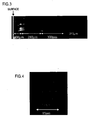
- a silica-glass workpiece was positioned to allow the matched spot to be located at a depth of about 100 ⁇ m from the surface of the workpiece, and irradiated with the picosecond pulsed laser beams one time. Further, after the workpiece was moved vertically by about 300 ⁇ m, and then irradiated with the picosecond pulsed laser beams one time. According to observation using an optical microscope, it was proved that three holograms were recorded in the vertical direction in a multiple manner. A sectional SEM image of these holograms is shown in FIG 3 . It was verified that three holograms were recorded at embedding depths of 100 ⁇ m, 380 ⁇ m and 680 ⁇ m, respectively.
- the two-beam laser interfering exposure apparatus illustrated in FIG. 1 was used. That is, a laser was the regenerative-amplifier titanium-sapphire laser for generating a pulsed laser light with an oscillation center frequency of about 800 nm, a pulse width ⁇ of about 100 femtoseconds, and a pulse energy of 50 ⁇ J/pulse for each of the two beams.
- the pulsed laser light was divided into two beams by the half mirror HF1, and converged by the lens L1 and the lens L2.
- An optical delay circuit and an optical-path positioning circuit were interposed in one of the optical paths for the beam B1 and the beam B2, and the converged spots of the two beams were matched with one another temporally and spatially according to the intensity of the third harmonic generation wave induced by air.
- the size of the matched spot was about 100 ⁇ m, and the peak density was calculated as about 1J/cm 2 .
- the incident angle of the beams B1 and B2 at the workpiece was set at 45-degree.
- a pulse-width compression optical circuit in a regenerative amplifier of the titanium-sapphire laser was adjusted while maintaining the optical circuit in the same state, to create a chirping so as to increase the pulse width ⁇ up to the range from greater than 100 femtoseconds to 2 picoseconds while maintaining the energy/pulse at 100 ⁇ J.
- the two beams were matched at the matched spot temporally and spatially.
- a silica-glass workpiece was positioned to allow the matched spot to be located at a depth of about 100 ⁇ m from the surface of the workpiece, and irradiated with the picosecond pulsed laser beams one time. Then, after the silica-glass workpiece was rotated by 90-degree, the position of the silica glass workpiece was adjusted to allow the matched spot to be overlapped with the recorded hologram, and then irradiated with the picosecond pulsed laser beams one time. According to observation using an optical microscope, a 2-dimensional hologram image as shown in FIG. 4 could be observed when the focal depth was displaced by about 100 ⁇ m from the surface of the silica glass workpiece.
- FIG. 4 is a photograph showing a scanning electron microscope (SEM) image of the section of the hologram. This result shows that a 2-dimensional embedded hologram can be recorded by the double irradiation of interfering picosecond pulsed laser beams.
- SEM scanning electron microscope
Landscapes
- Physics & Mathematics (AREA)
- General Physics & Mathematics (AREA)
- Engineering & Computer Science (AREA)
- Manufacturing & Machinery (AREA)
- Optics & Photonics (AREA)
- Holo Graphy (AREA)
- Laser Beam Processing (AREA)
- Diffracting Gratings Or Hologram Optical Elements (AREA)
Abstract
Description
- The present invention relates to a method of producing a micro-hologram in a transparent compound, semiconductor, organic material or metal, using interfering laser pulses with high energy density.
- A method of preparing holographic optical elements or diffraction grating elements by utilizing the interference between laser beams is one of well-known techniques commonly used for years. The diffraction gratings produced by the interfering laser exposure are applied to various devices, such as spectrometer, distributed feedback semiconductor lasers or fiber grating devices. The laser for use in the production process of such diffraction gratings includes a He-Cd laser, an argon ion laser, an excimer laser, a continuous wave laser or a nanosecond pulsed laser. These lasers can emit a beam with a relatively low energy density, and thereby a material to be processed is required to have photosensitivity. The inventors previously developed a method of producing holographic optical elements by utilizing the interference between femtosecond leaser beams.
- In this method, the femtosecond laser beams having a high energy density makes it possible to record a diffractive grating in almost all materials without the need for photosensitivity in a material to be processed. However, the femtosecond pulsed beam having an excessively high energy at a pulse peak causes increase in the non-linear optical interaction of the beam with air and a hologram-recording material, resulting in difficulties in stably recording a hologram.
- Particularly, in the process of forming an embedded hologram in the inside of a material, it is essential to propagate laser pulses with a high energy through the material, and the waveform of the laser pulses is liable to be irregularly deformed. Thus, in order to suppress such a distortion, it is required to select a specific material, or set the laser energy just below the threshold value for the encoding for recording and allowing the influence of the non-linear optical interaction to be ignored. However, the acceptable energy range of the laser pulse is narrow, and it is extremely difficult to record a hologram having a desired performance.
- As mentioned above, the conventional process of recording a pure irreversible hologram in a non-photosensitive material using interfering femtosecond laser pulses involves a problem concerning the distortion in the waveforms of pulsed laser beams due to a non-linear optical interaction between the femtosecond laser pulses and air/the material. Such instability makes it very difficult to record an embedded hologram.
- In view of this problem, it is an object of the present invention to provide a method recording an embedded hologram using mutually-interfering laser beams with a pulse width (τ) in a picosecond (10-12 sec) range which is obtained by chirping a femtosecond pulsed laser. The method of the present invention uses a pulsed laser light obtained by increasing the pulse width (τ) of a femtosecond pulsed laser light to the range from greater than 1 picosecond to 10 picoseconds (hereinafter this laser pulse is referred to as "picosecond pulse"), while maintaining the integrated laser energy of the femtosecond pulsed laser light, through the use of a technique of relaxing the phase matching of a femtosecond pulsed laser light based on chirping, so as to allow an embedded hologram to be recorded with excellent reproducibility through an interfering two-beam laser exposure technique.
- In the method of the present invention, the pulse width is increased while maintaining energy per pulse at a constant value. Thus, the peak value of the laser energy is lowered so that the non-linear optical interaction between the pulsed laser light and a material is suppressed so as to reduce the distortion in waveform of the pulsed laser light even during propagation through the material to allow an embedded hologram to be stably recorded inside the material.
- A method of recording an embedded hologram using interfering femtosecond laser beams has already been proposed by the inventors. The present invention is intended to improve this method so as to provide a method of recording an embedded hologram in any depth of a material and a method of recording the hologram in a multiple encoding, based on a pulsed laser light having a pulse width increased to the range from greater than 1 picosecond to 10 picoseconds.
- The present invention may be applied to a method of forming 1-dimensional or 2-dimensional hologram embedded in a material, and a method of forming one or more holograms within a single or common material, based on interfering pulsed laser beams to be emitted onto the material.
- Specifically, the present invention provides method of producing a hologram through a two-beam laser exposure process, as set forth in claim 1. Preferred embodiments of the present invention may be gathered from the dependent claims.
- In place of a conventional method of producing a hologram using a photosensitive material through a two-beam laser exposure process, the inventors developed a two-beam laser interfering exposure process using a femtosecond laser to achieve a method capable of recording a hologram in an organic material, inorganic material, semiconductor material or metal material which originally has no photosensitivity, by use of a pair of femtosecond pulsed beams divided from a single fs pulsed laser light, and filed a patent application (Japanese Patent Laid-Open Publication No.
2001-236002 EP 1,162,519 ). - This hologram encoding method through the two-beam laser interfering exposure process comprises a pulsed laser light from a light source consisting of a solid-state femtosecond laser capable of generating a pulsed laser light equal or close to the Fourier transform limit, with an oscillation wavelength of about 800 nm in the near-infrared region, a pulse width τ ranging from greater than 10 femtoseconds to 900 femtosecond, and a peak power of 1 GW or more, dividing the pulsed laser light into two beams using a beam splitter, and converging the two beams on a surface of or inside a workpiece for recording a hologram, at an energy density of 100 GW/cm2 or more while temporally controlling the two beams through an optical delay circuit and spatially controlling the two beams using a mirror having a finely rotatable flat or concave reflection surface in such a manner that the converged spots of the two beams are matched with one another temporally and spatially, so as to record a hologram in the workpiece consisting of a transparent material, a semiconductor material or metal material in an irreversible manner, based on ablation of the workpiece and/or structural change in the atomic arrangement of the workpiece and/or change in the refractive index of the workpiece which are caused by the high energy irradiation.
- When the material is irradiated with a pulsed laser beam having high energy, the laser energy is first absorbed by electrons in the material. It is believed that a time of about 100 picoseconds is required for allowing the energy of the electrons to be converted into the vibration energy of atoms in the material or the vibration energy of atoms constituting the workpiece or the heat energy of the workpiece. Then, when the density of the electron energy goes beyond a given threshold value, the resulting ablation or structural change in the workpiece causes an irreversible change in the workpiece. In this case, if the laser energy per area is set such that the density of the electron energy in the boundary between the bright and dark portions in the interference pattern is equal to the threshold value, the interference pattern will be transferred to the material or an irreversible hologram is recorded in the workpiece.
- That is, in the state before the duration of the laser pulse reaches about 100 picoseconds, the energy to be stored in the electron system is dependent only on the entire energy of a laser pulse, but not on the width of the laser pulse. In contrast, when the laser pulse width τ becomes greater than about 100 picoseconds, the energy of the electron system is relaxed or absorbed in the lattice system even during laser irradiation, and the energy to be stored in the electron system is dependent on the width of the irradiated laser pulse. More specifically, a laser energy to be effectively used in recording a hologram Ef is expressed by the following formula:

- Further, the energy peak value of the laser pulses is provided by Et / τ, and the influence of the optical non-linear interaction, or deformation in the waveform of the laser pulse during propagation, is reduced as the energy peak value is lowered. Thus, if the laser pulse width is increased from the level of femtoseconds to the level of 10 picoseconds while maintaining the entire laser energy Et at a constant value, a hologram can be stably recorded. Further, in case of recording a hologram embedded in a material, the pulsed laser beams should be propagated through the material. Thus, by setting the effective energy Ef at a value equal to or greater than the threshold value, and by encoding the pulse width τ up to about 10 picoseconds, thereby reducing the distortion of the waveform due to the propagation through the materia, l an embedded hologram can be encoded in a depth of 10 µm or more from the surface of the material.
- In the picosecond pulses, the generation of harmonics from air or non-linear optical crystals is significantly reduced due to the lowered peak energy of the leaser pulses, and thereby it is difficult to achieve the spatial and temporal matching between the two pulsed laser beams based on the above principle. Thus, femtosecond laser beams having a high peak energy are first used to achieve spatial and temporal matching therebetween, and then the laser pulse width τ is expanded keeping the optical configuration unchanged through a process of relaxing the phase matching of a laser light based on chirping. In this manner, the temporal and spatial matching can be maintained even between the picosecond pulses to allow an embedded hologram to be recorded. In case where a diffraction grating is written in an optical fiber or an optical waveguide, it is required to write the diffraction grating in a core region on the inside of a cladding layer at an embedding depth of 10 µm to 2 mm. In the method of the present invention, the embedding depth can be freely controlled by the converged spots to eliminate any restriction on the embedding depth.
- A plurality of wavelength components exist in a laser resonator because the gain of a laser medium includes a certain width in wavelength. When these lights are propagated through the laser medium, their propagation velocity is varied according to wavelength because of the wavelength dependence of the refractive index. That is, while the laser resonator has a fixed physical length, its optical length is varied depending on wavelength. Thus, the round-trip time of the resonator is also varied depending on wavelength. The difference in the round-trip time of the resonator depending on wavelength can be completely cancelled for all of the wavelengths, through a phase-compensation technique using a prism or the like. This state is referred to as "mode lock".
- When the bandwidth as the gain of the laser medium is small, the temporal width of a mode-locked laser pulse is in the level of picoseconds. At the same time, a femtosecond laser pulses can also be obtained by using a laser medium having a wide bandwidth of the gain, such as titanium-sapphire. Thus, a phase-compensation circuit incorporated in a femtosecond laser resonator can be reversely operated to increase the temporal pulse width τ to the range from greater than 900 femtoseconds to 1 picosecond. This state is referred to as "wavelength chirping". Further, a phase-compensation circuit (pulse compensation circuit) incorporated in a regenerative amplifier can be adjusted to create a wavelength chirping so as to vary the pulse width τ in the range from greater than 900 femtoseconds to 100 picoseconds without reducing the total energy per pulse.
- The expansion of the pulse width τ can be performed before the laser light is divided into the two laser beams using interfering exposure optical system. Thus, even if the pulse width τ is expanded through the chirping technique, the state of the temporal and spatial matching will not he changed. While a hologram may be recorded in the pulse width range of greater than 900 femtoseconds to 100 picoseconds, according to the present invention the pulse width τ is set to the range from greater than 1 picosecond to 10 picoseconds.
-
-
FIG 1 is a schematic diagram showing a two-beam laser interfering exposure apparatus for use in a method of the present invention. -
FIGS. 2A and 2B are photographs showing a scanning electron microscope (SEM) image of the section of a hologram produced in Example 1, whereinFIG 2B is an expanded photograph ofFIG. 2A . -
FIG. 3 is a photograph showing a scanning electron microscope (SEM) image of the section of a hologram produced in Example 2. -
FIG. 4 is a photograph showing a scanning electron microscope (SEM) image of the section of a hologram produced in Example 3. -
FIG. 1 is a schematic diagram showing a laser interfering exposure apparatus for use in a method of the present invention. A laser light emitted from femtosecond/picosecond laser light source is reflected by a flat plane mirror M1, and then divided into a beam B1 and a beam B2 by a half mirror HF1 serving as a beam splitter. The beam B1 is reflected by a flat mirror M2 and a concave mirror M3, and converged on a surface of or within a workpiece S1. A combination of a flat mirror and a thin lens L1 may be used as a substitute for the concave mirror M3. The beam B2 is reflected by a flat mirror M4, a flat mirror M5 and a concave mirror M6, and converged on the surface of or within the workpiece S1. A combination of a lens L2 and a flat mirror may be used as a substitute for the concave mirror M6. - An optical path indicated by the solid line is used in producing a transmission hologram. Otherwise, an optical system indicated by the thick dotted line is used in producing a reflection hologram. Specifically, the beam B2 reflected by the concave mirror 6 is converged within the workpiece using the flat mirror M7 and the flat mirror M8. A combination of the lens L2 and a flat mirror may be used as a substitute for the concave mirror M6. As indicated by the thin dotted line in
FIG 1 , a hologram formation process may be monitored by reflecting a He-Ne laser light by a flat mirror M9 toward the workpiece S1, and detecting a reflected light from the workpiece S1. - The flat mirror M4 and the flat mirror M5 serve as an optical delay circuit. Specifically, each of the flat mirror M4 and the flat mirror M5 is finely moved in the level of 1 µm using a micrometer caliper to adjust the difference between the respective optical path lengths of the beam B1 and the beam B2 so as to temporally match the converged spots of the two beams with one another. Further, the converged spots of the two beams are positionally or spatially matched with one another by finely rotating either one of the concave mirror M3, the concave mirror M6 and the flat mirror M8 using a micrometer caliper. In order to prevent the deterioration in coherence, each of the lenses L1 and L2 is preferably designed to have a minimized thickness and a long focal distance. In this arrangement, the beam polarization plane at the workpiece is parallel. An optical parameter, such as the fringe interval of a diffraction grating to be formed, or a focal distance in case where the optical system has a lens function, can be determined in the same manner as that in the conventional two-beam laser interfering exposure using a continuous wave laser light. The workpiece S1 is placed on an X-Y stage, and finely moved using a micrometer caliper to allow a hologram to be recorded at a designated position of the workpiece.
- The two-beam laser interfering exposure apparatus is required to have an optical system capable of performing a positional adjustment in µm scale. As an apparatus having a highly-accurate positional control performance capable of meeting the requirement, the two beams are converged on the surface of or within the workpiece using the optical system having the finely controllable optical delay circuit, the finely rotatable plane and concave mirrors and the function for detecting the convergence/matching of the two beams, so as to allow the two converged spots to be matched with one another temporally and spatially. The temporal and spatial matching can be obtained by adjusting the optical relay circuit while monitoring the intensity of a third harmonic generation (THG) induced by the third-order non-linear effects of air, to maximize the intensity. Instead of air, a non-linear optical crystal may be used to utilize a second harmonic generation (SHG) therefrom.
- A laser light having an oscillation wavelength of about 800 nm in the near-infrared region, a temporal pulse width of about 100 femtoseconds, and a high energy of 10 µJ or more, is divided into two beams, and then the two beams are converged onto a single point. During this operation, the optical delay circuit and the beam-converging optical system are adjusted while monitoring the intensity of either one of a third harmonic generation (THG) induced by the third-order non-linear effects of air, and a second harmonic generation (SHG) induced by a non-linear optical crystal, to match the two converged beams with one another temporally and spatially so as to create the interference therebetween.
- As the oscillator of femtosecond pulsed laser, a fiber laser and a solid-state laser oscillating in near-infrared light may also be used. The workpiece is placed on a stage, and designed to be finely moved in the level of µm and finely rotated in the level of arcminutes to allow the converged spots of the two beams to be matched at a designated position. Further, the workpiece may be observed using an optical microscope to detect a specific position within the workpiece.
- After the temporal/spatial matching of the two beams, the workpiece is positioned at the matched spot. In the operation for obtaining the temporal/spatial matching of the two beams, the femtosecond pulsed laser light of the mode-lock titanium-sapphire laser is regeneratively amplified to create a femtosecond pulsed laser light with a maximum energy of about 1 mj and a temporal width of about 100 femtoseconds.
- The workpiece may be made of a material selected from the group consisting of silica glass, BK 5 glass, multi-component glass, MgO, LiNbO3, Al2O3, ZnS, ZnSe, ZnO, YSZ (yttria stabilized zirconia), AlN, GaN, AlAs and GaAs, and mixtures thereof, and formed in bulk or thin-film to produce an embedded hologram therein.
- The workpiece made of a material selected from the group consisting of silica glass, BK 5 glass, multi-component glass, MgO, LiNbO3, Al2O3, ZnS, ZnSe, ZnO, YSZ (yttria stabilized zirconia), AlN, GaN, AlAs and GaAs, and mixtures thereof, and formed in bulk or thin-film may also be used to produce a surface-relief hologram therein.
- Otherwise, the workpiece may be made of a metal material selected from the group consisting of gold, silver, platinum, copper, nickel, chromium, aluminum, cadmium, tantalum, hard metal and metal-silicon to produce a surface-relief hologram therein
- After the temporally/spatially matched spot of the two beams is obtained, the laser pulse τ is expanded up to the range from greater than 900 femtoseconds to 100 picoseconds using the wavelength chirping technique for relaxing the phase compensation, while maintain the optical parts configuration unchanged. A hologram with a diameter of about 100 µm is recorded in the workpiece placed at the matched spot of the two beams, in one cycle of the pulsing operation.
- The matched spot of the interfering picosecond laser beams is positioned on the surface of the workpiece so as to form a surface-relief hologram on the workpiece. The laser pulse width τ can be expanded to increase the depth of the fringe groove of the surface-relief hologram so as to provide enhanced diffraction efficiency of the surface-relief hologram. The matched spot may be positioned inside the workpiece to record an embedded hologram.
- In an operation for recording a hologram within the workpiece, the phase compensator (pulse compression device) in the regenerative amplifier is adjusted to vary the pulse width τ in the range from greater than 900 femtoseconds to 100 picoseconds so as to determine a specific temporal width suitable for the recording of the hologram. For example, in case of producing an embedded hologram in a glass material, the pulse width is preferably set at about 2 picoseconds. Further, it is preferable to set the energy of the picosecond pulsed laser light in the range of 10 µJ to 1 mJ, the size of the matched spot at about 100 µm, and spatial density in the range of 100 to 0.1 J /cm2.
- After completion of the recording of one hologram or one cycle of the laser interfering exposure process, the workpiece may be moved in the longitudinal/lateral directions, and irradiated with interfering pulsed laser beams to record a plurality of holograms aligned in the depth direction or in the in-plane direction of the workpiece.
- Alternatively, after completion of the recording of one hologram, the workpiece may be rotated, and irradiated with interfering pulsed laser beams to record a 2-dimensional embedded hologram therein.
- The two-beam laser interfering exposure apparatus illustrated in
FIG 1 was used. That is, a laser was the regenerative-amplifier titanium-sapphire laser for generating a pulsed laser light with an oscillation center frequency of about 800 nm, a pulse width τ of about 100 femtoseconds, and a pulse energy of 50 pJ/pulse for each of the two beams. - The pulsed laser light was divided into two beams by the half mirror HF1, and converged by the lens L1 and the lens L2. An optical delay circuit and an optical-path positioning circuit were interposed in one of the optical paths for the beam B1 and the beam B2, and the converged spots of the two beams were matched with one another temporally and spatially according to the intensity of a third harmonic generation wave induced by air. The size of the matched spot was about 100 µm, and the peak density was calculated as about 1 J/cm2. The incident angle of the beams B1 and B2 at the workpiece S1 was set at 45-degree.
- Then, a pulse-width compression optical circuit in a regenerative amplifier of the titanium-sapphire laser was adjusted while maintaining the optical circuit in the same state, to create a chirping so as to increase the pulse width τ up to the range from greater than 100 femtoseconds to 2 picoseconds while maintaining the energy/pulse at 100 µJ. In this state, the two beams were matched at the matched spot temporally and spatially. A silica-glass workpiece was positioned to allow the matched spot to be located at a depth of about 100 µm from the surface of the workpiece, and irradiated with the picosecond pulsed laser beams one time. The inside of the silica glass was observed using an optical microscope while changing a focal depth, and verified that a micro-hologram with a diameter of about 100 µm is recorded inside the silica glass. The silica glass was cut along the portion having the hologram recorded therein, and the section of the cut piece was etched with a hydrofluoric acid solution.
-
FIGS. 2A and 2B show a scanning electron microscope (SEM) image of the etched section. It could be observed that a hologram having a thickness of about 70 µm is embedded at a depth of about 100 µm from the surface of the silica glass. - When the depth is greater than about 50 µm, the diameter of the laser beams having energy greater than the threshold becomes smaller, and thereby the diameter of the hologram is gradually reduced. The embedding depth could be extended up to about 2 mm by moving the silica-glass workpiece or displacing the focal position of the picosecond laser beams in the silica-glass workpiece. The above result shows that a hologram with a diameter of about 100 µm, a thickness of about 70 µm can be recorded up to an embedding depth of about 2 mm from the surface of silica glass by the irradiation of interfering picosecond pulsed laser beams.
- The two-beam laser interfering exposure apparatus illustrated in
FIG. 1 was used. That is, a laser was the regenerative-amplifier titanium-sapphire laser for generating a pulsed laser light with an oscillation center frequency of about 800 nm, a pulse width τ of about 100 femtoseconds, and a pulse energy of 50 µJ/pulse for each of the two beams. The pulsed laser light was divided into two beams by the half mirror HF1, and converged by the lens L1 and the lens L2. An optical delay circuit and an optical-path positioning circuit were interposed in one of the optical paths for the beam B1 and the beam B2, and the converged spots of the two beams were matched with one another temporally and spatially according to the intensity of the third harmonic generation wave induced by air. - The size of the matched spot was about 100 µm, and the peak density was calculated as about 1 J/cm2. The incident angle of the beams B1 and B2 at the workpiece was set at 45-degree. Then, a pulse-width compression optical circuit in a regenerative amplifier of the titanium-sapphire laser was adjusted while maintaining the optical circuit in the same state, to create a chirping so as to increase the pulse width τ up to the range from greater than 100 femtoseconds to 2 picoseconds while maintaining the energy/pulse at 100 µJ. In this state, the two beams were matched at the matched spot temporally and spatially.
- A silica-glass workpiece was positioned to allow the matched spot to be located at a depth of about 100 µm from the surface of the workpiece, and irradiated with the picosecond pulsed laser beams one time. Further, after the workpiece was moved vertically by about 300 µm, and then irradiated with the picosecond pulsed laser beams one time. According to observation using an optical microscope, it was proved that three holograms were recorded in the vertical direction in a multiple manner. A sectional SEM image of these holograms is shown in
FIG 3 . It was verified that three holograms were recorded at embedding depths of 100 µm, 380 µm and 680 µm, respectively. - The two-beam laser interfering exposure apparatus illustrated in
FIG. 1 was used. That is, a laser was the regenerative-amplifier titanium-sapphire laser for generating a pulsed laser light with an oscillation center frequency of about 800 nm, a pulse width τ of about 100 femtoseconds, and a pulse energy of 50 µJ/pulse for each of the two beams. - The pulsed laser light was divided into two beams by the half mirror HF1, and converged by the lens L1 and the lens L2. An optical delay circuit and an optical-path positioning circuit were interposed in one of the optical paths for the beam B1 and the beam B2, and the converged spots of the two beams were matched with one another temporally and spatially according to the intensity of the third harmonic generation wave induced by air. The size of the matched spot was about 100 µm, and the peak density was calculated as about 1J/cm2.
- The incident angle of the beams B1 and B2 at the workpiece was set at 45-degree. Then, a pulse-width compression optical circuit in a regenerative amplifier of the titanium-sapphire laser was adjusted while maintaining the optical circuit in the same state, to create a chirping so as to increase the pulse width τ up to the range from greater than 100 femtoseconds to 2 picoseconds while maintaining the energy/pulse at 100 µJ. In this state, the two beams were matched at the matched spot temporally and spatially.
- A silica-glass workpiece was positioned to allow the matched spot to be located at a depth of about 100 µm from the surface of the workpiece, and irradiated with the picosecond pulsed laser beams one time. Then, after the silica-glass workpiece was rotated by 90-degree, the position of the silica glass workpiece was adjusted to allow the matched spot to be overlapped with the recorded hologram, and then irradiated with the picosecond pulsed laser beams one time. According to observation using an optical microscope, a 2-dimensional hologram image as shown in
FIG. 4 could be observed when the focal depth was displaced by about 100 µm from the surface of the silica glass workpiece.FIG. 4 is a photograph showing a scanning electron microscope (SEM) image of the section of the hologram. This result shows that a 2-dimensional embedded hologram can be recorded by the double irradiation of interfering picosecond pulsed laser beams.
Claims (7)
- A method of producing a hologram in a non-photosensitive material through a two-beam laser interfering exposure process, said method comprising:emitting a coherent femtosecond pulsed laser light with a laser energy of 10 µJ/pulse or more using a solid-state laser as a light source;stretching the pulse width of the femtosecond pulsed laser light for hologram recording;dividing the stretched pulsed light from said laser into two beams (B1, B2); andconverging the two beams (B1, B2) on a surface of a non-photosensitive workpiece (S1) or within the non-photosensitive workpiece (S1) for recording a hologram in such a manner that the respective converged spots of the two beams (B1, B2) are matched with one another to create the interference therebetween so as to record a surface-relief hologram on the surface of the non-photosensitive workpiece (S1) or an embedded hologram within the non-photosensitive workpiece (S1) in an irreversible manner;characterized in that the stretching step comprises:chirping the wavelength of the femtosecond pulsed laser light and adjusting a pulse-width compression optical circuit to stretch a pulse width of the femtosecond pulsed laser light into a range from 1 picosecond to 10 picoseconds while maintaining the energy per pulse.
- The method as defined in claim 1, wherein said converged spots of said two beams (B1, B2) are temporally and spatially matched with one another by adjusting an optical delay circuit (M4, M5) and a beam-converging optical system while monitoring the intensity of either one of the third harmonic generation wave of the femtosecond laser light induced by the non-linearity of air, and the second harmonic generation wave of the femtosecond laser light induced by a non-linear optical crystal.
- The method as defined in either one of claims 1 or 2, wherein said embedded hologram is recorded by having the converged spots of the two beams (B1, B2) match with one another in a depth of 10 µm or more from the surface of the non-photosensitive workpiece (S1) in an irreversible manner.
- The method as defined in either one of claims 1 or 2, wherein said two-beam laser interfering exposure process is performed plural times to record a plurality of identical or different holograms at one or more positions in a multiple manner within the non-photosensitive workpiece (S1) formed in one piece.
- The method as defined in either one of claims 1 or 2, including, after recording the hologram on the surface of the non-photosensitive workpiece (S1) or within the non-photosensitive workpiece (S1), changing the depth of said matched spot from the surface of the non-photosensitive workpiece (S1) to record an additional hologram in a multilayer manner.
- The method as defined in either one of claims 1 to 5, wherein said non-photosensitive workpiece (S1) is made of a material selected from the group consisting of silica glass, BK 5 glass, multi-component glass, MgO, LiNbO3, Al2O3, ZnS, ZnSe, ZnO, YSZ (yttria stabilized zirconia), AIN, GaN, AlAs and GaAs, and mixtures thereof, and formed in bulk or thin-film.
- The method as defined in either one of claims 1 to 5, wherein said non-photosensitive workpiece (S1) is made of a metal material selected from the group consisting of gold, silver, platinum, copper, nickel, chromium, aluminum, cadmium, tantalum, hardmetal and metal-silicon.
Applications Claiming Priority (3)
| Application Number | Priority Date | Filing Date | Title |
|---|---|---|---|
| JP2002036010 | 2002-02-13 | ||
| JP2002036010A JP4124417B2 (en) | 2002-02-13 | 2002-02-13 | Hologram manufacturing method using picosecond laser |
| PCT/JP2003/001514 WO2003069416A1 (en) | 2002-02-13 | 2003-02-13 | Method for producing hologram by pico-second laser |
Publications (4)
| Publication Number | Publication Date |
|---|---|
| EP1475678A1 EP1475678A1 (en) | 2004-11-10 |
| EP1475678A4 EP1475678A4 (en) | 2008-09-24 |
| EP1475678B1 true EP1475678B1 (en) | 2012-01-11 |
| EP1475678B2 EP1475678B2 (en) | 2020-10-14 |
Family
ID=27678072
Family Applications (1)
| Application Number | Title | Priority Date | Filing Date |
|---|---|---|---|
| EP03705133.1A Expired - Lifetime EP1475678B2 (en) | 2002-02-13 | 2003-02-13 | Method for producing a hologram by picosecond laser |
Country Status (4)
| Country | Link |
|---|---|
| US (1) | US7428085B2 (en) |
| EP (1) | EP1475678B2 (en) |
| JP (1) | JP4124417B2 (en) |
| WO (1) | WO2003069416A1 (en) |
Cited By (1)
| Publication number | Priority date | Publication date | Assignee | Title |
|---|---|---|---|---|
| EP3900944A1 (en) | 2020-04-23 | 2021-10-27 | Bundesdruckerei GmbH | Method for marking by means of laser pulses |
Families Citing this family (21)
| Publication number | Priority date | Publication date | Assignee | Title |
|---|---|---|---|---|
| US7973936B2 (en) | 2001-01-30 | 2011-07-05 | Board Of Trustees Of Michigan State University | Control system and apparatus for use with ultra-fast laser |
| US7450618B2 (en) * | 2001-01-30 | 2008-11-11 | Board Of Trustees Operating Michigan State University | Laser system using ultrashort laser pulses |
| US7567596B2 (en) * | 2001-01-30 | 2009-07-28 | Board Of Trustees Of Michigan State University | Control system and apparatus for use with ultra-fast laser |
| US8208505B2 (en) * | 2001-01-30 | 2012-06-26 | Board Of Trustees Of Michigan State University | Laser system employing harmonic generation |
| US7583710B2 (en) * | 2001-01-30 | 2009-09-01 | Board Of Trustees Operating Michigan State University | Laser and environmental monitoring system |
| CN100353268C (en) * | 2004-03-04 | 2007-12-05 | 中国科学院上海光学精密机械研究所 | High resolution femtosecond holographic device |
| WO2006088841A1 (en) | 2005-02-14 | 2006-08-24 | Board Of Trustees Of Michigan State University | Ultra-fast laser system |
| US8618470B2 (en) * | 2005-11-30 | 2013-12-31 | Board Of Trustees Of Michigan State University | Laser based identification of molecular characteristics |
| WO2007145702A2 (en) * | 2006-04-10 | 2007-12-21 | Board Of Trustees Of Michigan State University | Laser material processing systems and methods with, in particular, use of a hollow waveguide for broadening the bandwidth of the pulse above 20 nm |
| WO2008011059A1 (en) * | 2006-07-20 | 2008-01-24 | Board Of Trustees Of Michigan State University | Laser plasmonic system |
| DE102007004025A1 (en) * | 2007-01-22 | 2008-07-31 | Technische Universität Berlin | Method and device for producing a hologram in an optical medium |
| JP5320779B2 (en) * | 2007-03-09 | 2013-10-23 | 東洋製罐株式会社 | Structure, structure forming method, structure forming apparatus, structure color and / or diffracted light reading method, and authenticity determining method |
| US7817282B2 (en) * | 2007-05-17 | 2010-10-19 | Georgia Tech Research Corporation | Use of crossed-beam spectral interferometry to characterize optical pulses |
| US8311069B2 (en) | 2007-12-21 | 2012-11-13 | Board Of Trustees Of Michigan State University | Direct ultrashort laser system |
| GB0818556D0 (en) | 2008-10-09 | 2008-11-19 | Cambridge Entpr Ltd | Method of production of a holographic sensor |
| EP2211430A3 (en) * | 2009-01-23 | 2015-05-27 | Board of Trustees of Michigan State University | Laser autocorrelation system |
| US8861075B2 (en) | 2009-03-05 | 2014-10-14 | Board Of Trustees Of Michigan State University | Laser amplification system |
| US20110030763A1 (en) * | 2009-08-07 | 2011-02-10 | Jeffrey Lewis | Solar Panel Apparatus Created By Laser Etched Gratings on Glass Substrate |
| US8630322B2 (en) * | 2010-03-01 | 2014-01-14 | Board Of Trustees Of Michigan State University | Laser system for output manipulation |
| CN111458776B (en) * | 2020-04-15 | 2022-05-10 | 华东师范大学重庆研究院 | Method and device for preparing femtosecond filament interference direct writing chirped volume grating |
| CN114509836B (en) * | 2022-02-25 | 2022-10-18 | 中山大学 | Preparation method and preparation system of orthogonal grating type micro-nano structure |
Family Cites Families (10)
| Publication number | Priority date | Publication date | Assignee | Title |
|---|---|---|---|---|
| US3669541A (en) * | 1970-06-19 | 1972-06-13 | Bell Telephone Labor Inc | Direct display of light images with picosecond resolution |
| US4118685A (en) * | 1976-08-26 | 1978-10-03 | The United States Of America As Represented By The Secretary Of The Navy | Holographic signature processor |
| US5656186A (en) † | 1994-04-08 | 1997-08-12 | The Regents Of The University Of Michigan | Method for controlling configuration of laser induced breakdown and ablation |
| US5786560A (en) * | 1995-03-31 | 1998-07-28 | Panasonic Technologies, Inc. | 3-dimensional micromachining with femtosecond laser pulses |
| US5739929A (en) * | 1996-06-17 | 1998-04-14 | International Business Machines Corporation | Method and device for holographic storage |
| JP4124396B2 (en) * | 1999-12-17 | 2008-07-23 | 独立行政法人科学技術振興機構 | Hologram manufacturing method and apparatus |
| JP2003195023A (en) * | 2001-07-04 | 2003-07-09 | Nitto Denko Corp | Plastic transmission diffraction grating and method of manufacturing the same |
| JP3775250B2 (en) * | 2001-07-12 | 2006-05-17 | セイコーエプソン株式会社 | Laser processing method and laser processing apparatus |
| JP2004126312A (en) * | 2002-10-03 | 2004-04-22 | Japan Science & Technology Corp | Three-dimensional holographic recording method and three-dimensional holographic recording device |
| US7031571B2 (en) * | 2003-03-21 | 2006-04-18 | Her Majesty The Queen In Right Of Canada, As Represented By The Minister Of Industry Through The Communications Research Centre Canada | Bragg grating and method of producing a Bragg grating using an ultrafast laser |
-
2002
- 2002-02-13 JP JP2002036010A patent/JP4124417B2/en not_active Expired - Lifetime
-
2003
- 2003-02-13 US US10/504,634 patent/US7428085B2/en not_active Expired - Fee Related
- 2003-02-13 EP EP03705133.1A patent/EP1475678B2/en not_active Expired - Lifetime
- 2003-02-13 WO PCT/JP2003/001514 patent/WO2003069416A1/en not_active Ceased
Non-Patent Citations (1)
| Title |
|---|
| KAWAMURA AND HIRANO: "Holographic writing of volume-type microgratings in silica glass by a single chirped laser pulse", APPLIED PHYSICS LETTERS, vol. 81, no. 6, 5 August 2002 (2002-08-05), pages 1137 - 1139 * |
Cited By (2)
| Publication number | Priority date | Publication date | Assignee | Title |
|---|---|---|---|---|
| EP3900944A1 (en) | 2020-04-23 | 2021-10-27 | Bundesdruckerei GmbH | Method for marking by means of laser pulses |
| DE102020111140A1 (en) | 2020-04-23 | 2021-10-28 | Bundesdruckerei Gmbh | Method for marking by means of laser pulses |
Also Published As
| Publication number | Publication date |
|---|---|
| EP1475678A4 (en) | 2008-09-24 |
| JP4124417B2 (en) | 2008-07-23 |
| US20060019171A1 (en) | 2006-01-26 |
| JP2003241626A (en) | 2003-08-29 |
| US7428085B2 (en) | 2008-09-23 |
| WO2003069416A1 (en) | 2003-08-21 |
| EP1475678A1 (en) | 2004-11-10 |
| EP1475678B2 (en) | 2020-10-14 |
Similar Documents
| Publication | Publication Date | Title |
|---|---|---|
| EP1475678B1 (en) | Method for producing a hologram by picosecond laser | |
| JP4124396B2 (en) | Hologram manufacturing method and apparatus | |
| US11059129B2 (en) | Method and device for laser micromachining | |
| US5830622A (en) | Optical grating | |
| US6573026B1 (en) | Femtosecond laser writing of glass, including borosilicate, sulfide, and lead glasses | |
| US6879605B2 (en) | Method and apparatus for performing pattern defect repair using Q-switched mode-locked pulse laser | |
| US7835646B2 (en) | High-order Bragg fiber dispersion correction | |
| Hirano et al. | Encoding of holographic grating and periodic nano-structure by femtosecond laser pulse | |
| JP4649927B2 (en) | Laser-induced modification processing apparatus and method | |
| JP2002096187A (en) | Laser beam machine and machining method | |
| Tan et al. | Direct grating writing using femtosecond laser interference fringes formed at the focal point | |
| JP2005205464A (en) | Laser processing method, structure and optical element | |
| JP2005161372A (en) | Laser processing apparatus, structure, optical element, and laser processing method | |
| WO1997027506A1 (en) | Method of writing photosensitive grating using lloyd's mirror | |
| CN115740792A (en) | Method for generating high-stability supercontinuum light source based on solid sheet | |
| Kawamura et al. | New adjustment technique for time coincidence of femtosecond laser pulses using third harmonic generation in air and its application to holograph encoding system | |
| Chernikov et al. | Volume Bragg grating fabrication by femtosecond laser pulses | |
| JP4292906B2 (en) | Laser patterning method | |
| JP4870457B2 (en) | Pulse width compression method and apparatus for short pulse laser light and hollow waveguide | |
| US7253933B1 (en) | Apparatus and method for the temporal profiling of short laser pulses with thick Bragg gratings | |
| Molchanov et al. | Acousto-Optic Dispersive Devices for High-Power Pulsed Laser Optics | |
| Aseyev et al. | Femtosecond holography in planar optical waveguides | |
| Venkatakrishnan et al. | Direct Fabrication of Planar Grating by Ultrafast Laser Beam | |
| Sivakumar et al. | Fabrication of planar grating by direct ablation using ultrashort-pulse laser with a novel optical configuration | |
| JP2002303712A (en) | Fiber grating manufacturing equipment |
Legal Events
| Date | Code | Title | Description |
|---|---|---|---|
| PUAI | Public reference made under article 153(3) epc to a published international application that has entered the european phase |
Free format text: ORIGINAL CODE: 0009012 |
|
| 17P | Request for examination filed |
Effective date: 20040813 |
|
| AK | Designated contracting states |
Kind code of ref document: A1 Designated state(s): AT BE BG CH CY CZ DE DK EE ES FI FR GB GR HU IE IT LI LU MC NL PT SE SI SK TR |
|
| AX | Request for extension of the european patent |
Extension state: AL LT LV MK RO |
|
| A4 | Supplementary search report drawn up and despatched |
Effective date: 20080825 |
|
| 17Q | First examination report despatched |
Effective date: 20090507 |
|
| RTI1 | Title (correction) |
Free format text: METHOD FOR PRODUCING A HOLOGRAM BY PICOSECOND LASER |
|
| GRAP | Despatch of communication of intention to grant a patent |
Free format text: ORIGINAL CODE: EPIDOSNIGR1 |
|
| GRAS | Grant fee paid |
Free format text: ORIGINAL CODE: EPIDOSNIGR3 |
|
| GRAA | (expected) grant |
Free format text: ORIGINAL CODE: 0009210 |
|
| AK | Designated contracting states |
Kind code of ref document: B1 Designated state(s): DE FR GB |
|
| REG | Reference to a national code |
Ref country code: GB Ref legal event code: FG4D |
|
| REG | Reference to a national code |
Ref country code: DE Ref legal event code: R096 Ref document number: 60339666 Country of ref document: DE Effective date: 20120308 |
|
| PLBI | Opposition filed |
Free format text: ORIGINAL CODE: 0009260 |
|
| 26 | Opposition filed |
Opponent name: BUNDESDRUCKEREI GMBH Effective date: 20121002 |
|
| PLAX | Notice of opposition and request to file observation + time limit sent |
Free format text: ORIGINAL CODE: EPIDOSNOBS2 |
|
| REG | Reference to a national code |
Ref country code: DE Ref legal event code: R026 Ref document number: 60339666 Country of ref document: DE Effective date: 20121002 |
|
| PLBB | Reply of patent proprietor to notice(s) of opposition received |
Free format text: ORIGINAL CODE: EPIDOSNOBS3 |
|
| REG | Reference to a national code |
Ref country code: FR Ref legal event code: PLFP Year of fee payment: 14 |
|
| RDAF | Communication despatched that patent is revoked |
Free format text: ORIGINAL CODE: EPIDOSNREV1 |
|
| APBM | Appeal reference recorded |
Free format text: ORIGINAL CODE: EPIDOSNREFNO |
|
| APBP | Date of receipt of notice of appeal recorded |
Free format text: ORIGINAL CODE: EPIDOSNNOA2O |
|
| APAH | Appeal reference modified |
Free format text: ORIGINAL CODE: EPIDOSCREFNO |
|
| APBQ | Date of receipt of statement of grounds of appeal recorded |
Free format text: ORIGINAL CODE: EPIDOSNNOA3O |
|
| REG | Reference to a national code |
Ref country code: FR Ref legal event code: PLFP Year of fee payment: 15 |
|
| REG | Reference to a national code |
Ref country code: FR Ref legal event code: PLFP Year of fee payment: 16 |
|
| APBU | Appeal procedure closed |
Free format text: ORIGINAL CODE: EPIDOSNNOA9O |
|
| PUAH | Patent maintained in amended form |
Free format text: ORIGINAL CODE: 0009272 |
|
| STAA | Information on the status of an ep patent application or granted ep patent |
Free format text: STATUS: PATENT MAINTAINED AS AMENDED |
|
| 27A | Patent maintained in amended form |
Effective date: 20201014 |
|
| AK | Designated contracting states |
Kind code of ref document: B2 Designated state(s): DE FR GB |
|
| REG | Reference to a national code |
Ref country code: DE Ref legal event code: R102 Ref document number: 60339666 Country of ref document: DE |
|
| REG | Reference to a national code |
Ref country code: DE Ref legal event code: R082 Ref document number: 60339666 Country of ref document: DE Representative=s name: DOMPATENT VON KREISLER SELTING WERNER - PARTNE, DE |
|
| PGFP | Annual fee paid to national office [announced via postgrant information from national office to epo] |
Ref country code: GB Payment date: 20220105 Year of fee payment: 20 Ref country code: DE Payment date: 20220105 Year of fee payment: 20 |
|
| PGFP | Annual fee paid to national office [announced via postgrant information from national office to epo] |
Ref country code: FR Payment date: 20220110 Year of fee payment: 20 |
|
| REG | Reference to a national code |
Ref country code: DE Ref legal event code: R071 Ref document number: 60339666 Country of ref document: DE |
|
| REG | Reference to a national code |
Ref country code: GB Ref legal event code: PE20 Expiry date: 20230212 |
|
| PG25 | Lapsed in a contracting state [announced via postgrant information from national office to epo] |
Ref country code: GB Free format text: LAPSE BECAUSE OF EXPIRATION OF PROTECTION Effective date: 20230212 |