EP1479809A1 - Nähmaschine mit einem Sensor zur Erfassung der Nähgut-Dicke - Google Patents
Nähmaschine mit einem Sensor zur Erfassung der Nähgut-Dicke Download PDFInfo
- Publication number
- EP1479809A1 EP1479809A1 EP04009251A EP04009251A EP1479809A1 EP 1479809 A1 EP1479809 A1 EP 1479809A1 EP 04009251 A EP04009251 A EP 04009251A EP 04009251 A EP04009251 A EP 04009251A EP 1479809 A1 EP1479809 A1 EP 1479809A1
- Authority
- EP
- European Patent Office
- Prior art keywords
- thickness
- sewing machine
- sewing
- sensor
- memory
- Prior art date
- Legal status (The legal status is an assumption and is not a legal conclusion. Google has not performed a legal analysis and makes no representation as to the accuracy of the status listed.)
- Granted
Links
Images

Classifications
-
- D—TEXTILES; PAPER
- D05—SEWING; EMBROIDERING; TUFTING
- D05B—SEWING
- D05B29/00—Pressers; Presser feet
- D05B29/02—Presser-control devices
-
- G—PHYSICS
- G01—MEASURING; TESTING
- G01W—METEOROLOGY
- G01W1/00—Meteorology
- G01W1/14—Rainfall or precipitation gauges
-
- D—TEXTILES; PAPER
- D05—SEWING; EMBROIDERING; TUFTING
- D05B—SEWING
- D05B19/00—Program-controlled sewing machines
- D05B19/02—Sewing machines having electronic memory or microprocessor control unit
- D05B19/12—Sewing machines having electronic memory or microprocessor control unit characterised by control of operation of machine
-
- D—TEXTILES; PAPER
- D05—SEWING; EMBROIDERING; TUFTING
- D05B—SEWING
- D05B69/00—Driving-gear; Control devices
- D05B69/22—Devices for stopping drive when sewing tools have reached a predetermined position
- D05B69/24—Applications of devices for indicating or ascertaining sewing-tool position
-
- D—TEXTILES; PAPER
- D05—SEWING; EMBROIDERING; TUFTING
- D05B—SEWING
- D05B69/00—Driving-gear; Control devices
- D05B69/28—Applications of servo devices for tool-positioning purposes
-
- D—TEXTILES; PAPER
- D05—SEWING; EMBROIDERING; TUFTING
- D05B—SEWING
- D05B69/00—Driving-gear; Control devices
- D05B69/30—Details
-
- G—PHYSICS
- G01—MEASURING; TESTING
- G01D—MEASURING NOT SPECIALLY ADAPTED FOR A SPECIFIC VARIABLE; ARRANGEMENTS FOR MEASURING TWO OR MORE VARIABLES NOT COVERED IN A SINGLE OTHER SUBCLASS; TARIFF METERING APPARATUS; MEASURING OR TESTING NOT OTHERWISE PROVIDED FOR
- G01D5/00—Mechanical means for transferring the output of a sensing member; Means for converting the output of a sensing member to another variable where the form or nature of the sensing member does not constrain the means for converting; Transducers not specially adapted for a specific variable
- G01D5/12—Mechanical means for transferring the output of a sensing member; Means for converting the output of a sensing member to another variable where the form or nature of the sensing member does not constrain the means for converting; Transducers not specially adapted for a specific variable using electric or magnetic means
Definitions
- the invention relates to a sewing machine with a sensor for detecting the material thickness according to the preamble of claim 1.
- Such a sewing machine is known from DE 35 28 295 C2 (corresponding to US 4,686,917) is known, in which the thickness of the material to be sewn in the direction of sewing the stitch position point arranged sensing lever is scanned, its angular position is converted into corresponding measured values via an electronic measuring element. Depending on the measured value, switching commands are issued via an electronic control Servomotors of the sewing machine given, for example, alternately the lifting height adjust working presser feet.
- the disadvantage is that the feeler lever is in the work area directly in front of the presser feet in which the operator guides the material. That already Inserting the sewing material in the stitch pattern area of the sewing machine must be done with care to position the material under the feeler lever. But also during of sewing, the operator must be able to operate the feeler lever undisturbed Take care. Furthermore, the feeler lever is disruptive when guiding the Material if you want to produce arched seams. In summary are disruptive influences of the feeler lever on the work area of the Operator unavoidable.
- a workpiece detector for a sewing machine is known from DE 37 17 601 A1, in which the position of one in front of the stitch formation point of the sewing machine Stylus is kinematically coupled to a potentiometer. Depending on the Corresponding measurement values are output for the thickness of the scanned workpiece. Although the thickness of the sewing material can thus be determined, it also applies to this Workpiece detector the disadvantages associated with the probe lever.
- the invention has for its object a sewing machine of the generic type Kind to equip with a sensor that works unimpeded allows.
- the measures according to the invention make it possible to a period of time between emitted sound pulses and the reception of an echo signal the distance to the platen of the sewing machine and one to determine the material part lying on it. This leads to a work area the operator who is free from any interference.
- the ultrasonic sensor not a sound intensity but a sound propagation time measurement to make, it is achieved that disruptive environmental conditions almost be excluded, which means a wide range of materials, for example Leather or velvet, regardless of their color, translucency and other physical properties are detectable.
- an automatic determination of the distance reached by the sensor above the platen of the sewing machine is arranged.
- This has the advantage that the sensor is attached to the Sewing machine arm can be made by parts manufactured with dimensional tolerances. Likewise, the sensor cannot be installed after a repair on the machine special alignment work can be carried out easily. Furthermore, with this training a constant update of the distance between the sensor and the platen value of the sewing machine is reached, so that any occurring Influencing the measurement result due to changes in air properties (Pressure, temperature, humidity) is switched off.
- the development according to claim 4 allows the processing of thickenings, generally therefore of sewing material parts that vary in thickness, with the triggering of one corresponding switching function.
- a special advantage is the further training with the features of claim 5 achieved with which the operator is fiddling in the work area of the sensor in the immediate area in front of the stitch formation point for the purpose of guiding the Sewing material is made possible.
- measurement results remain from a predetermined one Maximum thickness is not taken into account, which the ultrasonic sensor, for example, at Detection of a finger or the operator's hand on the control emits.
- a sewing machine 1 has a base plate 2 with an upward thereof extending stand 3 and an angled arm 4, which in a head 5th ends.
- an arm shaft 6 is rotatably mounted on the stator side End is connected to a handwheel 7. This is via a belt drive 8 connected to a drive motor 9 which is fixed to the arm 4.
- the free end of the arm shaft 6 is inside the head 5 in the known manner connected to a crank mechanism (not shown) for driving a needle bar 10, which carries a sewing needle 11 at its end facing the base plate 2.
- Thread tensioning device 15 attached.
- the sewing machine 1 is a thread 18 from a supply roll (not shown), the thread 18 through the eyelet 16 to the thread tensioning device 15, from there by a located in the end 13 of the thread lever 12 Eyelet, from there through the eyelet 17 and finally through the eye of the sewing needle 11 is passed through.
- a needle plate 19 On the base plate 2, a needle plate 19 is attached, which has a tap hole 20 for the Has passage of the sewing needle 11.
- a Gripper (not shown) as a stitch-forming element interacting with the sewing needle 11.
- the sewing needle 11 and the stitch hole 20 form a stitch formation point 21.
- a cloth slide 22 which passes through corresponding recesses in the throat plate 19.
- first workpiece part 24 On the top of the base plate 2, which is referred to as the support plate 23, lies a first workpiece part 24, which has a thickness d1. As shown in Fig. 1 there is a second workpiece 25 on the first workpiece 24 which has a width b.
- the second sewing material part 25 can, for example, be a material strip or a piping part to be sewn with the first sewing material part 24, generally be an otherwise designed material thickening. This from the two sewing material parts 24, 25 placed on top of one another have a thickening of the sewing material Thickness d2.
- a presser foot 26 is supported on the workpiece 24, while a second is Press foot 27 in a raised position thereof as shown in Fig. 1 is located.
- the presser feet 26, 27 are components of a so-called alternating work presser device 28, which drives the arm shaft 6th is coupled.
- the presser feet 26, 27 are alternating, that is, alternating from the Top of the workpiece 24 or 24 and 25 can be raised by a stroke c, the Stroke c can be changed by an actuator 29 while the sewing machine 1 is running is.
- the presser device 28 is from the publication mentioned at the beginning is known.
- the aforementioned pusher 22 is part of a feed device 30 which is driven is connected to the arm shaft 6.
- the feed device 30 exercises a feed movement on the workpiece 24 or the sewing material parts 24, 25 in a feed direction 31.
- a holding arm 33 On a lower surface 32 of the head 5, a holding arm 33 is fixed, the free end extends against the feed direction 31 and there with a Sensor 34 is provided.
- This is designed as an ultrasonic sensor that Emits sound waves in the frequency range from 0.1 to 1 megahertz and corresponding Echo waves received.
- Such ultrasonic sensors are on the market available.
- Fig. 1 is a beam path 35 of these sound waves through a dashed Line represented symbolically. In one direction of view in the feed direction 31, the beam path 35 is at a distance e in front of the stitch formation point 21st
- the senor 34 has a transmitter part 34a, a receiver part 34b , both components being controllable by an electronic circuit 36. Accordingly, a transmitted beam 35a and are on the transmitter part 34a the beam 35b reflected to the receiver part 34b.
- the senor is 34 formed such that the transmitter part 34a, the receiver part 34b and the Circuit 36 are housed in a single housing.
- This is the from sintered material manufactured sensor body both as a receiver part and used as a transmitter part and alternately switched in high-frequency sequence. Sensors of this type are characterized by a relatively small space requirement.
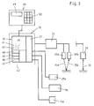
- Fig. 3 is the sensor 34 accordingly with the beam path 35 in the form of dashed line indicated with arrows on both sides.
- the input-output unit 37 is connected in terms of circuit to a microprocessor 39, which is a computer part 40 with a computer circuit 41, a comparator circuit 42 and one Memory area 43 with a first memory 44, a second memory 45, a third memory 46 and a fourth memory 47. That is further Controller 38 electrically connected to a control panel 48, which with a Display unit 49 and a keyboard 50 is equipped.
- the operation of the sewing machine 1 is as follows:
- the sewing machine 1 turns on after being switched on of electricity and possibly also the provision of compressed air for any existing pneumatic actuators are in an operational state, in which the support plate 23 is free, that is, no part of the sewing material to be sewn yet Platen 23 is placed. Accordingly, the platen 23 of applied to the emitted beam path 35 of the sensor 34. This happens by driving the sensor 34, which means a predetermined number of Sound waves are emitted from the transmitter part 34a and then that from the platen 23 reflected sound waves received as an echo from the receiver part 34b become. During this process, the time interval between the Start of sound wave transmission and reception of the sound wave echo measured. The time interval is a distance a of the sensor 34 from the platen 23 proportional value, so that the distance a is measured and in is stored in the first memory 44. The process described above is constant repeated.
- the measurement is carried out in the same way the distance of the difference a-d1, from which the computer circuit 41 connects with the previously determined distance a can calculate the thickness d1, the Value is then stored in the second memory 45.
- determining the thickness d1 of the sewing material part 24 causes the control 38 to set control values of the motor 9 and the actuators 15 and 29, so that the sewing machine thus automatically set to the values corresponding to the sewing of the workpiece 24 is.
- the current thickness will be the same associated, preselected setting data activated in a in the memory area 43 stored table are included.
- an outgoing edge 52 of the sewing material 25 also arrives in the working area of the sensor 34, which then again as after the detection the leading edge 51 a corresponding setting of the motor 9 and the actuators 15 and 29 causes.
- the computer part 40 guides with the comparator circuit 42 continuously comparing the determined distances d1 and d2 with one distance D stored in the fourth memory 47 by a maximum value represents.
- the maximum value is by a dash-dotted line 53 illustrates.
Landscapes
- Engineering & Computer Science (AREA)
- Textile Engineering (AREA)
- Mechanical Engineering (AREA)
- Environmental & Geological Engineering (AREA)
- Life Sciences & Earth Sciences (AREA)
- Ecology (AREA)
- Atmospheric Sciences (AREA)
- Biodiversity & Conservation Biology (AREA)
- Physics & Mathematics (AREA)
- Environmental Sciences (AREA)
- Hydrology & Water Resources (AREA)
- General Physics & Mathematics (AREA)
- Computer Hardware Design (AREA)
- Microelectronics & Electronic Packaging (AREA)
- Sewing Machines And Sewing (AREA)
- Length Measuring Devices With Unspecified Measuring Means (AREA)
Abstract
Description
- Fig. 1
- eine Ansicht auf den Kopf einer Nähmaschine,
- Fig. 2
- eine Vorderansicht der Nähmaschine in verkleinertem Maßstab entsprechend dem Sichtpfeil II in Fig. 1 und
- Fig. 3
- schematische Darstellung eines Teils der Steuerung für die Nähmaschine.
- 1
- Nähmaschine
- 2
- Grundplatte
- 3
- Ständer
- 4
- Arm
- 5
- Kopf
- 6
- Armwelle
- 7
- Handrad
- 8
- Riementrieb
- 9
- Antriebsmotor
- 10
- Nadelstange
- 11
- Nähnadel
- 12
- Fadenhebel
- 13
- Ende
- 14
- Öffnung
- 15
- Fadenspannvorrichtung
- 16
- Öse
- 17
- Öse
- 18
- Faden
- 19
- Stichplatte
- 20
- Stichloch
- 21
- Stichbildestelle
- 22
- Stoffschieber
- 23
- Auflageplatte
- 24
- 1. Nähgutteil
- 25
- 2. Nähgutteil
- 26
- Drückerfuß
- 27
- Drückerfuß
- 28
- Stoffdrückereinrichtung
- 29
- Stellglied
- 30
- Vorschubeinrichtung
- 31
- Vorschubrichtung
- 32
- Fläche
- 33
- Haltearm
- 34
- Sensor
- 34a Sender-Teil
- 34b Empfänger-Teil
- 35
- Strahlengang
- 36
- Schaltung
- 37
- Eingangs-Ausgangs-Einheit
- 38
- Steuerung
- 39
- Mikroprozessor
- 40
- Rechnerteil
- 41
- Rechner-Schaltkreis
- 42
- Vergleicher-Schaltung
- 43
- Speicherbereich
- 44
- 1. Speicher
- 45
- 2. Speicher
- 46
- 3. Speicher
- 47
- 4. Speicher
- 48
- Bedienfeld
- 49
- Anzeige-Einheit
- 50
- Tastatur
- 51
- einlaufende Kante
- 52
- auslaufende Kante
- 53
- Linie
- d1, d2, D
- Dicke
- a, e
- Abstand
- b Breite
- c Hub
Claims (5)
- Nähmaschine mit einem Sensor zur Erfassung der Nähgut-Dicke, mit folgenden Merkmalen:a) eine Grundplatte (2) mit einer Auflageplatte (23) für ein Nähgutteil (24;24,25)b) an der Auflageplatte (23) ist ein Ständer (3) mit einem sich daran anschließenden Arm (4) einschließlich einem Kopf (5) ausgebildet,c) eine Stichbildestelle (21) mit einer Nähnadel (11),d) eine Vorschubeinrichtung (30) zum Vorschieben des Nähguts (24;24,25) in einer Vorschubrichtung (31),e) der Sensor (34) mit einer Schaltung (36) zur Abgabe eines der Dicke (d1; d2) des Nähguts (24;24,25) vor der Stichbildestelle (21) entsprechenden Messwertes an eine elektrische Steuerung (3 8),f) die Steuerung (38) mit einer Einheit (37) zur Abgabe von Schaltbefehlen in Abhängigkeit der erfassten Dicke (d1,d2) an wenigstens ein Stellglied (15,29) und/oder einen Antriebsmotor (9) an der Nähmaschine (1),
dadurch gekennzeichnet:g) der Sensor ist als Ultraschall-Sensor (34) ausgebildet, der einen Sender-Teil (34a) und einen Empfänger-Teil (34b) aufweist,h) der Sender-Teil (34a) und der Empfänger-Teil (34b) sind in der Vorschubrichtung (31) vor der Stichbildestelle (21) und in einem Abstand (a) von der Auflageplatte (23) oberhalb dieser an dem Kopf (5) der Nähmaschine (1) angeordnet. - Nähmaschine nach Anspruch 1, dadurch gekennzeichnet, dass der SenderTeil (34a) und der Empfänger-Teil (34b) in einem Gehäuse angeordnet sind.
- Nähmaschine nach Anspruch 1 oder 2, gekennzeichnet durch die Merkmale:die Steuerung (38) mit einem ersten Speicher (44) zur Aufnahme eines den Abstand (a) zwischen dem Sensor (34) und der Auflageplatte (23) der Nähmaschine (1) repräsentierenden Wertes,die Steuerung (38) mit einem zweiten Speicher (45) zur Aufnahme eines die Dicke (d1) des Nähguts (24) repräsentierenden zweiten Wertes.
- Nähmaschine nach Anspruch 3, gekennzeichnet durch die Merkmale:die Steuerung (38) mit einem dritten Speicher (46) zur Aufnahme eines die sich aus dem ersten (24) und einem zweiten Nähgutteil (25) ergebenden Dicke (d2) repräsentierenden dritten Wertes.
- Nähmaschine nach einem der vorangehenden Ansprüche 3 oder 4, gekennzeichnet durch die Merkmale:die Steuerung (38) mit einem vierten Speicher (47) zur Aufnahme eines Maximalwertes der Dicke (D) als einen vierten Wert,die Steuerung (38) mit einer Vergleicher-Schaltung (42) zur Ermittlung der Differenz zwischen dem vierten Wert (Dicke D) und dem zweiten Wert (Dicke d1) oder dem dritten Wert (Dicke d2) und Verhinderung der Auslösung einer Schaltfunktion, wenn die Differenz kleiner gleich Null ist.
Priority Applications (1)
| Application Number | Priority Date | Filing Date | Title |
|---|---|---|---|
| SI200430220T SI1479809T1 (sl) | 2003-05-22 | 2004-04-20 | Šivalni stroj s senzorjem za merjenje debeline materiala za šivanje |
Applications Claiming Priority (2)
| Application Number | Priority Date | Filing Date | Title |
|---|---|---|---|
| DE10323158 | 2003-05-22 | ||
| DE10323158A DE10323158B3 (de) | 2003-05-22 | 2003-05-22 | Nähmaschine mit einem Sensor zur Erfassung der Nähgut-Dicke |
Publications (2)
| Publication Number | Publication Date |
|---|---|
| EP1479809A1 true EP1479809A1 (de) | 2004-11-24 |
| EP1479809B1 EP1479809B1 (de) | 2006-12-13 |
Family
ID=32478266
Family Applications (1)
| Application Number | Title | Priority Date | Filing Date |
|---|---|---|---|
| EP04009251A Expired - Lifetime EP1479809B1 (de) | 2003-05-22 | 2004-04-20 | Nähmaschine mit einem Sensor zur Erfassung der Nähgut-Dicke |
Country Status (9)
| Country | Link |
|---|---|
| EP (1) | EP1479809B1 (de) |
| JP (1) | JP2004344653A (de) |
| KR (1) | KR20040101020A (de) |
| CN (1) | CN1572946B (de) |
| AT (1) | ATE348211T1 (de) |
| DE (2) | DE10323158B3 (de) |
| PT (1) | PT1479809E (de) |
| SI (1) | SI1479809T1 (de) |
| TW (1) | TWM259800U (de) |
Cited By (3)
| Publication number | Priority date | Publication date | Assignee | Title |
|---|---|---|---|---|
| DE102005049771A1 (de) * | 2005-10-18 | 2007-04-19 | Dürkopp Adler AG | Nähmaschine |
| CN107764176A (zh) * | 2016-08-17 | 2018-03-06 | 北京大豪科技股份有限公司 | 针高检测装置和刺绣机 |
| CN115897079A (zh) * | 2022-10-29 | 2023-04-04 | 上海瑞仓电子科技有限公司 | 一种缝纫机布料厚薄检测方法 |
Families Citing this family (20)
| Publication number | Priority date | Publication date | Assignee | Title |
|---|---|---|---|---|
| DE102005029955A1 (de) * | 2005-06-28 | 2007-01-04 | Dürkopp Adler AG | Nähmaschine |
| JP5410723B2 (ja) * | 2008-09-30 | 2014-02-05 | Juki株式会社 | ミシン |
| CN101429712B (zh) * | 2008-12-09 | 2012-06-27 | 上海富山精密机械科技有限公司 | 一种工业缝纫机用光电控制系统 |
| US8511243B2 (en) * | 2010-03-31 | 2013-08-20 | Lear Corporation | Sewing machine and a method of operation |
| CN103866496B (zh) * | 2014-03-31 | 2016-05-25 | 杰克缝纫机股份有限公司 | 缝纫机用缝料检测装置及压脚高度自动调节系统 |
| JP2016064096A (ja) * | 2014-09-26 | 2016-04-28 | ブラザー工業株式会社 | ミシンとミシンの制御方法 |
| JP6552233B2 (ja) * | 2015-03-20 | 2019-07-31 | 蛇の目ミシン工業株式会社 | ミシン |
| CN105386251A (zh) * | 2015-12-11 | 2016-03-09 | 杰克缝纫机股份有限公司 | 一种缝料自动感应系统及方法 |
| CN106595461A (zh) * | 2016-12-02 | 2017-04-26 | 西安标准工业股份有限公司 | 一种防油防尘防震的缝料厚度检测系统及其检测方法 |
| CN108442044B (zh) * | 2018-04-25 | 2024-03-01 | 标准缝纫机菀坪机械有限公司 | 一种缝纫机缝料过坎自动感应装置和应用其的缝纫机 |
| KR102029590B1 (ko) * | 2018-06-25 | 2019-10-08 | 서호성 | 재봉기의 재봉물 두께 감지 장치 |
| DE202018103728U1 (de) * | 2018-06-29 | 2019-10-09 | Vorwerk & Co. Interholding Gmbh | Nähmaschine für den häuslichen Gebrauch |
| CN109440308B (zh) * | 2018-10-30 | 2021-01-26 | 杰克缝纫机股份有限公司 | 一种缝纫机上压脚交替量的自动调节装置及其控制方法 |
| CN109371586B (zh) * | 2018-12-13 | 2021-06-04 | 杰克缝纫机股份有限公司 | 针对缝料薄厚自动调整收线的缝纫机及其调整收线方法 |
| JP7316062B2 (ja) * | 2019-02-28 | 2023-07-27 | Juki株式会社 | 段部検出装置及び段部検出方法 |
| JP7321641B2 (ja) * | 2019-04-05 | 2023-08-07 | 株式会社ジャノメ | 布押え上下駆動装置および該装置を備えるミシン |
| CN110616510B (zh) * | 2019-10-09 | 2021-06-25 | 浙江众邦机电科技有限公司 | 一种布料的缝制方法、装置、设备及介质 |
| KR102122400B1 (ko) * | 2019-11-05 | 2020-06-15 | (주)썬테크 | 재봉기 및 원단 측정 모듈 |
| DE202021101337U1 (de) | 2021-03-16 | 2022-06-20 | Dürkopp Adler GmbH | Nähmaschine sowie Nachrüst-Bausatz für eine Nähmaschine |
| WO2025222138A1 (en) * | 2024-04-19 | 2025-10-23 | Inteva Products, Llc | Sewing head |
Citations (4)
| Publication number | Priority date | Publication date | Assignee | Title |
|---|---|---|---|---|
| US4574719A (en) * | 1983-06-28 | 1986-03-11 | Durkoppwerke Gmbh | Optoelectronic scanner for sewing machine |
| US4696246A (en) * | 1985-06-01 | 1987-09-29 | Frankl & Kirchner Gmbh | Device for detecting an overlapping edge of material on a sewing machine |
| US4829194A (en) * | 1985-06-03 | 1989-05-09 | Prouvost S.A. | Device for detecting the variation of thickness of a fabric and a process for calibrating same |
| EP0997567A1 (de) * | 1998-10-30 | 2000-05-03 | Johannes Sahl | Nähmaschinezubehör |
Family Cites Families (5)
| Publication number | Priority date | Publication date | Assignee | Title |
|---|---|---|---|---|
| CS248989B1 (en) * | 1984-08-06 | 1987-03-12 | Jozef Kunc | Device for electro-spark machining of rotating workpieces with larger diameter |
| JPS62277993A (ja) * | 1986-05-26 | 1987-12-02 | ジューキ株式会社 | ミシンの布端検知装置 |
| SE464766B (sv) * | 1988-03-21 | 1991-06-10 | Husqvarna Ab | Symaskin med laeges/roerelseavkaennare |
| US4928611A (en) * | 1988-11-15 | 1990-05-29 | Brother Kogyo Kabushiki Kaisha | Sewing machine with guide and ironing means for folding back and pressing stitched fabric margins |
| CN2310308Y (zh) * | 1997-09-03 | 1999-03-10 | 黄文俊 | 超声波测厚探头 |
-
2003
- 2003-05-22 DE DE10323158A patent/DE10323158B3/de not_active Expired - Fee Related
-
2004
- 2004-04-20 EP EP04009251A patent/EP1479809B1/de not_active Expired - Lifetime
- 2004-04-20 PT PT04009251T patent/PT1479809E/pt unknown
- 2004-04-20 AT AT04009251T patent/ATE348211T1/de not_active IP Right Cessation
- 2004-04-20 DE DE502004002263T patent/DE502004002263D1/de not_active Expired - Lifetime
- 2004-04-20 SI SI200430220T patent/SI1479809T1/sl unknown
- 2004-04-26 TW TW093206403U patent/TWM259800U/zh not_active IP Right Cessation
- 2004-05-17 JP JP2004146250A patent/JP2004344653A/ja active Pending
- 2004-05-18 CN CN2004100424128A patent/CN1572946B/zh not_active Expired - Fee Related
- 2004-05-20 KR KR1020040035960A patent/KR20040101020A/ko not_active Ceased
Patent Citations (4)
| Publication number | Priority date | Publication date | Assignee | Title |
|---|---|---|---|---|
| US4574719A (en) * | 1983-06-28 | 1986-03-11 | Durkoppwerke Gmbh | Optoelectronic scanner for sewing machine |
| US4696246A (en) * | 1985-06-01 | 1987-09-29 | Frankl & Kirchner Gmbh | Device for detecting an overlapping edge of material on a sewing machine |
| US4829194A (en) * | 1985-06-03 | 1989-05-09 | Prouvost S.A. | Device for detecting the variation of thickness of a fabric and a process for calibrating same |
| EP0997567A1 (de) * | 1998-10-30 | 2000-05-03 | Johannes Sahl | Nähmaschinezubehör |
Cited By (3)
| Publication number | Priority date | Publication date | Assignee | Title |
|---|---|---|---|---|
| DE102005049771A1 (de) * | 2005-10-18 | 2007-04-19 | Dürkopp Adler AG | Nähmaschine |
| CN107764176A (zh) * | 2016-08-17 | 2018-03-06 | 北京大豪科技股份有限公司 | 针高检测装置和刺绣机 |
| CN115897079A (zh) * | 2022-10-29 | 2023-04-04 | 上海瑞仓电子科技有限公司 | 一种缝纫机布料厚薄检测方法 |
Also Published As
| Publication number | Publication date |
|---|---|
| EP1479809B1 (de) | 2006-12-13 |
| CN1572946A (zh) | 2005-02-02 |
| DE10323158B3 (de) | 2004-07-08 |
| PT1479809E (pt) | 2007-02-28 |
| DE502004002263D1 (de) | 2007-01-25 |
| ATE348211T1 (de) | 2007-01-15 |
| KR20040101020A (ko) | 2004-12-02 |
| JP2004344653A (ja) | 2004-12-09 |
| CN1572946B (zh) | 2010-12-29 |
| SI1479809T1 (sl) | 2007-06-30 |
| TWM259800U (en) | 2005-03-21 |
Similar Documents
| Publication | Publication Date | Title |
|---|---|---|
| EP1479809B1 (de) | Nähmaschine mit einem Sensor zur Erfassung der Nähgut-Dicke | |
| DE3216993C2 (de) | Nähmaschine mit einer Einrichtung zum Herstellen von Formnähten | |
| CH697501B1 (de) | Vorrichtung und Verfahren zum Erfassen und Verarbeiten von Messgrössen bei einer Nähmaschine. | |
| DE2942166C2 (de) | Vorrichtung zum fortlaufenden Erfassen der Dicke elastischen Nähgutes | |
| DE3743281C2 (de) | ||
| DE102023120676A1 (de) | Abkettelfadenschneidvorrichtung | |
| DE2919681C2 (de) | Zwei- oder Mehrnadelnähmaschine | |
| DE3324715C2 (de) | ||
| DE3018797A1 (de) | Naehmaschine mit einer stichzaehler-korrekturvorrichtung | |
| DE102005012186B4 (de) | Fadenzufuhr bei einer Nähmaschine | |
| DE3912275C2 (de) | Nähmaschine | |
| DE3814440A1 (de) | Naehmaschine | |
| DE112017008004B4 (de) | Nähmaschine | |
| DE8333709U1 (de) | Nähmaschine mit einstellbarem Nadel -und Untertransport und einer Einrichtung zum Ansteuern eines vorbestimmbaren Endpunktes einer Naht | |
| DE3910870C2 (de) | ||
| DE3627470A1 (de) | Verfahren zum naehen der ecke einer doppelnaht mit einer zweinadelnaehmaschine | |
| EP1460160B1 (de) | Nähmaschine | |
| DE3617204C1 (de) | Vorrichtung zum Herstellen von an vorbestimmter Stelle endenden Naehten | |
| DE4233799A1 (de) | Hauptpresser-antriebsapparat fuer eine automatische einfassnaehmaschine | |
| DE3804920A1 (de) | Vorrichtung zur beendigung des letzten stiches an einer vorbestimmten stelle | |
| DE3519849C1 (de) | Blindstichnaehmaschine | |
| EP4060106B1 (de) | Nähmaschine | |
| DE102007041084A1 (de) | Einfassmaschine | |
| DE102005012188B4 (de) | Steuerung einer Fadenzufuhr einer Nähmaschine | |
| DD287545C4 (de) | Blindstichnaehmaschine |
Legal Events
| Date | Code | Title | Description |
|---|---|---|---|
| PUAI | Public reference made under article 153(3) epc to a published international application that has entered the european phase |
Free format text: ORIGINAL CODE: 0009012 |
|
| AK | Designated contracting states |
Kind code of ref document: A1 Designated state(s): AT BE BG CH CY CZ DE DK EE ES FI FR GB GR HU IE IT LI LU MC NL PL PT RO SE SI SK TR |
|
| AX | Request for extension of the european patent |
Extension state: AL HR LT LV MK |
|
| 17P | Request for examination filed |
Effective date: 20041117 |
|
| AKX | Designation fees paid |
Designated state(s): AT BE BG CH CY CZ DE DK EE ES FI FR GB GR HU IE IT LI LU MC NL PL PT RO SE SI SK TR |
|
| GRAP | Despatch of communication of intention to grant a patent |
Free format text: ORIGINAL CODE: EPIDOSNIGR1 |
|
| GRAS | Grant fee paid |
Free format text: ORIGINAL CODE: EPIDOSNIGR3 |
|
| GRAA | (expected) grant |
Free format text: ORIGINAL CODE: 0009210 |
|
| AK | Designated contracting states |
Kind code of ref document: B1 Designated state(s): AT BE BG CH CY CZ DE DK EE ES FI FR GB GR HU IE IT LI LU MC NL PL PT RO SE SI SK TR |
|
| PG25 | Lapsed in a contracting state [announced via postgrant information from national office to epo] |
Ref country code: DK Free format text: LAPSE BECAUSE OF FAILURE TO SUBMIT A TRANSLATION OF THE DESCRIPTION OR TO PAY THE FEE WITHIN THE PRESCRIBED TIME-LIMIT Effective date: 20061213 Ref country code: PL Free format text: LAPSE BECAUSE OF FAILURE TO SUBMIT A TRANSLATION OF THE DESCRIPTION OR TO PAY THE FEE WITHIN THE PRESCRIBED TIME-LIMIT Effective date: 20061213 Ref country code: FI Free format text: LAPSE BECAUSE OF FAILURE TO SUBMIT A TRANSLATION OF THE DESCRIPTION OR TO PAY THE FEE WITHIN THE PRESCRIBED TIME-LIMIT Effective date: 20061213 Ref country code: NL Free format text: LAPSE BECAUSE OF FAILURE TO SUBMIT A TRANSLATION OF THE DESCRIPTION OR TO PAY THE FEE WITHIN THE PRESCRIBED TIME-LIMIT Effective date: 20061213 Ref country code: IE Free format text: LAPSE BECAUSE OF FAILURE TO SUBMIT A TRANSLATION OF THE DESCRIPTION OR TO PAY THE FEE WITHIN THE PRESCRIBED TIME-LIMIT Effective date: 20061213 |
|
| REG | Reference to a national code |
Ref country code: GB Ref legal event code: FG4D Free format text: NOT ENGLISH |
|
| REG | Reference to a national code |
Ref country code: CH Ref legal event code: EP |
|
| REG | Reference to a national code |
Ref country code: IE Ref legal event code: FG4D Free format text: LANGUAGE OF EP DOCUMENT: GERMAN |
|
| REF | Corresponds to: |
Ref document number: 502004002263 Country of ref document: DE Date of ref document: 20070125 Kind code of ref document: P |
|
| REG | Reference to a national code |
Ref country code: PT Ref legal event code: SC4A Free format text: AVAILABILITY OF NATIONAL TRANSLATION Effective date: 20070116 |
|
| REG | Reference to a national code |
Ref country code: RO Ref legal event code: EPE |
|
| PG25 | Lapsed in a contracting state [announced via postgrant information from national office to epo] |
Ref country code: BG Free format text: LAPSE BECAUSE OF FAILURE TO SUBMIT A TRANSLATION OF THE DESCRIPTION OR TO PAY THE FEE WITHIN THE PRESCRIBED TIME-LIMIT Effective date: 20070313 Ref country code: SE Free format text: LAPSE BECAUSE OF FAILURE TO SUBMIT A TRANSLATION OF THE DESCRIPTION OR TO PAY THE FEE WITHIN THE PRESCRIBED TIME-LIMIT Effective date: 20070313 |
|
| PG25 | Lapsed in a contracting state [announced via postgrant information from national office to epo] |
Ref country code: ES Free format text: LAPSE BECAUSE OF FAILURE TO SUBMIT A TRANSLATION OF THE DESCRIPTION OR TO PAY THE FEE WITHIN THE PRESCRIBED TIME-LIMIT Effective date: 20070324 |
|
| ET | Fr: translation filed | ||
| NLV1 | Nl: lapsed or annulled due to failure to fulfill the requirements of art. 29p and 29m of the patents act | ||
| GBV | Gb: ep patent (uk) treated as always having been void in accordance with gb section 77(7)/1977 [no translation filed] |
Effective date: 20061213 |
|
| PLBE | No opposition filed within time limit |
Free format text: ORIGINAL CODE: 0009261 |
|
| STAA | Information on the status of an ep patent application or granted ep patent |
Free format text: STATUS: NO OPPOSITION FILED WITHIN TIME LIMIT |
|
| 26N | No opposition filed |
Effective date: 20070914 |
|
| PG25 | Lapsed in a contracting state [announced via postgrant information from national office to epo] |
Ref country code: GB Free format text: LAPSE BECAUSE OF FAILURE TO SUBMIT A TRANSLATION OF THE DESCRIPTION OR TO PAY THE FEE WITHIN THE PRESCRIBED TIME-LIMIT Effective date: 20061213 |
|
| BERE | Be: lapsed |
Owner name: DURKOPP ADLER A.G. Effective date: 20070430 |
|
| PG25 | Lapsed in a contracting state [announced via postgrant information from national office to epo] |
Ref country code: BE Free format text: LAPSE BECAUSE OF NON-PAYMENT OF DUE FEES Effective date: 20070430 |
|
| PG25 | Lapsed in a contracting state [announced via postgrant information from national office to epo] |
Ref country code: GR Free format text: LAPSE BECAUSE OF FAILURE TO SUBMIT A TRANSLATION OF THE DESCRIPTION OR TO PAY THE FEE WITHIN THE PRESCRIBED TIME-LIMIT Effective date: 20070314 |
|
| PG25 | Lapsed in a contracting state [announced via postgrant information from national office to epo] |
Ref country code: AT Free format text: LAPSE BECAUSE OF NON-PAYMENT OF DUE FEES Effective date: 20070420 |
|
| REG | Reference to a national code |
Ref country code: CH Ref legal event code: PL |
|
| PG25 | Lapsed in a contracting state [announced via postgrant information from national office to epo] |
Ref country code: CH Free format text: LAPSE BECAUSE OF NON-PAYMENT OF DUE FEES Effective date: 20080430 Ref country code: EE Free format text: LAPSE BECAUSE OF FAILURE TO SUBMIT A TRANSLATION OF THE DESCRIPTION OR TO PAY THE FEE WITHIN THE PRESCRIBED TIME-LIMIT Effective date: 20061213 Ref country code: LI Free format text: LAPSE BECAUSE OF NON-PAYMENT OF DUE FEES Effective date: 20080430 |
|
| PG25 | Lapsed in a contracting state [announced via postgrant information from national office to epo] |
Ref country code: MC Free format text: LAPSE BECAUSE OF NON-PAYMENT OF DUE FEES Effective date: 20070430 |
|
| PG25 | Lapsed in a contracting state [announced via postgrant information from national office to epo] |
Ref country code: CY Free format text: LAPSE BECAUSE OF FAILURE TO SUBMIT A TRANSLATION OF THE DESCRIPTION OR TO PAY THE FEE WITHIN THE PRESCRIBED TIME-LIMIT Effective date: 20061213 Ref country code: LU Free format text: LAPSE BECAUSE OF NON-PAYMENT OF DUE FEES Effective date: 20070420 |
|
| PG25 | Lapsed in a contracting state [announced via postgrant information from national office to epo] |
Ref country code: HU Free format text: LAPSE BECAUSE OF FAILURE TO SUBMIT A TRANSLATION OF THE DESCRIPTION OR TO PAY THE FEE WITHIN THE PRESCRIBED TIME-LIMIT Effective date: 20070614 |
|
| PGFP | Annual fee paid to national office [announced via postgrant information from national office to epo] |
Ref country code: FR Payment date: 20100506 Year of fee payment: 7 Ref country code: PT Payment date: 20100408 Year of fee payment: 7 |
|
| PGFP | Annual fee paid to national office [announced via postgrant information from national office to epo] |
Ref country code: IT Payment date: 20100429 Year of fee payment: 7 Ref country code: SI Payment date: 20100408 Year of fee payment: 7 Ref country code: SK Payment date: 20100413 Year of fee payment: 7 |
|
| REG | Reference to a national code |
Ref country code: PT Ref legal event code: MM4A Free format text: LAPSE DUE TO NON-PAYMENT OF FEES Effective date: 20111020 |
|
| REG | Reference to a national code |
Ref country code: SI Ref legal event code: KO00 Effective date: 20111123 |
|
| REG | Reference to a national code |
Ref country code: SK Ref legal event code: MM4A Ref document number: E 1671 Country of ref document: SK Effective date: 20110420 |
|
| REG | Reference to a national code |
Ref country code: FR Ref legal event code: ST Effective date: 20111230 |
|
| PG25 | Lapsed in a contracting state [announced via postgrant information from national office to epo] |
Ref country code: FR Free format text: LAPSE BECAUSE OF NON-PAYMENT OF DUE FEES Effective date: 20110502 Ref country code: PT Free format text: LAPSE BECAUSE OF NON-PAYMENT OF DUE FEES Effective date: 20111020 |
|
| PG25 | Lapsed in a contracting state [announced via postgrant information from national office to epo] |
Ref country code: IT Free format text: LAPSE BECAUSE OF NON-PAYMENT OF DUE FEES Effective date: 20110420 Ref country code: SI Free format text: LAPSE BECAUSE OF NON-PAYMENT OF DUE FEES Effective date: 20110421 Ref country code: SK Free format text: LAPSE BECAUSE OF NON-PAYMENT OF DUE FEES Effective date: 20110420 |
|
| PGFP | Annual fee paid to national office [announced via postgrant information from national office to epo] |
Ref country code: RO Payment date: 20220408 Year of fee payment: 19 Ref country code: DE Payment date: 20220525 Year of fee payment: 19 Ref country code: CZ Payment date: 20220414 Year of fee payment: 19 |
|
| PGFP | Annual fee paid to national office [announced via postgrant information from national office to epo] |
Ref country code: TR Payment date: 20220413 Year of fee payment: 19 |
|
| P01 | Opt-out of the competence of the unified patent court (upc) registered |
Effective date: 20230510 |
|
| REG | Reference to a national code |
Ref country code: DE Ref legal event code: R119 Ref document number: 502004002263 Country of ref document: DE |
|
| PG25 | Lapsed in a contracting state [announced via postgrant information from national office to epo] |
Ref country code: RO Free format text: LAPSE BECAUSE OF NON-PAYMENT OF DUE FEES Effective date: 20230420 Ref country code: DE Free format text: LAPSE BECAUSE OF NON-PAYMENT OF DUE FEES Effective date: 20231103 Ref country code: CZ Free format text: LAPSE BECAUSE OF NON-PAYMENT OF DUE FEES Effective date: 20230420 |