EP1480316A2 - Stator of two rotor single stator type electric motor - Google Patents
Stator of two rotor single stator type electric motor Download PDFInfo
- Publication number
- EP1480316A2 EP1480316A2 EP04011101A EP04011101A EP1480316A2 EP 1480316 A2 EP1480316 A2 EP 1480316A2 EP 04011101 A EP04011101 A EP 04011101A EP 04011101 A EP04011101 A EP 04011101A EP 1480316 A2 EP1480316 A2 EP 1480316A2
- Authority
- EP
- European Patent Office
- Prior art keywords
- stator
- common axis
- elongate plate
- rotor
- bolts
- Prior art date
- Legal status (The legal status is an assumption and is not a legal conclusion. Google has not performed a legal analysis and makes no representation as to the accuracy of the status listed.)
- Withdrawn
Links
- 239000002991 molded plastic Substances 0.000 claims abstract description 24
- 229910000831 Steel Inorganic materials 0.000 claims abstract description 22
- 239000010959 steel Substances 0.000 claims abstract description 22
- 239000000696 magnetic material Substances 0.000 claims abstract description 10
- 150000001875 compounds Chemical class 0.000 claims description 10
- 239000000843 powder Substances 0.000 claims description 7
- 229910052751 metal Inorganic materials 0.000 claims description 4
- 239000002184 metal Substances 0.000 claims description 4
- 230000004907 flux Effects 0.000 description 6
- XEEYBQQBJWHFJM-UHFFFAOYSA-N Iron Chemical compound [Fe] XEEYBQQBJWHFJM-UHFFFAOYSA-N 0.000 description 4
- 230000005540 biological transmission Effects 0.000 description 4
- 238000004519 manufacturing process Methods 0.000 description 3
- 230000007246 mechanism Effects 0.000 description 3
- 230000008901 benefit Effects 0.000 description 2
- 238000010276 construction Methods 0.000 description 2
- 229910052742 iron Inorganic materials 0.000 description 2
- 229910052782 aluminium Inorganic materials 0.000 description 1
- XAGFODPZIPBFFR-UHFFFAOYSA-N aluminium Chemical compound [Al] XAGFODPZIPBFFR-UHFFFAOYSA-N 0.000 description 1
- 238000002485 combustion reaction Methods 0.000 description 1
- 239000002826 coolant Substances 0.000 description 1
- 238000001746 injection moulding Methods 0.000 description 1
- 230000004048 modification Effects 0.000 description 1
- 238000012986 modification Methods 0.000 description 1
- 239000007787 solid Substances 0.000 description 1
- 229910001220 stainless steel Inorganic materials 0.000 description 1
- 239000010935 stainless steel Substances 0.000 description 1
Images




Classifications
-
- H—ELECTRICITY
- H02—GENERATION; CONVERSION OR DISTRIBUTION OF ELECTRIC POWER
- H02K—DYNAMO-ELECTRIC MACHINES
- H02K1/00—Details of the magnetic circuit
- H02K1/06—Details of the magnetic circuit characterised by the shape, form or construction
- H02K1/08—Salient poles
-
- H—ELECTRICITY
- H02—GENERATION; CONVERSION OR DISTRIBUTION OF ELECTRIC POWER
- H02K—DYNAMO-ELECTRIC MACHINES
- H02K1/00—Details of the magnetic circuit
- H02K1/06—Details of the magnetic circuit characterised by the shape, form or construction
- H02K1/12—Stationary parts of the magnetic circuit
- H02K1/14—Stator cores with salient poles
-
- H—ELECTRICITY
- H02—GENERATION; CONVERSION OR DISTRIBUTION OF ELECTRIC POWER
- H02K—DYNAMO-ELECTRIC MACHINES
- H02K1/00—Details of the magnetic circuit
- H02K1/06—Details of the magnetic circuit characterised by the shape, form or construction
- H02K1/12—Stationary parts of the magnetic circuit
- H02K1/18—Means for mounting or fastening magnetic stationary parts on to, or to, the stator structures
-
- H—ELECTRICITY
- H02—GENERATION; CONVERSION OR DISTRIBUTION OF ELECTRIC POWER
- H02K—DYNAMO-ELECTRIC MACHINES
- H02K16/00—Machines with more than one rotor or stator
- H02K16/02—Machines with one stator and two or more rotors
-
- H—ELECTRICITY
- H02—GENERATION; CONVERSION OR DISTRIBUTION OF ELECTRIC POWER
- H02K—DYNAMO-ELECTRIC MACHINES
- H02K3/00—Details of windings
- H02K3/04—Windings characterised by the conductor shape, form or construction, e.g. with bar conductors
- H02K3/24—Windings characterised by the conductor shape, form or construction, e.g. with bar conductors with channels or ducts for cooling medium between the conductors
Definitions
- the present invention relates in general to electric motors, and more particularly to electric motors of a two rotor single stator type which comprises outer and inner rotors which rotate around and within a common stator. More specifically, the present invention is concerned with a stator for the two rotor single stator type electric motor.
- the stator of the electric motor of the published application comprises a stator core that includes a plurality of stator teeth that are circumferentially arranged around a common axis of the motor at evenly spaced intervals.
- Each stator tooth has a generally rectangular parallelepiped shape and includes a plurality of pressed flat magnetic steel plates that are aligned along the common axis while intimately and closely contacting to one another.
- the stator core upon assembly, has a waterwheel shape having a plurality of vanes (viz., stator teeth) circumferentially arranged about an axis of the stator.
- Each stator tooth has a coil that is put therearound making round-trips in a direction parallel with the common axis.
- stator core thus assembled is sandwiched between two axially spaced supporting brackets and tightened by a plurality of bolts and nuts.
- Each bolt extends in a direction parallel with the common axis in and along a space defined between adjacent two of the stator teeth.
- the space is filled with a molded plastic.
- each stator tooth has at radially outer and inner ends thereof yoke portions that project in a circumferential direction. Due to provision of such yoke portions, an outward magnetic resistance (which will be referred to "magnetic bypass resistance” hereinafter) of each stator tooth is increased, and thus, undesired outward dispersal of the magnetic flux through the stator tooth is suppressed or at least minimized.
- magnetic bypass resistance which will be referred to "magnetic bypass resistance” hereinafter
- the space defined between adjacent two of the stator teeth is filled with a molded plastic through which the connecting bolts extend axially.
- One end of each bolt is connected to a motor housing, so that the stator is held by the motor housing in a so-called cantilever holding way.
- the bolts function to generate the magnetic bypass resistance.
- the magnetic bypass resistance is mainly generated by the yoke portions of each stator tooth and the bolts.
- Such measures for producing the magnetic bypass resistance brings about an increase in cost of the electric motor due to the complicated shape of the stator teeth and a time-consumed assembling work.
- a stator for use in a two rotor single stator type electric motor in which inner and outer rotors are rotated independently in and around the stator upon application of current to the stator, the stator comprising a stator core including a plurality of stator teeth that are circumferentially arranged around a common axis at evenly spaced intervals leaving a plurality of identical spaces each being defined between adjacent two of the stator teeth, each stator tooth including a plurality of flat magnetic steel plates that are aligned along the common axis while intimately and closely contacting to one another; a plurality of coils put around the stator teeth respectively; bolts that extend through the identical spaces of the stator core in a direction parallel with the common axis for combining the flat magnetic steel plates to have a fixed structure of the stator core; a molded plastic that fills the identical spaces of the stator core; and a plurality of elongate plate bars that extend in the identical spaces through the stator
- a stator for use in a two rotor single stator type electric motor in which inner and outer rotors are rotated independently in and around the stator upon application of a compound electric current to the stator, the stator comprising a stator core including a plurality of stator teeth that are circumferentially arranged around a common axis at evenly spaced intervals leaving a plurality of identical spaces each being defined between adjacent two of the stator teeth, each stator tooth including a plurality of flat magnetic steel plates that are aligned along the common axis while intimately and cioseiy contacting to one another; a plurality of coils put around the stator teeth respectively; two supporting brackets between which the stator teeth of the stator core are sandwiched; bolts and nuts that fasten the two supporting brackets to tightly and intimately connect the magnetic steel plates of each stator tooth to one another, the bolts extending through the identical spaces in parallel with the common axis; a molded stator core including a stator core, the stator teeth that
- a two rotor single stator type electric motor powered by a compound electric current which comprises a cylindrical stator that includes a stator core including a plurality of stator teeth that are circumferentially arranged around a common axis at evenly spaced intervals leaving a plurality of identical spaces each being defined between adjacent two of the stator teeth, each stator tooth including a plurality of flat magnetic steel plates that are aligned along the common axis while intimately and closely contacting to one another; a plurality of coils put around the stator teeth respectively; bolts that extend through the identical spaces of the stator core in a direction parallel with the common axis for combining the flat magnetic steel plates to have a fixed structure of the stator core; a molded plastic that fills the identical spaces of the stator core; and a plurality of elongate plate bars that extend in the identical spaces through the molded plastic respectively, each elongate plate bar extending in parallel with the common axis and
- Fig. 1 there is shown a hybrid type drive unit HTDU for a wheeled motor vehicle, to which a two rotor single stator type electric motor is practically applied.
- the hybrid type drive unit HTDU comprises generally an engine (viz., internal combustion engine or the like) E, a two rotor single stator type electric motor M, a ravigneawx type planetary gear unit G and a drive output mechanism D.
- Engine E is a prime mover of the drive unit HTDU, which has an output shaft 20 that is connected to a second ring gear R2 of the planetary gear unit G through a rotation fluctuation absorbing damper 21 and a multiple disc dutch 22, as shown.
- Electric motor M is an auxiliary mover of the drive unit HTDU, which has two motor generator functions. As shown, electric motor M is installed in a space defined by both a motor cover 40 and a motor case 41 and is connected to motor case 41.
- Electric motor M comprises a cylindrical stator ST that has a plurality of coils disposed thereabout, a cylindrical inner rotor IR that is rotatably arranged in stator ST and has a plurality of permanent magnets disposed thereon, a cylindrical outer rotor OR that is rotatably arranged around stator ST and has a plurality of permanent magnets disposed thereon.
- stator ST, inner rotor IR and outer rotor OR are concentrically arranged to constitute a triple-layer cylindrical construction.
- a first shaft 23 that is hollow is coaxially connected to inner rotor IR to rotate therewith.
- This hollow first shaft 23 axially extends rightward to connect to a first sun gear S1 of planetary gear unit G.
- a second shaft 24 that is also hollow is connected through a torque transmission plate OR-1 to outer rotor OR to rotate therewith. This second shaft 24 extends rightward in the hollow first shaft 23 to connect to a second sun gear S2 of planetary gear unit G, as shown.
- Ravigneawx type planetary gear unit G is a continuously variable transmission mechanism that inputs a power or torque from at least one of engine E and electric motor E and continuously varies the rotation speed of an power outputted therefrom. As shown, planetary gear unit G is installed in a space defined by a front cover 42 and a gear housing 43.
- planetary gear unit G comprises a common carrier C that carries mutually meshed first and second pinions P1 and P2, the above-mentioned first sun gear S1 that is meshed with first pinions P1, the above-mentioned second sun gear S2 that is meshed with second pinions P2, a first ring gear R1 that is meshed with first pinions P1, and a second ring gear R2 that is meshed with second pinions P2.
- first ring gear R1 and gear housing 43 there is arranged a multi disc brake 25, and to the common carrier C, there is connected an output gear 26.
- Drive output mechanism D comprises the above-mentioned output gear 26, a first counter gear 27 that is meshed with output gear 26, a second counter gear 28 that is integral with first counter gear 27, a drive gear 29 that is meshed with second counter gear 28, a differential gear 30 that is meshed with drive gear 29 and drive shafts 31A and 31B that extend leftward and rightward from differential gear 30 respectively.
- a torque led to output gear 26 from planetary gear unit G is led through first counter gear 27, second counter gear 28, drive gear 29 and differential gear 30 to left and right drive shafts 31A and 31B thereby to move an associated motor vehicle through drive road wheels (not shown).
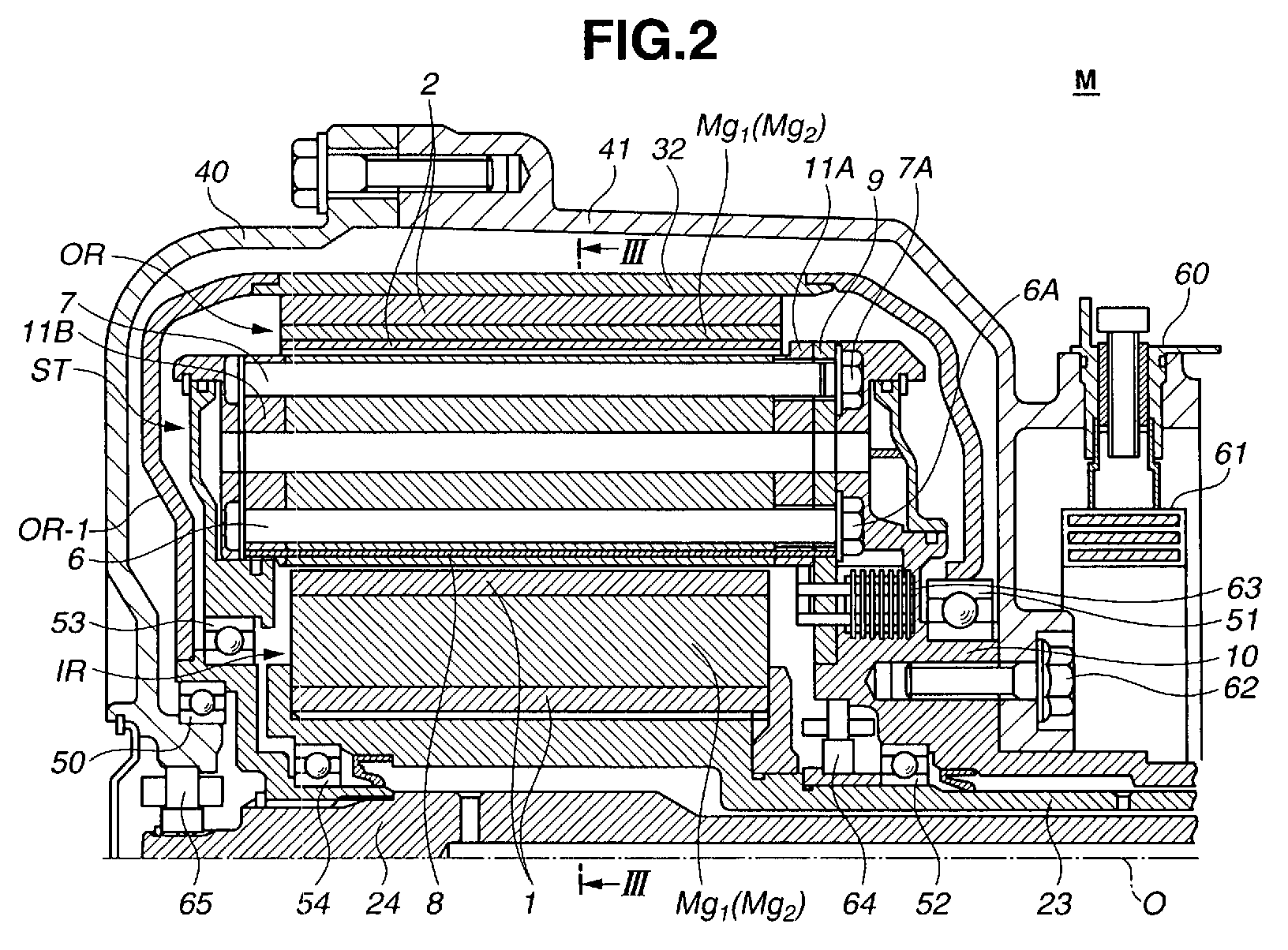
- FIG. 2 there is shown an enlarged sectional view of the two rotor single stator type electric motor M at a portion that is enclosed by a block as indicated by "X" in Fig. 1.
- a stator according to the present invention is practically applied to such electric motor M.
- inner rotor IR comprises a cylindrical rotor base 1 that is connected to first hollow shaft 23 and includes a plurality of pressed out flat magnetic steel plates aligned along a common axis O of electric motor M.
- inner rotor IR and first hollow shaft 23 rotate about the common axis O together like a single unit.
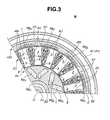
- Fig. 3 that is a sectional view taken along the line III-III of Fig. 2, in the rotor base 1, there are embedded twelve permanent magnets Mg1 and Mg2.
- twelve permanent magnets Mg1 and Mg2 As is understood from the drawing, six pairs of permanent magnets are arranged in the rotor base 1 at equally spaced intervals, each pair including two identical magnets Mg1 and Mg1 or two identical magnets Mg2 and Mg2. These two magnets Mg1 and Mg2 are different in polarity. More specifically, two identical magnets Mg1 and Mg1 (or Mg2 and Mg2) of each pair are arranged to face each other with their radially outer ends largely spaced.
- six polar pairs are provided in case of inner rotor IR.
- Outer rotor OR comprises a cylindrical rotor base 2 that is secured to an inner surface of a cylindrical shell 32. Cylindrical shell 32 is connected to second hollow shaft 24 through the above-mentioned torque transmission plate OR-1. As is seen from Fig. 2, torque transmission plate OR-1 is connected to second hollow shaft 24 through a spline connection. Thus, outer rotor OR and second hollow shaft 24 rotate about the common axis O together like a single unit.
- rotator base 2 of outer rotor OR includes a plurality of pressed out flat magnetic steel plates aligned along the common axis O of electric motor M.
- the twelve permanent magnets Mg1 and Mg2 which are alternatively arranged at equally spaced intervals.
- the twelve magnets Mg1 and Mg2 are alternately arranged at equally spaced intervals. That is, in case of outer rotor OR, one magnet Mg1 (or Mg2) is placed between two identical magnets Mg2 and Mg2 (or Mg1 and Mg1).
- three polar pairs are provided.
- outer rotor OR is rotatably held at its left and right portions by both motor cover 40 and motor case 41 through respective ball bearings 50 and 51.
- the left portion of outer rotor OR is rotatably held by stator ST through a ball bearing 53.
- Inner rotor IR is rotatably held at its left and right portions by both second hollow shaft 24 and motor case 41 through respective hall bearings 54 and 52.
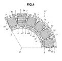
- cylindrical stator ST comprises a cylindrical stator core that includes a plurality (eighteen in the illustrated embodiment) of stator teeth 3 that are circumferentially arranged around the common axis O of motor M at evenly spaced intervals.
- Each stator tooth 3 has a generally T-shaped cross section and includes a plurality of pressed flat magnetic steel plates that are aligned along the common axis O while intimately and closely contacting to one another. That is, each stator tooth 3 has at a radially outer end thereof a yoke portion 3Y that projects in a circumferential direction, as shown.
- the stator core upon assembly, has a waterwheel shape having a plurality of vanes (viz., stator teeth 3) that are circumferentially arranged about the common axis O.
- each stator tooth 3 has a coil 4U, 4V or 4W put therearound making round-trips in a direction parallel with the common axis O.
- Inner and outer bolts 6 and 7 extend axially in radially inner and outer portions of molded plastic 5 of each space, respectively. These bolts 6 and 7 are constructed of a nonmagnetic metal, such as aluminum, stainless steel or the like.
- an elongate plate bar 8 constructed of a magnetic metal extends axially in molded plastic 5 through an area defined between inner bolt 6 and a radially inner surface of stator ST. That is, elongate plate bar 8 extends in parallel with the common axis O of electric motor M.
- elongate plate bar 8 has an electric resistance that is higher than that of the bolts 6 and 7.
- stator ST As is seen from Fig. 2, a right end portion of stator ST is fixed to motor case 41 through a right end plate 9 and a stator shaft 10.
- each coil 4U, 4V or 4W is put around the corresponding stator tooth 3 except yoke portion 3Y.
- stator core thus assembled in the above-mentioned manner is sandwiched between axially spaced two supporting brackets 11A and 11B and tightened by inner and outer bolts 6 and 7 and nuts 6A and 7A. If desired, in place of the bolts 6 and 7, rivet pins may be used for tightening the stator core.
- Each elongate magnetic plate bar 8 is a laminated magnetic metal bar that comprises a plurality of magnetic steel thin plates that are combined by an insulating member, such as an insulating tape or the like.
- each elongate magnetic plate bar 8 extends axially in molded plastic 5 through the area defined between inner bolt 6 and the radially inner surface of stator ST.
- each elongate plate bar 8 can be tightly set in the proper position of the molded plastic 5 between adjacent two of the stator teeth 3, as is understood from Fig. 3.
- each elongate plate bar 8 can have a sufficient durability against any stress applied to stator ST.
- the eighteen coils 4U, 4V and 4W of stator ST are parted into six groups each including three different coils 4U, 4V and 4W which are the coil 4U through which a U-phase current flows, the coil 4V through which a V-phase current flows and the coil 4W through which a W-phase current flows. That is, the six groups of coils 4U, 4V and 4W are arranged around common axis O of the motor M at equally spaced intervals with each group keeping the order of 4U, 4V and 4W, as shown.
- an inner rotor speed sensor is denoted by numeral 64, which senses the rotation speed of inner rotor IR
- an outer rotor speed sensor is denoted by numeral 65, which senses the rotation speed of outer rotor OR.
- the stator ST Upon feeding the compound electric current to the eighteen coils 4U, 4V and 4W, the stator ST produces both a rotating field for inner rotor IR and a rotating field for outer rotor OR and thus, inner and outer rotors IR and OR are rotated in and around the stator ST individually.
- the nature of the compound electric current is varied by information signals from the two speed sensors 64 and 65, so that each of the two rotors IR and OR can rotate at a desired speed.
- the elongate magnetic plate bars 8 each being positioned between adjacent two of the stator teeth 3 and near inner rotor IR, a desired magnetic bypass resistance is produced. Thus, even when alternation of the magnaflux takes place, a loss caused by eddy current can be reduced. It is to be noted that the laminated structure of the magnetic plate bars 8 exhibits a remarked work for reducing the loss. This advantage is not expected from the bolts 6 and 7 because these are of a solid structure.
- stator ST Because the elongate magnetic plate bars 8 are members separate from the stator core that includes stator teeth 3, provision of magnetic plate bars 8 to stator ST does not induce a complicated structure of stator ST. Thus, production of stator ST is easily achieved without increasing the cost of the same.
- the magnetic flux from magnets Mg1 and Mg2 of inner rotor IR can produce a corresponding number of magnetic paths by using magnets Mg1 and Mg2 of outer rotor OR through stator ST, and the magnetic flux from magnets Mg1 and Mg2 of outer rotor RO can not produce a corresponding number of magnetic paths by using magnets Mg1 and Mg2 of inner rotor IR through stator ST.
- elongate magnetic plate bars 8 around and near inner rotor IR, as is described hereinabove.
- the magnetic plate bars 8 function to assist the magnetic flux from the magnets Mg1 and Mg2 of outer rotor OR to produce the corresponding number of magnetic paths. Because of the above-mentioned reason, there is no need of providing stator ST with a special structure by which production of the needed number of magnetic paths for outer rotor OR is assisted. Thus, production of stators ST is easily achieved without increasing the cost of the same.
- FIG. 5 there is shown an electric motor M-2 that is equipped with a stator ST-2 of a second embodiment of the present invention.
- stator ST-2 of this second embodiment is substantially the same as stator ST of the above-mentioned first embodiment except that in the second embodiment, another elongate magnetic plate bar 8-2 is provided in the molded plastic 5 near outer rotor OR. That is, each magnetic plate bar 8-2 is placed between outer bolt 7 and a radially outer surface of stator ST-2.
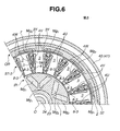
- FIG. 6 there is shown an electric motor M-3 that is equipped with a stator ST-3 of a third embodiment of the present invention.
- stator ST-3 of this third embodiment is substantially the same as stator ST of the above-mentioned first embodiment except that in the third embodiment, each elongate magnetic plate bar 8-3 has lateral edges that contact the two adjacent stator teeth 3. Because of a so-called bridge arrangement made by the magnetic plate bars 8-3, a mechanical strength of stator ST is increased, and because of the same reason, the magnetic plate bars 8-3 can be set in right positions in stator ST. Furthermore, due to the increased mechanical strength of stator ST, inner and outer bolts 6 and 7 can be reduced in size and weight, which brings about a reduced cost of stator ST.
- FIG. 7 there is shown an electric motor M-4 that is equipped with a stator ST-4 of a fourth embodiment of the present invention.
- stator ST-4 of this fourth embodiment is substantially the same as the above-mentioned stator ST-3 of the third embodiment except that in the fourth embodiment, each elongate magnetic plate bar 8-4 is a powder magnetic core.
- the powder magnetic core has an iron loss that is smaller than that of a magnetic steel plate, and thus, the iron loss that is inevitably produced when the rotors IR and OR are driven by a high frequency compound electric current can be reduced. Accordingly, performance of the electric motor M-4 is increased.
- the magnetic flux density provided by the powder magnetic core is small as compared with a magnetic steel plate.
- a certain size is needed by the powder magnetic core, which brings about an easiness with which the elongate magnetic plate bar 8-4 is produced from a powder magnetic material.
Landscapes
- Engineering & Computer Science (AREA)
- Power Engineering (AREA)
- Iron Core Of Rotating Electric Machines (AREA)
Abstract
Description
Claims (12)
- A stator (ST, ST-2, ST-3, ST-4) for use in a two rotor single stator type electric motor (M, M-2, M-3, M-4) in which inner and outer rotors (IN, OR) are rotated independently in and around the stator (ST, ST-2, ST-3, ST-4) upon application of current to the stator, the stator (ST, ST-2, ST-3, ST-4) comprising:a stator core including a plurality of stator teeth (3) that are circumferentially arranged around a common axis (O) at evenly spaced intervals leaving a plurality of identical spaces each being defined between adjacent two of the stator teeth (3), each stator tooth (3) including a plurality of flat magnetic steel plates that are aligned along the common axis (O) while intimately and closely contacting to one another;a plurality of coils (4U, 4V, 4W) put around the stator teeth (3) respectively;bolts (6, 7) that extend through the identical spaces of the stator core in a direction parallel with the common axis (O) for combining the flat magnetic steel plates to have a fixed structure of the stator core;a molded plastic (5) that fills the identical spaces of the stator core; anda plurality of elongate plate bars (8, 8-2, 8-3, 8-4) that extend in the identical spaces through the molded plastic (5) respectively, each elongate plate bar (8, 8-2, 8-3, 8-4) extending in parallel with the common axis (O) and being constructed of a magnetic material that has an electric resistance higher than the bolts (6,7).
- A stator as claimed in Claim 1, in which each of the elongate plate bars (8, 8-2, 8-3, 8-4) extends in the vicinity of at least one of the inner and outer rotors (IR, OR).
- A stator as claimed in Claim 1 or 2, in which each of the elongate plate bars (8, 8-2, 8-3, 8-4) is a laminated magnetic metal bar that comprises a plurality of magnetic steel thin plates that are combined by an insulating member.
- A stator as claimed in Claim 1, 2 or 3, further comprising other elongate plate bars (8-2) that are constructed of a magnetic material and extend in the identical spaces through the molded plastic (5) respectively, each of the other elongate plate bars (8-2) extending in parallel with the common axis (O) and constructed of a magnetic material that has an electric resistance higher than the bolts (6,7).
- A stator as claimed in Claim 1, 2, 3 or 4, in which each of the elongate plate bars (8, 8-3, 8-4) extends in the vicinity of a selected one (IR) of the inner and outer rotors (IR, OR), the selected one rotor (IR) having polar pairs of which number is smaller than those of the other rotor (OR).
- A stator as claimed in Claim 1, 2, 3, 4 or 5, in which each of the elongate plate bars (8-3, 8-4) has lateral edges that contact the adjacent two of the stator teeth (3) respectively.
- A stator as claimed in Claim 1, 2, 3, 4, 5 or 6, in which each of the elongate plate bars (8, 8-2, 8-3, 8-4) is a powder magnetic core.
- A stator as claimed in Claim 7, in which each of the elongate plate bars (8-4) has lateral edges that contact the adjacent two of the stator teeth respectively.
- A stator as claimed in Claim 1, 2, 3, 4, 5, 6, 7 or 8, in which each of the elongate plate bars (8, 8-3, 8-4) is placed between the bolt (6) and a radially inner surface of the stator (ST).
- A stator as claimed in Claim 1, 2, 3, 4, 5, 6, 7 or 8, in which each of the elongate plate bars (8-2) is placed between the bolt (7) and a radially outer surface of the stator (ST).
- A stator (ST, ST-2, ST-3, ST-4) for use in a two rotor single stator type electric motor (M, M-2, M-3, M-4) in which inner and outer rotors (IR, OR) are rotated independently in and around the stator (ST, ST-2, ST-3, ST-4) upon application of a compound electric current to the stator, the stator (ST, ST-2, ST-3, ST-4) comprising:a stator core including a plurality of stator teeth (3) that are circumferentially arranged around a common axis (O) at evenly spaced intervals leaving a plurality of identical spaces each being defined between adjacent two of the stator teeth (3), each stator tooth including a plurality of flat magnetic steel plates that are aligned along the common axis (O) while intimately and closely contacting to one another;a plurality of coils (4U, 4V, 4W) put around the stator teeth (3) respectively;two supporting brackets (11A, 11B) between which the stator teeth (3) of the stator core are sandwiched;bolts (6, 7) and nuts (6A, 7A) that fasten the two supporting brackets (11A, 11B) to tightly and intimately connect the magnetic steel plates of each stator tooth to one another, the bolts (6, 7) extending through the identical spaces in parallel with the common axis (O);a molded plastic (5) that fills the identical spaces of the stator core; anda plurality of elongate plate bars (8, 8-2, 8-3, 8-4) that extend in the identical spaces through the molded plastic (5) respectively, each elongate plate bar (8, 8-2, 8-3, 8-4) extending in parallel with the common axis (O) and being constructed of a magnetic material that has an electric resistance higher than the bolts (6, 7).
- A two rotor single stator type electric motor (M, M-2, M-3, M-4) powered by a compound electric current, comprising:a cylindrical stator (ST, ST-2, ST-3, ST-4) that includes a stator core including a plurality of stator teeth (3) that are circumferentially arranged around a common axis (O) at evenly spaced intervals leaving a plurality of identical spaces each being defined between adjacent two of the stator teeth (3), each stator tooth including a plurality of flat magnetic steel plates that are aligned along the common axis (0) while intimately and closely contacting to one another; a plurality of coils (4U, 4V, 4W) put around the stator teeth (3) respectively; bolts (6, 7) that extend through the identical spaces of the stator core in a direction parallel with the common axis (O) for combining the flat magnetic steel plates to have a fixed structure of the stator core; a molded plastic (5) that fills the identical spaces of the stator core; and a plurality of elongate plate bars (8, 8-2, 8-3, 8-4) that extend in the identical spaces through the molded plastic (5) respectively, each elongate plate bar (8, 8-2, 8-3, 8-4) extending in parallel with the common axis (0) and being constructed of a magnetic material that has an electric resistance higher than the bolts (6, 7);a cylindrical inner rotor (IR) rotatably received in the cylindrical stator (ST, ST-2, ST-3, ST-4), the inner rotor having a plurality of permanent magnets (Mg1, Mg2) disposed thereon; anda cylindrical outer rotor (OR) rotatably disposed around the cylindrical stator (ST, ST-2, ST-3, ST-4), the outer rotor having a plurality of permanent magnets (Mg1, Mg2) disposed thereon.
Applications Claiming Priority (2)
| Application Number | Priority Date | Filing Date | Title |
|---|---|---|---|
| JP2003146525 | 2003-05-23 | ||
| JP2003146525A JP3903956B2 (en) | 2003-05-23 | 2003-05-23 | Multi-axis multilayer motor |
Publications (2)
| Publication Number | Publication Date |
|---|---|
| EP1480316A2 true EP1480316A2 (en) | 2004-11-24 |
| EP1480316A3 EP1480316A3 (en) | 2006-12-13 |
Family
ID=33095493
Family Applications (1)
| Application Number | Title | Priority Date | Filing Date |
|---|---|---|---|
| EP04011101A Withdrawn EP1480316A3 (en) | 2003-05-23 | 2004-05-10 | Stator of two rotor single stator type electric motor |
Country Status (4)
| Country | Link |
|---|---|
| US (1) | US6838790B2 (en) |
| EP (1) | EP1480316A3 (en) |
| JP (1) | JP3903956B2 (en) |
| CN (1) | CN100340051C (en) |
Cited By (4)
| Publication number | Priority date | Publication date | Assignee | Title |
|---|---|---|---|---|
| WO2010099975A3 (en) * | 2009-03-05 | 2011-11-03 | Cpm Compact Power Motors Gmbh | Dual-rotor motor |
| DE102011018959A1 (en) | 2011-04-29 | 2012-10-31 | Audi Ag | Drive device for a motor vehicle |
| EP2437381A3 (en) * | 2010-09-29 | 2014-02-12 | Sanyo Denki Co., Ltd. | Moving magnetic field generating apparatus |
| EP3007336A1 (en) * | 2014-10-07 | 2016-04-13 | C.R.F. Società Consortile per Azioni | Synchronous electric machine with two rotors |
Families Citing this family (28)
| Publication number | Priority date | Publication date | Assignee | Title |
|---|---|---|---|---|
| WO2006065988A2 (en) * | 2004-12-13 | 2006-06-22 | Borealis Technical Limited | Motor winding |
| DE10329641A1 (en) * | 2003-07-01 | 2005-02-03 | Compact Dynamics Gmbh | Traveling wave machine |
| JP4029817B2 (en) * | 2003-10-10 | 2008-01-09 | 日産自動車株式会社 | Magnetic circuit structure of rotating electrical machine |
| JP4239923B2 (en) * | 2004-08-02 | 2009-03-18 | 日産自動車株式会社 | Electric power transmission device |
| US7118506B2 (en) * | 2004-08-06 | 2006-10-10 | Visteon Global Technologies, Inc. | Actuator for active front steering system |
| JP4706215B2 (en) * | 2004-09-21 | 2011-06-22 | 日産自動車株式会社 | Stator structure of multi-shaft multi-layer rotating electric machine |
| US7645755B2 (en) * | 2004-10-22 | 2010-01-12 | Janssen Pharmaceutical N.V. | Inhibitors of c-fms kinase |
| US20060232143A1 (en) * | 2005-04-15 | 2006-10-19 | Delaware Capital Formation | Over molded stator |
| US7626299B2 (en) * | 2006-04-20 | 2009-12-01 | Panasonic Corporation | Motor |
| US7629716B2 (en) * | 2006-07-19 | 2009-12-08 | Encap Technologies Inc. | Electromagnetic device with closed heat transfer system |
| JP4576363B2 (en) * | 2006-08-09 | 2010-11-04 | 本田技研工業株式会社 | Auxiliary drive |
| KR101343580B1 (en) | 2007-01-04 | 2013-12-19 | 엘지전자 주식회사 | Electric motor and drum washing machine having the same |
| JP2009254087A (en) * | 2008-04-04 | 2009-10-29 | Hitachi Ltd | Rotating electric machine |
| JP5722690B2 (en) * | 2011-04-19 | 2015-05-27 | T.K Leverage株式会社 | Power generator |
| US8760018B2 (en) * | 2012-01-20 | 2014-06-24 | Asia Vital Components Co., Ltd. | Motor stator with heat dissipation structure |
| US20150139830A1 (en) * | 2012-06-26 | 2015-05-21 | Mitsubishi Electric Corporation | Permanent-magnet-embedded electric motor, compressor, and refrigeration air coniditioning apparatus |
| EP2893615B8 (en) * | 2012-08-31 | 2019-07-17 | Lappeenranta-Lahti University of Technology LUT | Electrical machine |
| US20140124276A1 (en) * | 2012-11-08 | 2014-05-08 | Caterpillar, Inc. | Dual Rotor Electric Drive |
| US10493543B2 (en) * | 2015-03-12 | 2019-12-03 | Robert Bosch Tool Corporation | Power tool motor with reduced electrical noise |
| US9868167B2 (en) * | 2015-03-12 | 2018-01-16 | Robert Bosch Tool Corporation | Power tool with drop arm orbit bracket |
| US10479207B2 (en) * | 2015-07-07 | 2019-11-19 | Nissan Motor Co., Ltd. | Arrangement structure of wheel drive system |
| TWI551006B (en) | 2015-10-13 | 2016-09-21 | 財團法人工業技術研究院 | Hybird dual-rotor motor structure |
| CN105406670A (en) * | 2015-12-10 | 2016-03-16 | 皖西学院 | Switched reluctance motor of double-rotor structure |
| JP2017169287A (en) * | 2016-03-14 | 2017-09-21 | スズキ株式会社 | Rotating electric machine |
| US10707716B2 (en) | 2017-11-20 | 2020-07-07 | Borgwarner Inc. | Stator core and stator slot closer |
| CN111371274B (en) * | 2020-03-30 | 2021-09-28 | 东南大学 | Wide speed regulation type magnetic field modulation double-fed motor |
| JP7478104B2 (en) * | 2021-01-08 | 2024-05-02 | 株式会社アイシン | Rotor core |
| KR20250002987A (en) * | 2023-06-30 | 2025-01-07 | 현대자동차주식회사 | Dual rotor motor |
Family Cites Families (7)
| Publication number | Priority date | Publication date | Assignee | Title |
|---|---|---|---|---|
| US2695969A (en) * | 1950-08-31 | 1954-11-30 | Singer Mfg Co | Stator core construction for dynamoelectric machines |
| JPS5279202A (en) * | 1975-12-25 | 1977-07-04 | Hitachi Ltd | Stator winding supporting apparatus |
| EP0608424B1 (en) * | 1991-10-14 | 1996-08-28 | TAKARA, Muneaki | Rotary electric machine |
| RU2074761C1 (en) * | 1995-06-29 | 1997-03-10 | Научно-производственное предприятие "Эксин" | Driving device for movable means |
| JP3559891B2 (en) | 1998-06-22 | 2004-09-02 | 日産自動車株式会社 | Cooling structure of multilayer motor |
| JP2002112476A (en) * | 2000-09-28 | 2002-04-12 | Hitachi Ltd | Permanent magnet type rotating electric machine |
| JP3719244B2 (en) | 2002-12-18 | 2005-11-24 | 日産自動車株式会社 | Coaxial multiple position detector and rotating electric machine using the same |
-
2003
- 2003-05-23 JP JP2003146525A patent/JP3903956B2/en not_active Expired - Fee Related
-
2004
- 2004-04-23 US US10/830,105 patent/US6838790B2/en not_active Expired - Fee Related
- 2004-05-10 CN CNB2004100385585A patent/CN100340051C/en not_active Expired - Fee Related
- 2004-05-10 EP EP04011101A patent/EP1480316A3/en not_active Withdrawn
Cited By (10)
| Publication number | Priority date | Publication date | Assignee | Title |
|---|---|---|---|---|
| WO2010099975A3 (en) * | 2009-03-05 | 2011-11-03 | Cpm Compact Power Motors Gmbh | Dual-rotor motor |
| WO2010099976A3 (en) * | 2009-03-05 | 2011-11-10 | Cpm Compact Power Motors Gmbh | Dual-rotor motor |
| CN102422512A (en) * | 2009-03-05 | 2012-04-18 | Cpm小型电动马达有限公司 | double rotor motor |
| EP2437381A3 (en) * | 2010-09-29 | 2014-02-12 | Sanyo Denki Co., Ltd. | Moving magnetic field generating apparatus |
| US8917087B2 (en) | 2010-09-29 | 2014-12-23 | Sanyo Denki Co., Ltd. | Moving magnetic field generating apparatus |
| US9613740B2 (en) | 2010-09-29 | 2017-04-04 | Sanyo Denki Co., Ltd. | Electric apparatus with moving magnetic field generating apparatus |
| DE102011018959A1 (en) | 2011-04-29 | 2012-10-31 | Audi Ag | Drive device for a motor vehicle |
| WO2012146376A2 (en) | 2011-04-29 | 2012-11-01 | Audi Ag | Drive device for a motor vehicle |
| EP3007336A1 (en) * | 2014-10-07 | 2016-04-13 | C.R.F. Società Consortile per Azioni | Synchronous electric machine with two rotors |
| US9780632B2 (en) | 2014-10-07 | 2017-10-03 | C.R.F. Societa Consortile Per Azioni | Synchronous electric machine with two rotors |
Also Published As
| Publication number | Publication date |
|---|---|
| CN100340051C (en) | 2007-09-26 |
| CN1574565A (en) | 2005-02-02 |
| US20040232779A1 (en) | 2004-11-25 |
| EP1480316A3 (en) | 2006-12-13 |
| JP2004350453A (en) | 2004-12-09 |
| JP3903956B2 (en) | 2007-04-11 |
| US6838790B2 (en) | 2005-01-04 |
Similar Documents
| Publication | Publication Date | Title |
|---|---|---|
| US6838790B2 (en) | Stator of two rotor single stator type electric motor | |
| EP1465326B1 (en) | Stator of two rotor single stator type electric motor | |
| EP1102385B1 (en) | Rotary electric machine for vehicle | |
| KR101654392B1 (en) | Electric machine - modular | |
| US7138742B2 (en) | Rotating machine | |
| JP3306977B2 (en) | Drive for electric vehicles | |
| EP1536542A1 (en) | Rotating electric machine | |
| CN100380787C (en) | Magnetic circuit structure for rotary electric machine | |
| US12249882B2 (en) | Stator winding arrangement | |
| US20070164628A1 (en) | Electric transmission for transmitting mechanical power, in particular for a motor vehicle transmission | |
| JP4069859B2 (en) | Structure of rotating electrical machine | |
| JP3627559B2 (en) | Multilayer motor | |
| JPH07143696A (en) | Electric motor | |
| JP5171497B2 (en) | Auxiliary drive | |
| JP2004312800A (en) | Stator structure of multi-axis multilayer motor | |
| JP4016931B2 (en) | Multi-axis multilayer motor | |
| JP2005168205A (en) | Stator core structure of rotating electrical machine | |
| US20250323540A1 (en) | Electric motor with asymmetrical permanent magnet layout | |
| JP4135611B2 (en) | Stator structure of rotating electrical machine | |
| JP2009273295A (en) | Power unit | |
| JP2010206861A (en) | Rotating electrical machine | |
| JP4135627B2 (en) | Stator structure of rotating electrical machine | |
| JP2008283732A (en) | Stator |
Legal Events
| Date | Code | Title | Description |
|---|---|---|---|
| PUAI | Public reference made under article 153(3) epc to a published international application that has entered the european phase |
Free format text: ORIGINAL CODE: 0009012 |
|
| 17P | Request for examination filed |
Effective date: 20040510 |
|
| AK | Designated contracting states |
Kind code of ref document: A2 Designated state(s): AT BE BG CH CY CZ DE DK EE ES FI FR GB GR HU IE IT LI LU MC NL PL PT RO SE SI SK TR |
|
| AX | Request for extension of the european patent |
Extension state: AL HR LT LV MK |
|
| PUAL | Search report despatched |
Free format text: ORIGINAL CODE: 0009013 |
|
| AK | Designated contracting states |
Kind code of ref document: A3 Designated state(s): AT BE BG CH CY CZ DE DK EE ES FI FR GB GR HU IE IT LI LU MC NL PL PT RO SE SI SK TR |
|
| AX | Request for extension of the european patent |
Extension state: AL HR LT LV MK |
|
| AKX | Designation fees paid |
Designated state(s): DE FR GB |
|
| STAA | Information on the status of an ep patent application or granted ep patent |
Free format text: STATUS: THE APPLICATION HAS BEEN WITHDRAWN |
|
| 18W | Application withdrawn |
Effective date: 20110427 |