EP1481739A1 - Ein vibrierende Vorrichtung mit zwei Paar zwei exzentrischen Gewichten - Google Patents
Ein vibrierende Vorrichtung mit zwei Paar zwei exzentrischen Gewichten Download PDFInfo
- Publication number
- EP1481739A1 EP1481739A1 EP20040076398 EP04076398A EP1481739A1 EP 1481739 A1 EP1481739 A1 EP 1481739A1 EP 20040076398 EP20040076398 EP 20040076398 EP 04076398 A EP04076398 A EP 04076398A EP 1481739 A1 EP1481739 A1 EP 1481739A1
- Authority
- EP
- European Patent Office
- Prior art keywords
- eccentric weights
- pair
- weights
- housing
- vibrating device
- Prior art date
- Legal status (The legal status is an assumption and is not a legal conclusion. Google has not performed a legal analysis and makes no representation as to the accuracy of the status listed.)
- Granted
Links
- 230000000694 effects Effects 0.000 claims abstract description 6
- 230000001360 synchronised effect Effects 0.000 claims abstract description 4
- 239000012530 fluid Substances 0.000 claims description 13
- 238000010276 construction Methods 0.000 description 8
- 238000005192 partition Methods 0.000 description 4
- 230000001276 controlling effect Effects 0.000 description 3
- 238000007792 addition Methods 0.000 description 1
- 230000004075 alteration Effects 0.000 description 1
- 238000010586 diagram Methods 0.000 description 1
- 230000005484 gravity Effects 0.000 description 1
- 238000012423 maintenance Methods 0.000 description 1
- 230000001105 regulatory effect Effects 0.000 description 1
Images


Classifications
-
- B—PERFORMING OPERATIONS; TRANSPORTING
- B06—GENERATING OR TRANSMITTING MECHANICAL VIBRATIONS IN GENERAL
- B06B—METHODS OR APPARATUS FOR GENERATING OR TRANSMITTING MECHANICAL VIBRATIONS OF INFRASONIC, SONIC, OR ULTRASONIC FREQUENCY, e.g. FOR PERFORMING MECHANICAL WORK IN GENERAL
- B06B1/00—Methods or apparatus for generating mechanical vibrations of infrasonic, sonic, or ultrasonic frequency
- B06B1/10—Methods or apparatus for generating mechanical vibrations of infrasonic, sonic, or ultrasonic frequency making use of mechanical energy
- B06B1/16—Methods or apparatus for generating mechanical vibrations of infrasonic, sonic, or ultrasonic frequency making use of mechanical energy operating with systems involving rotary unbalanced masses
- B06B1/161—Adjustable systems, i.e. where amplitude or direction of frequency of vibration can be varied
- B06B1/166—Where the phase-angle of masses mounted on counter-rotating shafts can be varied, e.g. variation of the vibration phase
Definitions
- the invention relates to a vibrating device comprising a housing in which two pairs of two eccentric weights arranged beside each other are accommodated for rotation about axes of rotation, each pair of eccentric weights having its own driving unit for rotating the eccentric weights in such a manner that the two eccentric weights of each pair rotate in opposite directions during operation, the device being constructed so that the rotational position of one pair of weights is adjustable relative to the rotational position of the other pair of weights.
- each pair of eccentric plates is driven via a gear mounted on an outgoing shaft of a driving unit, which gear meshes with a gear connected to one of the eccentric weights.
- Said gear connected to an eccentric weight meshes with a further gear mounted to the other eccentric weight of the pair.
- the gears of the two pairs of eccentric weights, which do not mesh with the gears mounted on the outgoing shafts of the driving units, are interconnected via a complicated, heavy gear mechanism which takes up a great deal of space in the housing, by means of which gear mechanism the rotational position of one pair of weights relative to the rotational position of the other pair of weights can be adjusted.
- Another drawback of said known device is the fact that the great amount of space taken up by the driving units and the gear mechanism disposed on either side of the two pairs of counterweights makes it necessary, in order to keep the dimensions of the housing within acceptable bounds, to mount the counterweights in such a manner that the axes of rotation of the counterweights extend perpendicularly to the long sides of the housing. Accordingly, the counterweights may only have a short length, considering the admissible dimensions of the housing, which imposes limitations as regards the weight of said counterweights.
- the device comprises an electric/electronic control unit for controlling the two driving units of the two pairs of eccentric weights in such a manner that it is possible to effect synchronous rotation of the two driving units by means of the control unit on the one hand and to adjust the rotational position of one pair of weights relative to the rotational position of the other pair of weights by influencing at least one driving unit on the other hand.
- hydraulic motors are used as the driving units, and the supply of fluid to the hydraulic motors is controlled by means of the control unit.
- a compact arrangement of gears used for driving a pair of eccentric weights and the driving unit used for driving the gears in question can be obtained if the driving unit associated with a pair of eccentric weights is disposed between the axes of rotation of said pair of eccentric weights, seen in a direction perpendicular to a plane through said axes of rotation.
- the axes of rotation of two driving units disposed one above another in the housing lie closer together than the two planes extending through respective axes of rotation of a pair of eccentric weights, as a result of which a very compact construction of the vibrating device can be obtained.
- the gears used for driving the eccentric weights are all disposed near one end of the housing, the gears can be accommodated in a housing part that is separated from the housing part in which the eccentric weights are accommodated, so that any damage to the gears will not lead to damage being caused to the counterweights and the bearings supporting said counterweights.
- said housing part comprises two parts separated from each other, one part accommodating the gears associated with a first pair of eccentric weights and the other part accommodating the gears associated with the other pair of eccentric weights.
- the eccentric weights furthermore extend in the longitudinal direction of the housing, making it possible to use weights of comparatively great length, so that either heavier weights than is possible with the known device or counterweights having a smaller external radius may be used.
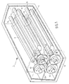
- Fig. 1 is a schematic perspective view of a vibrating device according to the invention, certain parts of which have been left out so as to show parts disposed therebehind.
- Fig. 2 is a side elevation of the device that is shown in Fig. 1, a wall of the housing of which has been left out.
- Fig. 3 shows a diagram for controlling the driving units.
- Figs. 4 and 5 show two different relative positions that the eccentric weights may take up with respect to each other.
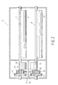
- Fig. 6 is a sectional view of a second embodiment of a vibrating device according to the invention.
- the weights 2, 3, 4, 5 are mounted on shafts 6, 7, 8 and 9, respectively, which extend parallel to each other and which are mounted in bearings (not shown) in such a manner that the shafts 6-9 are rotatable about their central axes, which form axes of rotation for the eccentric weights.
- the two eccentric weights 2 and 3 form a first pair of cooperating eccentric weights, which weights 2 and 3 are coupled by means of meshing gears 10 and 11 mounted on the shafts 6, 7.
- the eccentric weights 4 and 5 are coupled in a similar manner by means of meshing gears 12 and 13 mounted on the shafts 8 and 9.
- a further gear 14 mounted on the shaft 7 of the eccentric weight 3 meshes with a gear 17 mounted on the outgoing shaft 15 of a hydraulic motor 16.
- a gear 18 is mounted on the shaft 9 of the eccentric weight 5, which gear meshes with a gear 19 mounted on the outgoing shaft 20 of a hydraulic motor 21.
- the eccentric weights 2 and 3 will be driven by means of the hydraulic motor 16, in such a manner that they will rotate in the direction indicated by the arrows A and B. Furthermore, the eccentric weights 4 and 5 will be driven by means of the hydraulic motor 21 during operation, in such a manner that they will rotate in the direction indicated by the arrows C and D.
- the space in which the gears are accommodated may be separated from the remaining part of the housing 1 by means of a partition 22 (schematically indicated). Said space may furthermore be divided into two parts by a further partition 23, so that the gears used for driving one pair of eccentric weights 2 and 3 are disposed in a space or housing part that is separated from the space or the housing part in which the gears for driving the other are disposed. This achieves that any damage to gears driving a pair of eccentric weights 2, 3 or 4, 5 will not affect the gears driving the other pair of eccentric weights.
- the hydraulic motor 16 that drives the pair of eccentric weights 2 and 3 is positioned between the axes of rotation of the eccentric weights 2 and 3, seen in a direction perpendicular to the plane through the axes of rotation of said eccentric weights 2 and 3.
- the central axes or axes of rotation of the two hydraulic motors 16 and 21 are furthermore spaced apart by a distance smaller than the distance between the plane through the axes of rotation of the pair of eccentric weights 2, 3 and the plane through the axes of rotation of the pair of eccentric weights 4 and 5.
- This arrangement enables a compact construction of the vibrating device, whilst said arrangement furthermore makes it possible to have the eccentric weights extend in the longitudinal direction of the housing 1 without this leading to undesirable dimensions of the housing. It is possible, therefore, to use eccentric weights of comparatively great length, which enables the use of heavy counterweights without the outer circumference of the path described by the counterweights during operation becoming too large.
- fluid will be supplied to the two hydraulic motors 16 and 21 by means of a pump 24 via a valve mechanism 25.
- the hydraulic motors 16 and 21 and the valve block 25 are connected to a control unit 27, which measures the rotational speed of the two motors 16 and 21 during operation and which is capable of influencing said rotational speed of the two motors 16 and 21 by controlling the supply of fluid to the motors 16 and 21 via the valve mechanism.
- the control unit 27 may comprise a computer, which receives signals from the motors by electric/electronic means and which controls valves by electric/electronic means for the purpose of regulating the fluid flow to the motors.
- the eccentric weights 2 and 3 of one pair and the eccentric weights 4 and 5 of the other pair will take up the relative position that is indicated in Fig. 1 with respect to each other so as to effect a vibrating force in the direction indicated by the arrow E.
- the control unit 27 will effect a supply of fluid to the hydraulic motors 16 and 21 such that the eccentric weights will all rotate at the same rotational speed.
- the eccentric weights are preferably moved to the relative position that is shown in Fig. 4 with respect to each other, so as to eliminate the vibrating force, before the vibrating device is turned off.
- the valve mechanism 25 is influenced by means of the control unit 27 in such a manner that one hydraulic motor is briefly supplied with more fluid or less fluid than the other hydraulic motor, so that the eccentric weights of one pair will briefly rotate slightly more quickly or more slowly than the eccentric weights of the other pair for the purpose of changing the relative position of the eccentric weights of the two groups with respect to each other. Subsequently, the rotational speed of the two pairs of eccentric weights can be simultaneously reduced to zero and the vibrating machine can be stopped.
- the eccentric weights of the two pairs will generally return to the relative position that is shown in Fig. 5 with respect to each other under the influence of the force of gravity and leakage of oil from the hydraulic motors 16 and 21.
- the control unit 27 it is therefore arranged by means of the control unit 27 that one hydraulic motor is briefly supplied with more fluid or less fluid than the other hydraulic motor so as to achieve the relative position of the eccentric weights that is shown in Fig. 4 with respect to each other, so that no vibrating force will be exerted while the rotational speed of the eccentric weights is being increased to the operating speed.
- control unit 27 which monitors and controls the rotational speeds of the hydraulic motors and the supply of fluid to the hydraulic motors, makes it possible to adjust the relative position of the two pairs of eccentric weights with respect to each other in a simple manner without using complicated mechanical means, which makes the construction of the vibrating device simpler and less vulnerable than that of the known devices.
- the direction in which the vibrating force acts can be changed by reversing the direction of rotation of the eccentric weights.
- Fig. 6 shows a second embodiment of the vibrating device according to the invention.
- those parts that correspond to parts shown in the preceding figures and described above are indicated by the same numerals as used in Figs. 1-5.
- the gears connected to the eccentric weights 2 and 3 and the motor 16 that drives said eccentric weights are disposed near one end of the housing 1 in this embodiment, whilst the gears connected to the eccentric weights 4 and 5 and the motor 21 that drives said eccentric weights are disposed near the other end of the housing 1.
- the gear 17 that is mounted on the outgoing shaft of the motor 16 directly meshes with one of the gears connected to the eccentric weights 2 and 3, whilst the gear 19 mounted on the outgoing shaft of the motor 21 directly meshes with one of the gears connected to the eccentric weights 4 and 5.
- the ends of the shafts supporting the eccentric weights are mounted in bearings 28, which are disposed in covers 29 that close the housing 1 at the end thereof.
- Two partitions 30 extending parallel to the covers are disposed in the housing at some distance from the two covers 29, in such a manner that the gears are disposed in a space separated from the space that accommodates the eccentric weights at the two ends of the housing 1.
- Division plates 31 are furthermore provided between the covers 29 and the partitions 30 halfway the height of the space, so that the space accommodating the gears associated with one pair of eccentric weights is separated from the ends of the shafts of the other pair of eccentric weights present at the corresponding end of the housing 1.
- Fig. 6 furthermore shows a clamping device 32, by means of which the vibrating device can be clamped down to a sheet pile or the like, for example.
- the vibrating device is in particular intended for being used for driving piles or the like into the ground or removing piles and the like from the ground, but it will be apparent that the vibrating device may also be used for other purposes.
Landscapes
- Engineering & Computer Science (AREA)
- Mechanical Engineering (AREA)
- Apparatuses For Generation Of Mechanical Vibrations (AREA)
- Placing Or Removing Of Piles Or Sheet Piles, Or Accessories Thereof (AREA)
Applications Claiming Priority (2)
| Application Number | Priority Date | Filing Date | Title |
|---|---|---|---|
| NL1023574 | 2003-05-30 | ||
| NL1023574A NL1023574C2 (nl) | 2003-05-30 | 2003-05-30 | Trilinrichting. |
Publications (2)
| Publication Number | Publication Date |
|---|---|
| EP1481739A1 true EP1481739A1 (de) | 2004-12-01 |
| EP1481739B1 EP1481739B1 (de) | 2011-07-20 |
Family
ID=33129168
Family Applications (1)
| Application Number | Title | Priority Date | Filing Date |
|---|---|---|---|
| EP04076398A Revoked EP1481739B1 (de) | 2003-05-30 | 2004-05-11 | Ein vibrierende Vorrichtung mit zwei Paar zwei exzentrischen Gewichten |
Country Status (3)
| Country | Link |
|---|---|
| EP (1) | EP1481739B1 (de) |
| AT (1) | ATE516892T1 (de) |
| NL (1) | NL1023574C2 (de) |
Cited By (5)
| Publication number | Priority date | Publication date | Assignee | Title |
|---|---|---|---|---|
| EP1867402A1 (de) * | 2006-06-15 | 2007-12-19 | Visam S.r.l. | Verbessertes Vibrationsgenerator |
| EP2881516B1 (de) | 2013-12-03 | 2016-08-31 | BOMAG GmbH & Co. OHG | Bodenverdichtungsmaschine |
| EP3165290A1 (de) * | 2015-11-06 | 2017-05-10 | BAUER Maschinen GmbH | Schwingungserzeuger und verfahren zum einbringen eines rammgutes in einen boden |
| EP3566784B1 (de) * | 2018-05-08 | 2023-03-01 | Terex GB Limited | Einstellbares vibrierendes antriebssystem |
| CN115739247A (zh) * | 2022-12-09 | 2023-03-07 | 连云港市第一人民医院 | 一种防凝的医疗检验用采血管放置装置及其使用方法 |
Citations (6)
| Publication number | Priority date | Publication date | Assignee | Title |
|---|---|---|---|---|
| FR54751E (fr) * | 1946-05-15 | 1950-08-01 | Appareil générateur de vibrations | |
| DE1149304B (de) * | 1957-04-03 | 1963-05-22 | Losenhausenwerk Duesseldorfer | Bodenverdichter mit einem Unwuchtruettler zur Erzeugung gerichteter Schwingungen |
| US3292835A (en) * | 1964-03-28 | 1966-12-20 | Philips Corp | Vibratory drive for intermittent tape transport |
| DE2919987A1 (de) * | 1979-05-17 | 1980-11-20 | Wacker Werke Kg | Von einem hydromotor angetriebener unwuchtvibrator |
| EP1038068B1 (de) * | 1998-03-19 | 2001-06-13 | International Construction Equipment B.V. | Vorrichtung und verfahren zum vibrieren eines objektes |
| US6504278B1 (en) * | 1998-05-08 | 2003-01-07 | Gedib Ingenieurburo Und Innovationsberatung Gmbh | Regulating device for adjusting the static moment resulting from unbalanced mass vibration generators |
-
2003
- 2003-05-30 NL NL1023574A patent/NL1023574C2/nl not_active IP Right Cessation
-
2004
- 2004-05-11 AT AT04076398T patent/ATE516892T1/de not_active IP Right Cessation
- 2004-05-11 EP EP04076398A patent/EP1481739B1/de not_active Revoked
Patent Citations (6)
| Publication number | Priority date | Publication date | Assignee | Title |
|---|---|---|---|---|
| FR54751E (fr) * | 1946-05-15 | 1950-08-01 | Appareil générateur de vibrations | |
| DE1149304B (de) * | 1957-04-03 | 1963-05-22 | Losenhausenwerk Duesseldorfer | Bodenverdichter mit einem Unwuchtruettler zur Erzeugung gerichteter Schwingungen |
| US3292835A (en) * | 1964-03-28 | 1966-12-20 | Philips Corp | Vibratory drive for intermittent tape transport |
| DE2919987A1 (de) * | 1979-05-17 | 1980-11-20 | Wacker Werke Kg | Von einem hydromotor angetriebener unwuchtvibrator |
| EP1038068B1 (de) * | 1998-03-19 | 2001-06-13 | International Construction Equipment B.V. | Vorrichtung und verfahren zum vibrieren eines objektes |
| US6504278B1 (en) * | 1998-05-08 | 2003-01-07 | Gedib Ingenieurburo Und Innovationsberatung Gmbh | Regulating device for adjusting the static moment resulting from unbalanced mass vibration generators |
Cited By (8)
| Publication number | Priority date | Publication date | Assignee | Title |
|---|---|---|---|---|
| EP1867402A1 (de) * | 2006-06-15 | 2007-12-19 | Visam S.r.l. | Verbessertes Vibrationsgenerator |
| EP2881516B1 (de) | 2013-12-03 | 2016-08-31 | BOMAG GmbH & Co. OHG | Bodenverdichtungsmaschine |
| CN104695310B (zh) * | 2013-12-03 | 2019-11-15 | 宝马格有限公司 | 用于振动压路机的激振器和具有该激振器的施工机械 |
| EP2881516B2 (de) † | 2013-12-03 | 2020-03-25 | BOMAG GmbH & Co. OHG | Bodenverdichtungsmaschine |
| EP3165290A1 (de) * | 2015-11-06 | 2017-05-10 | BAUER Maschinen GmbH | Schwingungserzeuger und verfahren zum einbringen eines rammgutes in einen boden |
| WO2017076525A1 (de) | 2015-11-06 | 2017-05-11 | Bauer Maschinen Gmbh | Schwingungserzeuger und verfahren zum einbringen eines rammgutes in einen boden |
| EP3566784B1 (de) * | 2018-05-08 | 2023-03-01 | Terex GB Limited | Einstellbares vibrierendes antriebssystem |
| CN115739247A (zh) * | 2022-12-09 | 2023-03-07 | 连云港市第一人民医院 | 一种防凝的医疗检验用采血管放置装置及其使用方法 |
Also Published As
| Publication number | Publication date |
|---|---|
| EP1481739B1 (de) | 2011-07-20 |
| NL1023574C2 (nl) | 2004-12-01 |
| ATE516892T1 (de) | 2011-08-15 |
Similar Documents
| Publication | Publication Date | Title |
|---|---|---|
| JP2677692B2 (ja) | 無段階調整可能な流体静力学的運転装置及びその運転方法 | |
| JP5380234B2 (ja) | 連続調整可能な振動振幅及び/又は起振力を有する、円振動又は方向性振動を発生する装置 | |
| JP2991693B2 (ja) | 輪転印刷機の印刷装置のための駆動装置 | |
| CN100543226C (zh) | 移动造纸机的辊的设备 | |
| SA02230482B1 (ar) | فاصل حاجز هزاز | |
| NO329992B1 (no) | Motorstyresystem for vibrerende siktseparator | |
| EP1481739B1 (de) | Ein vibrierende Vorrichtung mit zwei Paar zwei exzentrischen Gewichten | |
| US11926974B2 (en) | Interchangeable unit for texturing ground surface work and road construction machine having such an interchangeable unit | |
| JP2727202B2 (ja) | 開放回路を有する二次制御液圧駆動装置 | |
| JP6363667B2 (ja) | 起振機及び杭の施工方法 | |
| CN107427863B (zh) | 振动器 | |
| US5458204A (en) | Vibration pile driver for ramming and/or pulling of ram material | |
| JP3928096B2 (ja) | 傾斜テーブル装置 | |
| US20110110725A1 (en) | Vibratory pile driving apparatus | |
| JP2012135841A (ja) | ガラス板の連続研磨装置及び連続研磨方法 | |
| US20250025916A1 (en) | Soil Compaction Device and Phase-Adjustable Unbalance Exciter with Two Driven Shafts | |
| CN114072244B (zh) | 振动发生器及具有这种振动发生器的建筑机械 | |
| WO2003097940A1 (en) | Drum of vibratory roller provided with vibratory mechanism with directed vibration | |
| CN1254321C (zh) | 轧机的传动系统 | |
| NL7906712A (nl) | Werkwijze voor het regelen van de werphoek van een trilzeef of -toevoerinrichting. | |
| EP2724966A1 (de) | Verfahren zum Rütteln von gestapeltem, blattförmigem Gut mittels eines Rütteltisches sowie Vorrichtung zur Durchführung des Verfahrens | |
| JPH0759948B2 (ja) | 複数の油圧駆動ユニットから成る駆動アッセンブリー用の制御装置 | |
| EP0519884A1 (de) | Walke mit innerhalb des Walzenmantels angeordnetem Antriebsmotor | |
| CN223116767U (zh) | 一种茶叶包装机的振动给料装置 | |
| JPH07109387B2 (ja) | 材料試験機 |
Legal Events
| Date | Code | Title | Description |
|---|---|---|---|
| PUAI | Public reference made under article 153(3) epc to a published international application that has entered the european phase |
Free format text: ORIGINAL CODE: 0009012 |
|
| AK | Designated contracting states |
Kind code of ref document: A1 Designated state(s): AT BE BG CH CY CZ DE DK EE ES FI FR GB GR HU IE IT LI LU MC NL PL PT RO SE SI SK TR |
|
| AX | Request for extension of the european patent |
Extension state: AL HR LT LV MK |
|
| 17P | Request for examination filed |
Effective date: 20050204 |
|
| AKX | Designation fees paid |
Designated state(s): AT BE BG CH CY CZ DE DK EE ES FI FR GB GR HU IE IT LI LU MC NL PL PT RO SE SI SK TR |
|
| 17Q | First examination report despatched |
Effective date: 20100325 |
|
| GRAP | Despatch of communication of intention to grant a patent |
Free format text: ORIGINAL CODE: EPIDOSNIGR1 |
|
| GRAS | Grant fee paid |
Free format text: ORIGINAL CODE: EPIDOSNIGR3 |
|
| GRAA | (expected) grant |
Free format text: ORIGINAL CODE: 0009210 |
|
| AK | Designated contracting states |
Kind code of ref document: B1 Designated state(s): AT BE BG CH CY CZ DE DK EE ES FI FR GB GR HU IE IT LI LU MC NL PL PT RO SE SI SK TR |
|
| REG | Reference to a national code |
Ref country code: GB Ref legal event code: FG4D |
|
| REG | Reference to a national code |
Ref country code: CH Ref legal event code: EP |
|
| REG | Reference to a national code |
Ref country code: DE Ref legal event code: R096 Ref document number: 602004033519 Country of ref document: DE Effective date: 20110915 |
|
| REG | Reference to a national code |
Ref country code: NL Ref legal event code: VDEP Effective date: 20110720 |
|
| REG | Reference to a national code |
Ref country code: AT Ref legal event code: MK05 Ref document number: 516892 Country of ref document: AT Kind code of ref document: T Effective date: 20110720 |
|
| PG25 | Lapsed in a contracting state [announced via postgrant information from national office to epo] |
Ref country code: SE Free format text: LAPSE BECAUSE OF FAILURE TO SUBMIT A TRANSLATION OF THE DESCRIPTION OR TO PAY THE FEE WITHIN THE PRESCRIBED TIME-LIMIT Effective date: 20110720 Ref country code: FI Free format text: LAPSE BECAUSE OF FAILURE TO SUBMIT A TRANSLATION OF THE DESCRIPTION OR TO PAY THE FEE WITHIN THE PRESCRIBED TIME-LIMIT Effective date: 20110720 Ref country code: NL Free format text: LAPSE BECAUSE OF FAILURE TO SUBMIT A TRANSLATION OF THE DESCRIPTION OR TO PAY THE FEE WITHIN THE PRESCRIBED TIME-LIMIT Effective date: 20110720 Ref country code: BE Free format text: LAPSE BECAUSE OF FAILURE TO SUBMIT A TRANSLATION OF THE DESCRIPTION OR TO PAY THE FEE WITHIN THE PRESCRIBED TIME-LIMIT Effective date: 20110720 Ref country code: PT Free format text: LAPSE BECAUSE OF FAILURE TO SUBMIT A TRANSLATION OF THE DESCRIPTION OR TO PAY THE FEE WITHIN THE PRESCRIBED TIME-LIMIT Effective date: 20111121 |
|
| PG25 | Lapsed in a contracting state [announced via postgrant information from national office to epo] |
Ref country code: SI Free format text: LAPSE BECAUSE OF FAILURE TO SUBMIT A TRANSLATION OF THE DESCRIPTION OR TO PAY THE FEE WITHIN THE PRESCRIBED TIME-LIMIT Effective date: 20110720 Ref country code: CY Free format text: LAPSE BECAUSE OF FAILURE TO SUBMIT A TRANSLATION OF THE DESCRIPTION OR TO PAY THE FEE WITHIN THE PRESCRIBED TIME-LIMIT Effective date: 20110720 Ref country code: GR Free format text: LAPSE BECAUSE OF FAILURE TO SUBMIT A TRANSLATION OF THE DESCRIPTION OR TO PAY THE FEE WITHIN THE PRESCRIBED TIME-LIMIT Effective date: 20111021 Ref country code: PL Free format text: LAPSE BECAUSE OF FAILURE TO SUBMIT A TRANSLATION OF THE DESCRIPTION OR TO PAY THE FEE WITHIN THE PRESCRIBED TIME-LIMIT Effective date: 20110720 Ref country code: AT Free format text: LAPSE BECAUSE OF FAILURE TO SUBMIT A TRANSLATION OF THE DESCRIPTION OR TO PAY THE FEE WITHIN THE PRESCRIBED TIME-LIMIT Effective date: 20110720 |
|
| PLBI | Opposition filed |
Free format text: ORIGINAL CODE: 0009260 |
|
| PG25 | Lapsed in a contracting state [announced via postgrant information from national office to epo] |
Ref country code: CZ Free format text: LAPSE BECAUSE OF FAILURE TO SUBMIT A TRANSLATION OF THE DESCRIPTION OR TO PAY THE FEE WITHIN THE PRESCRIBED TIME-LIMIT Effective date: 20110720 Ref country code: SK Free format text: LAPSE BECAUSE OF FAILURE TO SUBMIT A TRANSLATION OF THE DESCRIPTION OR TO PAY THE FEE WITHIN THE PRESCRIBED TIME-LIMIT Effective date: 20110720 |
|
| 26 | Opposition filed |
Opponent name: THYSSENKRUPP GFT TIEFBAUTECHNIK GBMH Effective date: 20120328 |
|
| PLAX | Notice of opposition and request to file observation + time limit sent |
Free format text: ORIGINAL CODE: EPIDOSNOBS2 |
|
| PG25 | Lapsed in a contracting state [announced via postgrant information from national office to epo] |
Ref country code: EE Free format text: LAPSE BECAUSE OF FAILURE TO SUBMIT A TRANSLATION OF THE DESCRIPTION OR TO PAY THE FEE WITHIN THE PRESCRIBED TIME-LIMIT Effective date: 20110720 Ref country code: RO Free format text: LAPSE BECAUSE OF FAILURE TO SUBMIT A TRANSLATION OF THE DESCRIPTION OR TO PAY THE FEE WITHIN THE PRESCRIBED TIME-LIMIT Effective date: 20110720 |
|
| REG | Reference to a national code |
Ref country code: DE Ref legal event code: R026 Ref document number: 602004033519 Country of ref document: DE Effective date: 20120328 |
|
| PG25 | Lapsed in a contracting state [announced via postgrant information from national office to epo] |
Ref country code: DK Free format text: LAPSE BECAUSE OF FAILURE TO SUBMIT A TRANSLATION OF THE DESCRIPTION OR TO PAY THE FEE WITHIN THE PRESCRIBED TIME-LIMIT Effective date: 20110720 |
|
| PGFP | Annual fee paid to national office [announced via postgrant information from national office to epo] |
Ref country code: DE Payment date: 20120523 Year of fee payment: 9 |
|
| PG25 | Lapsed in a contracting state [announced via postgrant information from national office to epo] |
Ref country code: MC Free format text: LAPSE BECAUSE OF NON-PAYMENT OF DUE FEES Effective date: 20120531 |
|
| REG | Reference to a national code |
Ref country code: CH Ref legal event code: PL |
|
| GBPC | Gb: european patent ceased through non-payment of renewal fee |
Effective date: 20120511 |
|
| PG25 | Lapsed in a contracting state [announced via postgrant information from national office to epo] |
Ref country code: LI Free format text: LAPSE BECAUSE OF NON-PAYMENT OF DUE FEES Effective date: 20120531 Ref country code: CH Free format text: LAPSE BECAUSE OF NON-PAYMENT OF DUE FEES Effective date: 20120531 |
|
| REG | Reference to a national code |
Ref country code: IE Ref legal event code: MM4A |
|
| PG25 | Lapsed in a contracting state [announced via postgrant information from national office to epo] |
Ref country code: IT Free format text: LAPSE BECAUSE OF NON-PAYMENT OF DUE FEES Effective date: 20120511 |
|
| REG | Reference to a national code |
Ref country code: FR Ref legal event code: ST Effective date: 20130131 |
|
| PG25 | Lapsed in a contracting state [announced via postgrant information from national office to epo] |
Ref country code: FR Free format text: LAPSE BECAUSE OF NON-PAYMENT OF DUE FEES Effective date: 20120531 Ref country code: IE Free format text: LAPSE BECAUSE OF NON-PAYMENT OF DUE FEES Effective date: 20120511 Ref country code: GB Free format text: LAPSE BECAUSE OF NON-PAYMENT OF DUE FEES Effective date: 20120511 Ref country code: ES Free format text: LAPSE BECAUSE OF FAILURE TO SUBMIT A TRANSLATION OF THE DESCRIPTION OR TO PAY THE FEE WITHIN THE PRESCRIBED TIME-LIMIT Effective date: 20111031 |
|
| PG25 | Lapsed in a contracting state [announced via postgrant information from national office to epo] |
Ref country code: BG Free format text: LAPSE BECAUSE OF FAILURE TO SUBMIT A TRANSLATION OF THE DESCRIPTION OR TO PAY THE FEE WITHIN THE PRESCRIBED TIME-LIMIT Effective date: 20111020 |
|
| RDAF | Communication despatched that patent is revoked |
Free format text: ORIGINAL CODE: EPIDOSNREV1 |
|
| PG25 | Lapsed in a contracting state [announced via postgrant information from national office to epo] |
Ref country code: DE Free format text: LAPSE BECAUSE OF NON-PAYMENT OF DUE FEES Effective date: 20131203 |
|
| REG | Reference to a national code |
Ref country code: DE Ref legal event code: R119 Ref document number: 602004033519 Country of ref document: DE Effective date: 20131203 |
|
| RDAG | Patent revoked |
Free format text: ORIGINAL CODE: 0009271 |
|
| STAA | Information on the status of an ep patent application or granted ep patent |
Free format text: STATUS: PATENT REVOKED |
|
| PG25 | Lapsed in a contracting state [announced via postgrant information from national office to epo] |
Ref country code: TR Free format text: LAPSE BECAUSE OF FAILURE TO SUBMIT A TRANSLATION OF THE DESCRIPTION OR TO PAY THE FEE WITHIN THE PRESCRIBED TIME-LIMIT Effective date: 20110720 |
|
| 27W | Patent revoked |
Effective date: 20140102 |
|
| PG25 | Lapsed in a contracting state [announced via postgrant information from national office to epo] |
Ref country code: LU Free format text: LAPSE BECAUSE OF NON-PAYMENT OF DUE FEES Effective date: 20120511 |