EP1484517A2 - Rolling bearing, cam follower with roller, and cam - Google Patents
Rolling bearing, cam follower with roller, and cam Download PDFInfo
- Publication number
- EP1484517A2 EP1484517A2 EP04013289A EP04013289A EP1484517A2 EP 1484517 A2 EP1484517 A2 EP 1484517A2 EP 04013289 A EP04013289 A EP 04013289A EP 04013289 A EP04013289 A EP 04013289A EP 1484517 A2 EP1484517 A2 EP 1484517A2
- Authority
- EP
- European Patent Office
- Prior art keywords
- roller
- cam
- follower
- shaft
- rolling
- Prior art date
- Legal status (The legal status is an assumption and is not a legal conclusion. Google has not performed a legal analysis and makes no representation as to the accuracy of the status listed.)
- Granted
Links
Images


Classifications
-
- F—MECHANICAL ENGINEERING; LIGHTING; HEATING; WEAPONS; BLASTING
- F01—MACHINES OR ENGINES IN GENERAL; ENGINE PLANTS IN GENERAL; STEAM ENGINES
- F01L—CYCLICALLY OPERATING VALVES FOR MACHINES OR ENGINES
- F01L1/00—Valve-gear or valve arrangements, e.g. lift-valve gear
- F01L1/12—Transmitting gear between valve drive and valve
- F01L1/18—Rocking arms or levers
- F01L1/181—Centre pivot rocking arms
-
- C—CHEMISTRY; METALLURGY
- C21—METALLURGY OF IRON
- C21D—MODIFYING THE PHYSICAL STRUCTURE OF FERROUS METALS; GENERAL DEVICES FOR HEAT TREATMENT OF FERROUS OR NON-FERROUS METALS OR ALLOYS; MAKING METAL MALLEABLE, e.g. BY DECARBURISATION OR TEMPERING
- C21D1/00—General methods or devices for heat treatment, e.g. annealing, hardening, quenching or tempering
- C21D1/78—Combined heat-treatments not provided for above
-
- C—CHEMISTRY; METALLURGY
- C21—METALLURGY OF IRON
- C21D—MODIFYING THE PHYSICAL STRUCTURE OF FERROUS METALS; GENERAL DEVICES FOR HEAT TREATMENT OF FERROUS OR NON-FERROUS METALS OR ALLOYS; MAKING METAL MALLEABLE, e.g. BY DECARBURISATION OR TEMPERING
- C21D9/00—Heat treatment, e.g. annealing, hardening, quenching or tempering, adapted for particular articles; Furnaces therefor
- C21D9/0068—Heat treatment, e.g. annealing, hardening, quenching or tempering, adapted for particular articles; Furnaces therefor for particular articles not mentioned below
-
- C—CHEMISTRY; METALLURGY
- C23—COATING METALLIC MATERIAL; COATING MATERIAL WITH METALLIC MATERIAL; CHEMICAL SURFACE TREATMENT; DIFFUSION TREATMENT OF METALLIC MATERIAL; COATING BY VACUUM EVAPORATION, BY SPUTTERING, BY ION IMPLANTATION OR BY CHEMICAL VAPOUR DEPOSITION, IN GENERAL; INHIBITING CORROSION OF METALLIC MATERIAL OR INCRUSTATION IN GENERAL
- C23C—COATING METALLIC MATERIAL; COATING MATERIAL WITH METALLIC MATERIAL; SURFACE TREATMENT OF METALLIC MATERIAL BY DIFFUSION INTO THE SURFACE, BY CHEMICAL CONVERSION OR SUBSTITUTION; COATING BY VACUUM EVAPORATION, BY SPUTTERING, BY ION IMPLANTATION OR BY CHEMICAL VAPOUR DEPOSITION, IN GENERAL
- C23C8/00—Solid state diffusion of only non-metal elements into metallic material surfaces; Chemical surface treatment of metallic material by reaction of the surface with a reactive gas, leaving reaction products of surface material in the coating, e.g. conversion coatings, passivation of metals
- C23C8/06—Solid state diffusion of only non-metal elements into metallic material surfaces; Chemical surface treatment of metallic material by reaction of the surface with a reactive gas, leaving reaction products of surface material in the coating, e.g. conversion coatings, passivation of metals using gases
- C23C8/08—Solid state diffusion of only non-metal elements into metallic material surfaces; Chemical surface treatment of metallic material by reaction of the surface with a reactive gas, leaving reaction products of surface material in the coating, e.g. conversion coatings, passivation of metals using gases only one element being applied
- C23C8/24—Nitriding
- C23C8/26—Nitriding of ferrous surfaces
-
- C—CHEMISTRY; METALLURGY
- C23—COATING METALLIC MATERIAL; COATING MATERIAL WITH METALLIC MATERIAL; CHEMICAL SURFACE TREATMENT; DIFFUSION TREATMENT OF METALLIC MATERIAL; COATING BY VACUUM EVAPORATION, BY SPUTTERING, BY ION IMPLANTATION OR BY CHEMICAL VAPOUR DEPOSITION, IN GENERAL; INHIBITING CORROSION OF METALLIC MATERIAL OR INCRUSTATION IN GENERAL
- C23C—COATING METALLIC MATERIAL; COATING MATERIAL WITH METALLIC MATERIAL; SURFACE TREATMENT OF METALLIC MATERIAL BY DIFFUSION INTO THE SURFACE, BY CHEMICAL CONVERSION OR SUBSTITUTION; COATING BY VACUUM EVAPORATION, BY SPUTTERING, BY ION IMPLANTATION OR BY CHEMICAL VAPOUR DEPOSITION, IN GENERAL
- C23C8/00—Solid state diffusion of only non-metal elements into metallic material surfaces; Chemical surface treatment of metallic material by reaction of the surface with a reactive gas, leaving reaction products of surface material in the coating, e.g. conversion coatings, passivation of metals
- C23C8/06—Solid state diffusion of only non-metal elements into metallic material surfaces; Chemical surface treatment of metallic material by reaction of the surface with a reactive gas, leaving reaction products of surface material in the coating, e.g. conversion coatings, passivation of metals using gases
- C23C8/28—Solid state diffusion of only non-metal elements into metallic material surfaces; Chemical surface treatment of metallic material by reaction of the surface with a reactive gas, leaving reaction products of surface material in the coating, e.g. conversion coatings, passivation of metals using gases more than one element being applied in one step
- C23C8/30—Carbo-nitriding
- C23C8/32—Carbo-nitriding of ferrous surfaces
-
- F—MECHANICAL ENGINEERING; LIGHTING; HEATING; WEAPONS; BLASTING
- F01—MACHINES OR ENGINES IN GENERAL; ENGINE PLANTS IN GENERAL; STEAM ENGINES
- F01L—CYCLICALLY OPERATING VALVES FOR MACHINES OR ENGINES
- F01L1/00—Valve-gear or valve arrangements, e.g. lift-valve gear
- F01L1/12—Transmitting gear between valve drive and valve
- F01L1/14—Tappets; Push rods
- F01L1/146—Push-rods
-
- F—MECHANICAL ENGINEERING; LIGHTING; HEATING; WEAPONS; BLASTING
- F16—ENGINEERING ELEMENTS AND UNITS; GENERAL MEASURES FOR PRODUCING AND MAINTAINING EFFECTIVE FUNCTIONING OF MACHINES OR INSTALLATIONS; THERMAL INSULATION IN GENERAL
- F16C—SHAFTS; FLEXIBLE SHAFTS; ELEMENTS OR CRANKSHAFT MECHANISMS; ROTARY BODIES OTHER THAN GEARING ELEMENTS; BEARINGS
- F16C13/00—Rolls, drums, discs, or the like; Bearings or mountings therefor
- F16C13/006—Guiding rollers, wheels or the like, formed by or on the outer element of a single bearing or bearing unit, e.g. two adjacent bearings, whose ratio of length to diameter is generally less than one
-
- F—MECHANICAL ENGINEERING; LIGHTING; HEATING; WEAPONS; BLASTING
- F16—ENGINEERING ELEMENTS AND UNITS; GENERAL MEASURES FOR PRODUCING AND MAINTAINING EFFECTIVE FUNCTIONING OF MACHINES OR INSTALLATIONS; THERMAL INSULATION IN GENERAL
- F16C—SHAFTS; FLEXIBLE SHAFTS; ELEMENTS OR CRANKSHAFT MECHANISMS; ROTARY BODIES OTHER THAN GEARING ELEMENTS; BEARINGS
- F16C19/00—Bearings with rolling contact, for exclusively rotary movement
- F16C19/22—Bearings with rolling contact, for exclusively rotary movement with bearing rollers essentially of the same size in one or more circular rows, e.g. needle bearings
- F16C19/44—Needle bearings
- F16C19/46—Needle bearings with one row or needles
-
- F—MECHANICAL ENGINEERING; LIGHTING; HEATING; WEAPONS; BLASTING
- F16—ENGINEERING ELEMENTS AND UNITS; GENERAL MEASURES FOR PRODUCING AND MAINTAINING EFFECTIVE FUNCTIONING OF MACHINES OR INSTALLATIONS; THERMAL INSULATION IN GENERAL
- F16C—SHAFTS; FLEXIBLE SHAFTS; ELEMENTS OR CRANKSHAFT MECHANISMS; ROTARY BODIES OTHER THAN GEARING ELEMENTS; BEARINGS
- F16C33/00—Parts of bearings; Special methods for making bearings or parts thereof
- F16C33/30—Parts of ball or roller bearings
- F16C33/58—Raceways; Race rings
- F16C33/62—Selection of substances
-
- F—MECHANICAL ENGINEERING; LIGHTING; HEATING; WEAPONS; BLASTING
- F16—ENGINEERING ELEMENTS AND UNITS; GENERAL MEASURES FOR PRODUCING AND MAINTAINING EFFECTIVE FUNCTIONING OF MACHINES OR INSTALLATIONS; THERMAL INSULATION IN GENERAL
- F16C—SHAFTS; FLEXIBLE SHAFTS; ELEMENTS OR CRANKSHAFT MECHANISMS; ROTARY BODIES OTHER THAN GEARING ELEMENTS; BEARINGS
- F16C33/00—Parts of bearings; Special methods for making bearings or parts thereof
- F16C33/30—Parts of ball or roller bearings
- F16C33/58—Raceways; Race rings
- F16C33/64—Special methods of manufacture
-
- C—CHEMISTRY; METALLURGY
- C21—METALLURGY OF IRON
- C21D—MODIFYING THE PHYSICAL STRUCTURE OF FERROUS METALS; GENERAL DEVICES FOR HEAT TREATMENT OF FERROUS OR NON-FERROUS METALS OR ALLOYS; MAKING METAL MALLEABLE, e.g. BY DECARBURISATION OR TEMPERING
- C21D9/00—Heat treatment, e.g. annealing, hardening, quenching or tempering, adapted for particular articles; Furnaces therefor
- C21D9/30—Heat treatment, e.g. annealing, hardening, quenching or tempering, adapted for particular articles; Furnaces therefor for crankshafts; for camshafts
-
- C—CHEMISTRY; METALLURGY
- C21—METALLURGY OF IRON
- C21D—MODIFYING THE PHYSICAL STRUCTURE OF FERROUS METALS; GENERAL DEVICES FOR HEAT TREATMENT OF FERROUS OR NON-FERROUS METALS OR ALLOYS; MAKING METAL MALLEABLE, e.g. BY DECARBURISATION OR TEMPERING
- C21D9/00—Heat treatment, e.g. annealing, hardening, quenching or tempering, adapted for particular articles; Furnaces therefor
- C21D9/40—Heat treatment, e.g. annealing, hardening, quenching or tempering, adapted for particular articles; Furnaces therefor for rings; for bearing races
-
- F—MECHANICAL ENGINEERING; LIGHTING; HEATING; WEAPONS; BLASTING
- F01—MACHINES OR ENGINES IN GENERAL; ENGINE PLANTS IN GENERAL; STEAM ENGINES
- F01L—CYCLICALLY OPERATING VALVES FOR MACHINES OR ENGINES
- F01L2301/00—Using particular materials
-
- F—MECHANICAL ENGINEERING; LIGHTING; HEATING; WEAPONS; BLASTING
- F01—MACHINES OR ENGINES IN GENERAL; ENGINE PLANTS IN GENERAL; STEAM ENGINES
- F01L—CYCLICALLY OPERATING VALVES FOR MACHINES OR ENGINES
- F01L2303/00—Manufacturing of components used in valve arrangements
-
- F—MECHANICAL ENGINEERING; LIGHTING; HEATING; WEAPONS; BLASTING
- F01—MACHINES OR ENGINES IN GENERAL; ENGINE PLANTS IN GENERAL; STEAM ENGINES
- F01L—CYCLICALLY OPERATING VALVES FOR MACHINES OR ENGINES
- F01L2305/00—Valve arrangements comprising rollers
-
- F—MECHANICAL ENGINEERING; LIGHTING; HEATING; WEAPONS; BLASTING
- F01—MACHINES OR ENGINES IN GENERAL; ENGINE PLANTS IN GENERAL; STEAM ENGINES
- F01L—CYCLICALLY OPERATING VALVES FOR MACHINES OR ENGINES
- F01L2305/00—Valve arrangements comprising rollers
- F01L2305/02—Mounting of rollers
-
- F—MECHANICAL ENGINEERING; LIGHTING; HEATING; WEAPONS; BLASTING
- F16—ENGINEERING ELEMENTS AND UNITS; GENERAL MEASURES FOR PRODUCING AND MAINTAINING EFFECTIVE FUNCTIONING OF MACHINES OR INSTALLATIONS; THERMAL INSULATION IN GENERAL
- F16C—SHAFTS; FLEXIBLE SHAFTS; ELEMENTS OR CRANKSHAFT MECHANISMS; ROTARY BODIES OTHER THAN GEARING ELEMENTS; BEARINGS
- F16C2240/00—Specified values or numerical ranges of parameters; Relations between them
- F16C2240/90—Surface areas
-
- F—MECHANICAL ENGINEERING; LIGHTING; HEATING; WEAPONS; BLASTING
- F16—ENGINEERING ELEMENTS AND UNITS; GENERAL MEASURES FOR PRODUCING AND MAINTAINING EFFECTIVE FUNCTIONING OF MACHINES OR INSTALLATIONS; THERMAL INSULATION IN GENERAL
- F16C—SHAFTS; FLEXIBLE SHAFTS; ELEMENTS OR CRANKSHAFT MECHANISMS; ROTARY BODIES OTHER THAN GEARING ELEMENTS; BEARINGS
- F16C2360/00—Engines or pumps
- F16C2360/18—Camshafts
-
- F—MECHANICAL ENGINEERING; LIGHTING; HEATING; WEAPONS; BLASTING
- F16—ENGINEERING ELEMENTS AND UNITS; GENERAL MEASURES FOR PRODUCING AND MAINTAINING EFFECTIVE FUNCTIONING OF MACHINES OR INSTALLATIONS; THERMAL INSULATION IN GENERAL
- F16H—GEARING
- F16H53/00—Cams or cam-followers, e.g. rollers for gearing mechanisms
- F16H53/06—Cam-followers
-
- Y—GENERAL TAGGING OF NEW TECHNOLOGICAL DEVELOPMENTS; GENERAL TAGGING OF CROSS-SECTIONAL TECHNOLOGIES SPANNING OVER SEVERAL SECTIONS OF THE IPC; TECHNICAL SUBJECTS COVERED BY FORMER USPC CROSS-REFERENCE ART COLLECTIONS [XRACs] AND DIGESTS
- Y10—TECHNICAL SUBJECTS COVERED BY FORMER USPC
- Y10T—TECHNICAL SUBJECTS COVERED BY FORMER US CLASSIFICATION
- Y10T74/00—Machine element or mechanism
- Y10T74/21—Elements
- Y10T74/2101—Cams
- Y10T74/2107—Follower
Definitions
- the present invention relates to a rolling bearing, a cam-follower with roller employing the rolling bearing, and a cam.
- a full type roller bearing without cage such as a bearing for a rocker arm among rolling bearings
- the full type roller bearing and other rolling bearings are not particularly distinguished, and both are referred to as a rolling bearing herein.
- a rolling bearing In the rolling bearing without cage, interference among rollers is inevitable, and a lubricant is not sufficiently supplied to the inside of the bearing. Accordingly, separation originating from a surface of a roller or a race may occur.
- An object of the present invention is to provide a rolling bearing that attains long life against surface damage such as surface-originating separation or internally originating separation under harsh condition of use and allows facilitated caulking work of an end portion, a cam-follower with roller employing the rolling bearing, and a cam.
- a rolling bearing according to the present invention includes an outer member, an inner member located inside the outer member, and a rolling element interposed between the outer member and the inner member. At least one member of the outer member and the inner member has a nitrogen enriched layer. In at least one member, austenite grain size of a surface portion of an area in a rolling contact surface where the rolling element rolls is No. 11 or larger, and an end portion of that member has hardness of at most HV (Vickers hardness) 300.
- austenite grain size of the surface portion in the rolling contact surface is less than No. 11, rolling contact fatigue life under harsh condition of use cannot be extended. Therefore, austenite grain size in the surface portion is set to not smaller than No. 11.
- the nitrogen enriched layer is disposed in order to refine and strengthen microstructure by subjecting the nitrogen enriched layer to high-frequency quenching.
- austenite grain refers to grain of austenite that has undergone phase transformation during quenching and heating, that is, grain that remains as history even after austenite has transformed into martensite by cooling.
- the austenite grain described above may be any austenite grain having a grain boundary that can be observed by subjecting a metal phase sample of a member of interest to a treatment for developing the grain boundary such as etching. In a sense of grain boundary at the time of heating immediately before low-temperature quenching, the austenite grain may be referred to as "prior austenite grain".
- the average of JIS-defined grain size numbers may be converted to obtain an average grain size, or the intercept method or the like may be used, in which a straight line is placed on a metal phase structure in a random direction to obtain an average length between points at which the straight line encounters grain boundaries, followed by multiplying the obtained average length by a correction coefficient so as to obtain a length of three dimension from a length of two dimension.
- the nitrogen enriched layer is formed by nitrocarburizing treatment.
- the nitrogen enriched layer may or may not be enriched with carbon.
- microstructure of the area may contain ferrite and carbide.
- ferrite refers to ⁇ phase of iron, and such ferrite does not contain a dislocation in high density as in martensite. Ferrite generated by slow cooling from austenite (y) phase or ferrite sufficiently tempered after quenching is one example. Carbide such as cementite corresponding to the ferrite with low dislocation density as above is dispersed in an aggregated and coarsened state. Therefore, the microstructure containing the ferrite described above and the carbide adapts to a typical softened state.
- Carbide mainly refers to cementite Fe 3 C.
- the nitrogen enriched layer contains nitrogen to a large extent, though not as much as carbon. Therefore, more appropriately, carbide may cover carbonitride such as Fe 3 (C, N).
- carbide may include the carbonitride.
- a steel product normally contains Mn or the like, such an element is dissolved in carbide and takes a form such as (Fe, Mn) 3 (C, N). Note that such a form is naturally included.
- Mn Fe 3
- Mn carbonitride
- the carbide described above also includes such types of carbide.
- the surface portion of the area in the rolling contact surface may be formed by high-frequency quenching.
- the surface portion can have hardness of at least HV653.
- the surface portion of the area in the rolling contact surface can contain 10 to 50 volume % of retained austenite. In this manner, fracture development due to surface originating separation or internally originating separation can be suppressed. If the retained austenite accounts for less than 10 volume %, long life under harsh condition of use cannot be attained. On the other hand, if the retained austenite accounts for more than 50 volume %, fine retained austenite cannot be obtained. Instead, life under such condition of use may be shortened.
- Measurement of the retained austenite can be performed by using a well-known methods such as X-ray diffraction method and transmission electron microscopy (TEM). Austenite may be measured by using a magnetic measurement device such as magnetic balance, because it is not ferromagnetic as ferrite or cementite.
- a well-known methods such as X-ray diffraction method and transmission electron microscopy (TEM).
- Austenite may be measured by using a magnetic measurement device such as magnetic balance, because it is not ferromagnetic as ferrite or cementite.
- At least one member described above may be subjected to any one of a treatment of carbonitriding the member at A 1 point or higher followed by slow cooling down to a point lower than the A 1 point and then subjecting the surface portion to high-frequency quenching, and a treatment of carbonitriding the member at the A 1 point or higher followed by rapid cooling down to a point lower than the A 1 point, tempering at the point lower than the A 1 point, and subjecting the surface portion to high-frequency quenching.
- the A 1 point described above corresponds to a eutectic temperature, and it is set to 723°C for Fe-C system, for example.
- the A 1 point of the steel product normally used in the rolling bearing is also a temperature around 723°C.
- the surface portion subjected to high-frequency quenching has austenite grain size of No. 11 or larger defined in JIS, contains 10 to 50 volume % of retained austenite, and has hardness of not smaller than HV653. This is because the member is subjected to carbonitriding treatment and because the surface portion thereof including the rolling contact surface is subjected to high-frequency quenching.
- a portion not affected by high-frequency quenching attains hardness of not larger than HV300, because quenching and tempering (tempering) treatment is performed even when slow cooling or rapid cooling is performed after carbonitriding treatment.
- the rolling bearing described above is employed in a cam-follower with roller.
- a roller rolling along an inner circumference of an outer-roller is interposed between the outer-roller serving as the outer member and a shaft serving as the inner member.
- the cam-follower is supported by that shaft.
- a portion where the roller rolls is assumed as the surface portion of the area in the rolling contact surface of the shaft.
- the rolling bearing described above is employed in a cam-follower with roller.
- a shaft of the cam-follower with roller has its end portion subjected to plastic working and is fixed to a roller support member.
- a body of the cam follower may be obtained by press-working.
- press-working is specifically a kind of cold forging and the like.
- a cam according to the present invention abuts on the outer member provided in a rocker arm.
- the surface portion abutting on the outer member of the cam has austenite grain size of No. 11 or larger.
- Fig. 1 is a schematic front view showing a structure of a cam-follower with roller in an engine in an embodiment of the present invention.
- Fig. 2A is a cross-sectional view along the line II-II in Fig. 1.
- a rocker arm 1 which is a pivotable member is rotatably supported by a rocker arm shaft 5 via a bearing metal in the center.
- Adjust screw 7 is inserted and screwed into one end portion 1b of rocker arm 1. Adjust screw 7 is fixed by a locknut 8 and abuts on an upper end of a suction valve or an exhaust valve 9 of an internal combustion engine at its lower end. Valve 9 is biased by resilience of a spring 10.
- Rocker arm 1 has a cam-follower body 50 provided at the other end 1a.
- Cam-follower body 50 is integrated with a roller support portion 14 formed in a bifurcated manner.
- bifurcated roller support portion 14 is provided with a beveled portion 14a.
- opposite ends 2a of a roller shaft 2 representing the inner member are caulked, so as to form caulked portions 25 for fixing.
- at least opposite ends 2a of the roller shaft have hardness not exceeding HV300 so as to allow facilitated caulking, whereby the end portions are subjected to caulking, and caulked fixing portion 25 is formed at the beveled portion of the roller support portion.
- roller shaft 2 In the center of an outer circumferential surface of roller shaft 2, an outer-roller 4 implementing the outer member is rotatably supported, with a roller 3 representing a rolling element interposed.
- Roller 3 implements a bearing interposed between roller shaft 2 and outer-roller 4.
- the bearing interposed between roller shaft 2 and outer-roller 4 may be referred to as a roller.
- An axis direction of roller 3 is arranged in parallel to an axis of the roller shaft.
- An outer circumferential surface of outer-roller 4 abuts on a cam surface of a cam 6 provided on a cam shaft by a biasing force of spring 10.
- a rolling bearing constituted of roller shaft 2, roller 3 and outer-roller 4 is employed as a rolling bearing for rocker arm
- a rolling bearing is generally referred to as a full type roller bearing.
- the rolling bearings are not particularly distinguished.
- the cam-follower with roller in the engine in the embodiment of the present invention is a member including the rolling bearing for rocker arm and the cam-follower body described above.
- roller shaft 2 has a nitrogen enriched layer, of which surface portion of the area in the rolling contact surface of the roller shaft 2 is subjected to high-frequency quenching, and has ultrafine austenite grain size of No. 11 or larger (defined in JIS) as well as hardness of not smaller than HV653.
- a portion other than the surface portion of the area in the rolling contact surface has a relatively coarse ferrite grain size or austenite grain size of not larger than No. 10.
- the end portion of roller shaft 2 has low hardness such as not larger than HV300.
- retained austenite accounts for 10 to 50 volume % therein. As a result, surface damage and internally originating separation are less likely in the surface portion.
- facilitated caulking is allowed.
- Fig. 3 shows a cam-follower with roller in an engine in another embodiment of the present invention.
- roller shaft 2 is fixed in a roller hole (not shown) extending between two sidewalls and opened between one end portion 1b and the other end portion 1a of rocker arm 1.
- One end abuts on an end portion of engine open/close valve 9, while the other end abuts on a not-shown pivot.
- Cam-follower body 50 provided with a pivot receiving portion 15 is biased by spring 10 in a prescribed direction around the valve, and receives a driving force transmitted from cam 6 so as to move valve 9 against the biasing force by the spring.
- Fig. 4 shows a cam-follower with roller in an engine in yet another embodiment of the present invention.
- Fig. 5 is an enlarged view of a portion including the rocker arm rolling bearing in Fig. 4.
- rotation shaft 5 is arranged in the center of rocker arm 1, around which rocker arm 1 pivots.
- End portion 1b of one arm of rocker arm 1 abuts on an end of engine valve 9, while end portion 1a of the other arm abuts on an end of a connecting bar 16.
- Adjust screw 8 attains a function to adjust an abutment position of end portion 1a of the rocker arm and connecting bar 16.
- Cam-follower body 50 is provided in a hollow bearing attachment portion 16a located at a lower end of connecting bar 16.
- the rolling bearing for rocker arm is attached to cam-follower body 50 by means of an attachment member 17.
- Cam 6 abuts on outer-roller 4 of the rolling bearing so as to transmit a driving force to the connecting bar.
- roller shaft 2 representing the inner member is subjected to heat treatment which will be described below, so that the surface portion thereof includes ultrafine austenite grains.
- Roller shaft 2 representing the inner member in Figs. 3 and 5 has a nitrogen enriched layer, of which surface portion of the area in the rolling contact surface is subjected to high-frequency quenching and has ultrafine austenite grain size of No. 11 or larger (defined in JIS) as well as hardness of not smaller than HV653.
- a portion other than the surface portion of the area in the rolling contact surface has a relatively coarse austenite grain size of not larger than No. 10 and low hardness such as not larger than HV300.
- retained austenite accounts for 10 to 50 volume % therein. As a result, surface damage and internally originating separation are less likely in the surface portion.
- facilitated caulking is allowed. Therefore, though not shown, opposite ends of the roller shaft are caulked, so as to form caulked fixing portion in the beveled portion of the roller shaft support portion.
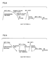
- FIG. 6 illustrates a heat treatment method in the embodiment of the present invention
- Fig. 7 illustrates another heat treatment method in the embodiment of the present invention
- Fig. 6 shows a heat treatment pattern in which carbonitriding treatment is performed at A 1 point or higher followed by slow cooling
- Fig. 7 shows a heat treatment pattern in which carbonitriding treatment is performed followed by rapid cooling, and thereafter quenching and tempering treatment, that is, tempering treatment is performed at a point lower than the A 1 point.
- the inner member in the bearing member and the cam can be subjected to any heat treatment of the above.
- the nitrogen enriched layer which is a "carbonitrided layer” is formed through the carbonitriding treatment in any of the heat treatments described above.
- carbon concentration in steel used as a material in the carbonitriding treatment is high, in some cases, carbon may not readily be introduced into the surface of steel from an atmosphere for a normal carbonitriding treatment.
- a carburized layer attaining a carbon concentration higher than that may be generated, or alternatively, generation of such a carburized layer attaining a carbon concentration higher than that may be unlikely.
- nitrogen concentration in normal steel is as low as not larger than approximately 0.025 wt % at the maximum.
- the nitrogen enriched layer is clearly generated regardless of the carbon concentration in the steel used as a material.
- the microstructure contains ferrite for the purpose of caulking. Accordingly, the carbon concentration is set relatively low, and the nitrogen enriched layer is also enriched with carbon in many cases.
- the carbonitriding treatment is performed at A 1 point or higher, for example.
- the nitrogen enriched layer is formed in a member of interest in the rolling bearing.
- C and N that are interstitial elements with respect to iron atom Fe are introduced in a hypereutectoid manner, and carbide is precipitated in austenite, for example (two phases coexist).
- austenite phase is obtained, depending on a composition of an original steel product used as a material.
- the carbonitriding treatment may be performed at a temperature at which two phases of ferrite and austenite or two phases of austenite and cementite coexist in the steel product used as the material.
- a temperature range for slow cooling may be a range from the carbonitriding treatment temperature to approximately (A 1 point-100°C). Even if slow cooling down to a temperature lower than this range is performed, aggregation and coarsening of cementite cannot be expected. Instead, it is time consuming and inefficient.
- the slow cooling temperature may be approximately 620°C at the lowest. Subsequently, in order to save time, air cooling, water cooling, or oil cooling may be performed.
- pearlite is generated from austenite in carbide+austenite, and carbide in pearlite is aggregated and coarsened.
- heat pattern H2 quenching by oil cooling, for example, is started from the carbonitriding treatment temperature.
- martensite or the like is generated from austenite in the inner portion, depending on a composition of an original steel product.
- the tempering treatment quenching and tempering treatment
- Tempering rapidly progresses at a temperature directly under A 1 point or at a temperature as close as possible to the A 1 point. That is, high-temperature tempering is performed. Therefore, desirably, tempering is performed in a range from the A 1 point to 650°C or more preferably in a range from the A 1 point to 680°C.
- martensite is generated from austenite in (carbide+austenite) by quenching such as oil cooling. Martensite is softened by tempering described above, similarly to martensite generated in the inner portion. Carbide that has originally been present aggregates.
- High-frequency quenching is performed in both heat patterns H1 and H2.
- the nitrogen enriched layer has had the structure in which aggregated carbide (larger ratio) and ferrite have existed in a mixed manner.
- heating is rapid.
- carbide is dissolved and austenite nucleates.
- austenite nucleation density is also very high and grain size in austenite structure formed by impingement of generated austenite is ultrafine.
- carbide also exists therein, which prevents growth of ultrafine austenite grains that have just been generated. In this manner, ultrafine austenite grains can be obtained in the nitrogen enriched layer.
- carbide is dissolved and a larger amount of carbon is dissolved in ultrafine austenite.
- tempering that will not lower hardness to a large extent is performed at approximately 180°C. Tempering at approximately 180°C hardly causes high density dislocation to disappear, that is, density dislocation is maintained. Here, tempering is performed for stabilizing the structure. Tempering as above does not cause aggregation of cementite nor softening. This tempering may not be performed, depending on the steel product.
- the structure that has undergone high-frequency quenching and contains retained austenite is strong, and attains long life even under harsh condition of use.
- the inner microstructure can implement a structure of ferrite and carbide mixed.
- the surface portion can attain hardness of not smaller than HV653 and contain 15 to 35 volume % of retained austenite.
- the portion other than the surface can attain hardness of not larger than HV300. Therefore, the bearing part subjected to the heat treatment described above attains long life in terms of rolling contact fatigue characteristic and allows facilitated caulking.
- a bearing steel SUJ2 or a carburized steel SCM420 was subjected to the heat treatment of heat pattern H1 (corresponding to Fig. 6) shown in Fig. 8 and the heat treatment of heat pattern H2 (corresponding to Fig. 7) shown in Fig. 9. That is, a steel pipe or a cold-worked steel product was initially subjected to carbonitriding treatment at A 1 point or higher, and thereafter subjected to either slow cooling (furnace cooling) to A 1 point or lower (heat pattern H1) or rapid cooling to A 1 point or lower followed by tempering (quenching and tempering) (heat pattern H2) in accordance with heat pattern H1 or H2. Thereafter, solely the surface portion corresponding to the rolling contact surface was subjected to high-frequency quenching.
- the temperatures in heat patterns H1 and H2 described above are as shown in Figs. 8 and 9.
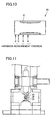
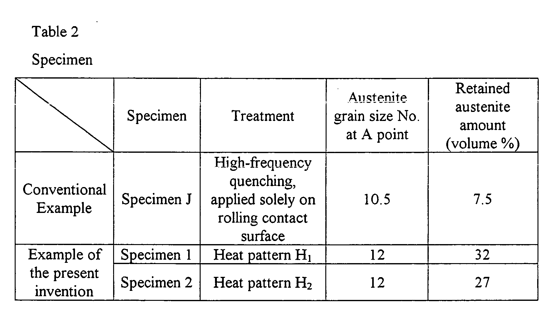
- the surface portion contained 15 to 35 volume % of retained austenite and attained ultrafine austenite grain size of No. 11 or larger. Hardness was measured with respect to this specimen. For comparison, hardness of a specimen J in a conventional example that was subjected solely to high-frequency quenching and not to carbonitriding treatment was also measured. A shape and hardness measurement position for each specimen is as shown in Fig. 10. A measurement result is shown in Table 1. It is noted that a dotted portion in Fig. 10 represents a hardened portion.
- specimens 1 and 2 according to the examples of the present invention attain very high hardness of HV 760 to 805 in surface portions A and B, while they attain hardness of HV 260 to 280 in positions C and D other than the surface portion. Hardness at positions C and D is suitable for caulking.
- surface portions A and B attain hardness of HV 735 to 780, exhibiting variation in a range lower than the former, while hardness at measurement positions C and D is also low, that is, HV 210 to 240.
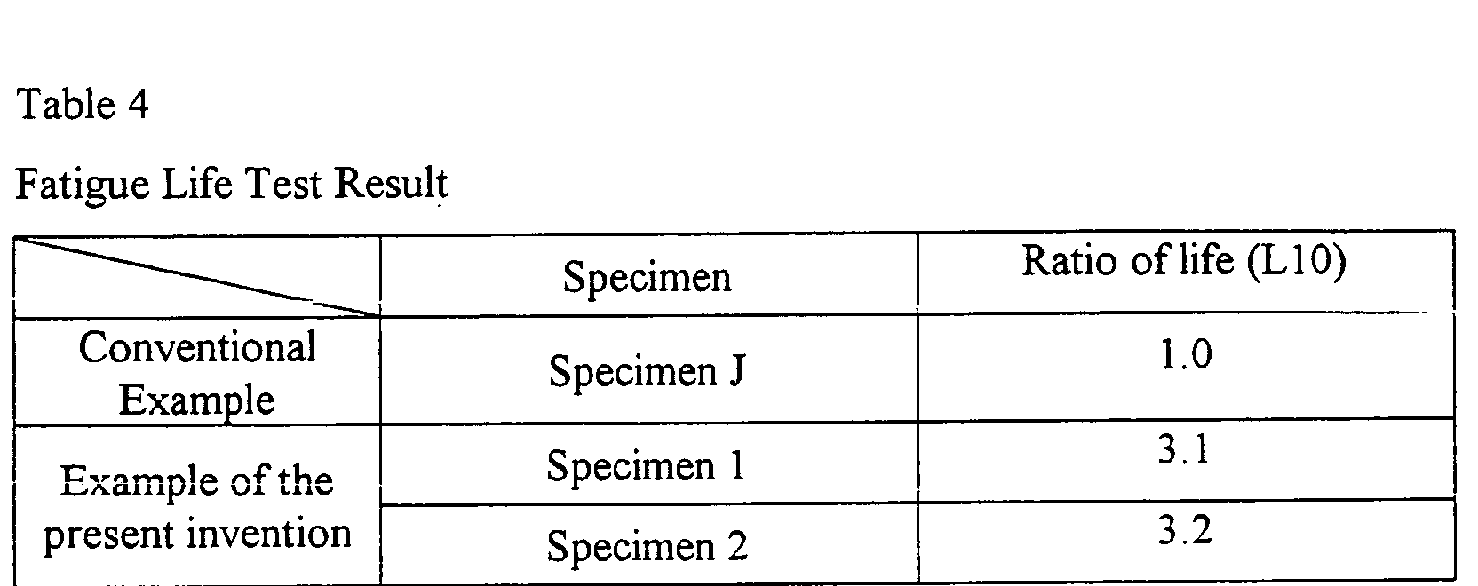
- specimens 1 and 2 according to the example of the present invention attain life three times as long as specimen J in the conventional example. It is considered that specimen J in the conventional example has shorter fatigue life due to its metal structure (austenite grain size, retained austenite amount) because carbonitriding treatment is not performed.
Landscapes
- Engineering & Computer Science (AREA)
- Chemical & Material Sciences (AREA)
- Mechanical Engineering (AREA)
- General Engineering & Computer Science (AREA)
- Metallurgy (AREA)
- Materials Engineering (AREA)
- Organic Chemistry (AREA)
- Thermal Sciences (AREA)
- Physics & Mathematics (AREA)
- Crystallography & Structural Chemistry (AREA)
- Chemical Kinetics & Catalysis (AREA)
- Manufacturing & Machinery (AREA)
- Rolling Contact Bearings (AREA)
- Valve-Gear Or Valve Arrangements (AREA)
- Gears, Cams (AREA)
Abstract
Description

| Fatigue Life Test Conditions | |
| Test rig | Outer ring rotation type life test rig |
| Test sample | Rocker arm bearing assembly product |
| Load (N) | 2200N |
| Outer ring rotation speed | 7000rpm |
| Lubrication | Engine oil 10w-30 |
| Oil temperature | 100°C |
| Life | Separation life |
Claims (17)
- A rolling bearing, comprising:an outer member (4);an inner member (2) located inside said outer member (4); anda rolling element (3) interposed between said outer member and said inner member; whereinat least one member of said outer member (4) and said inner member (2) has a nitrogen enriched layer,in said at least one member, austenite grain size of a surface portion of an area in a rolling contact surface where said rolling element rolls is at least No. 11, andan end portion of that member has hardness of at most HV (Vickers hardness) 300.
- A cam-follower with roller employing the rolling bearing according to claim 1, whereina roller (3) rolling along an inner circumference of an outer-roller (4) is interposed between the outer-roller (4) serving as said outer member and a shaft (2) serving as said inner member,said cam-follower is supported by said shaft, anda portion where said roller (3) rolls is the surface portion of the area in the rolling contact surface.
- A cam (6) abutting on the outer-roller (4) in said cam-follower with roller according to claim 2, whereinsaid cam has a nitrogen enriched layer in the surface portion abutting on said outer member, andaustenite grain size of the surface portion is at least No. 11.
- The cam-follower with roller according to claim 2, whereinsaid shaft (2) has its end portion (2a) subjected to plastic working and is fixed to a roller support member.
- The cam-follower with roller according to claim 4, whereina body of said cam follower (50) is obtained by press-working.
- The rolling bearing according to claim 1, whereinin an area other than the surface portion of the area in said rolling contact surface, microstructure of the area contains ferrite and carbide.
- A cam-follower with roller employing the rolling bearing according to claim 6, whereina roller rolling along an inner circumference of an outer-roller is interposed between the outer-roller serving as said outer member and a shaft serving as said inner member,said cam-follower is supported by said shaft, anda portion where said roller rolls is the surface portion of the area in the rolling contact surface.
- The cam-follower with roller according to claim 7, whereinsaid shaft has its end portion subjected to plastic working and is fixed to a roller support member.
- The cam-follower with roller according to claim 8, whereina body of said cam follower is obtained by press-working.
- The rolling bearing according to claim 1, whereinsaid surface portion of the area in said rolling contact surface is subjected to high-frequency quenching.
- A cam-follower with roller employing the rolling bearing according to claim 10, whereina roller rolling along an inner circumference of an outer-roller is interposed between the outer-roller serving as said outer member and a shaft serving as said inner member,said cam-follower is supported by said shaft, anda portion where said roller rolls is the surface portion of the area in the rolling contact surface.
- The rolling bearing according to claim 1, whereinsaid surface portion of the area in said rolling contact surface has hardness of at least HV653.
- A cam-follower with roller employing the rolling bearing according to claim 12, whereina roller rolling along an inner circumference of an outer-roller is interposed between the outer-roller serving as said outer member and a shaft serving as said inner member,said cam-follower is supported by said shaft, anda portion where said roller rolls is the surface portion of the area in the rolling contact surface of said shaft.
- The rolling bearing according to claim 1, whereinsaid surface portion of the area in said rolling contact surface includes 10 to 50 volume % of retained austenite.
- A cam-follower with roller employing the rolling bearing according to claim 14, whereina roller rolling along an inner circumference of an outer-roller is interposed between the outer-roller serving as said outer member and a shaft serving as said inner member,said cam-follower is supported by said shaft, anda portion where said roller rolls is the surface portion of the area in the rolling contact surface of said shaft.
- The rolling bearing according to claim 1, whereinsaid at least one member is subjected to any one of a treatment of carbonitriding the member at A1 or higher followed by slow cooling down to a point lower than A1 point and then subjecting said surface portion of the area in said rolling contact surface to high-frequency quenching, and a treatment of carbonitriding the member at A1 or higher followed by rapid cooling down to a point lower than A1 point, tempering at the point lower than A1 point, and subjecting said surface portion of the area in said rolling contact surface to high-frequency quenching.
- A cam-follower with roller employing the rolling bearing according to claim 16, whereina roller rolling along an inner circumference of an outer-roller is interposed between the outer-roller serving as said outer member and a shaft serving as said inner member,said cam-follower is supported by said shaft, anda portion where said roller rolls is the surface portion of the area in the rolling contact surface of said shaft.
Applications Claiming Priority (6)
| Application Number | Priority Date | Filing Date | Title |
|---|---|---|---|
| JP2003160720 | 2003-06-05 | ||
| JP2003160720 | 2003-06-05 | ||
| JP2004078794 | 2004-03-18 | ||
| JP2004078794 | 2004-03-18 | ||
| JP2004158046A JP4486411B2 (en) | 2003-06-05 | 2004-05-27 | Cam follower with roller |
| JP2004158046 | 2004-05-27 |
Publications (3)
| Publication Number | Publication Date |
|---|---|
| EP1484517A2 true EP1484517A2 (en) | 2004-12-08 |
| EP1484517A3 EP1484517A3 (en) | 2006-05-31 |
| EP1484517B1 EP1484517B1 (en) | 2008-04-16 |
Family
ID=33162796
Family Applications (1)
| Application Number | Title | Priority Date | Filing Date |
|---|---|---|---|
| EP04013289A Expired - Lifetime EP1484517B1 (en) | 2003-06-05 | 2004-06-04 | Rolling bearing, cam follower with roller, and cam |
Country Status (5)
| Country | Link |
|---|---|
| US (1) | US7603929B2 (en) |
| EP (1) | EP1484517B1 (en) |
| JP (1) | JP4486411B2 (en) |
| CN (1) | CN100504092C (en) |
| DE (1) | DE602004013071T2 (en) |
Cited By (10)
| Publication number | Priority date | Publication date | Assignee | Title |
|---|---|---|---|---|
| EP1701052A3 (en) * | 2005-03-11 | 2008-03-19 | Ntn Corporation | Rolling bearing |
| EP2025886A1 (en) * | 2007-08-10 | 2009-02-18 | Nissan Motor Co., Ltd. | Valvetrain mechanism of engine |
| EP1961925A3 (en) * | 2007-02-23 | 2010-07-28 | JTEKT Corporation | Manufacturing method of rocker arm and rocker arm roller |
| CN101956805A (en) * | 2010-09-27 | 2011-01-26 | 河南柴油机重工有限责任公司 | Process method of arc moulding of rolling wheel by using residual stress truncation method |
| US7882812B2 (en) | 2007-08-10 | 2011-02-08 | Nissan Motor Co., Ltd. | Valvetrain mechanism of engine |
| EP2256307A4 (en) * | 2008-02-19 | 2011-10-05 | Ntn Toyo Bearing Co Ltd | Roller follower, valve gear, apparatus for high-frequency hardening, method of heat-treating shaft member, process for producing shaft, and shaft |
| EP2345822A3 (en) * | 2004-08-02 | 2011-11-23 | NTN Corporation | Rolling bearing for rocker arm |
| CN102776520A (en) * | 2012-08-03 | 2012-11-14 | 西北矿冶研究院 | Heat treatment process for shank of rock drill |
| EP2607636A1 (en) | 2011-12-23 | 2013-06-26 | Aktiebolaget SKF | Mechanical system, injection pump comprising such a mechanical system and method for manufacturing such a mechanical system |
| CN109690141A (en) * | 2016-09-29 | 2019-04-26 | 爱信艾达株式会社 | The manufacturing method of gear ring and gear ring |
Families Citing this family (18)
| Publication number | Priority date | Publication date | Assignee | Title |
|---|---|---|---|---|
| JP2005114147A (en) * | 2003-10-10 | 2005-04-28 | Ntn Corp | Rolling bearing |
| JP2005114144A (en) * | 2003-10-10 | 2005-04-28 | Ntn Corp | Rolling bearing |
| JP2005114148A (en) * | 2003-10-10 | 2005-04-28 | Ntn Corp | Rolling bearing |
| JP4737954B2 (en) * | 2004-08-02 | 2011-08-03 | Ntn株式会社 | Roller bearing for rocker arm |
| JP4566036B2 (en) * | 2005-03-11 | 2010-10-20 | Ntn株式会社 | Rolling bearing |
| JP2007169673A (en) * | 2005-12-19 | 2007-07-05 | Nsk Ltd | Steel heat treatment method, rolling support device manufacturing method for rolling support device, rolling support device |
| JP2007177288A (en) * | 2005-12-28 | 2007-07-12 | Nsk Ltd | Rolling support device and method of manufacturing rolling member thereof |
| JP2008020003A (en) * | 2006-07-13 | 2008-01-31 | Ntn Corp | Process for producing track member and valve gear, and track member |
| EP2085627B1 (en) * | 2006-10-26 | 2013-07-31 | NTN Corporation | Outer ring for rocking bearing, retainer for rocking bearing, rocking bearing, and air disc brake |
| JP5388264B2 (en) * | 2007-12-14 | 2014-01-15 | Ntn株式会社 | Manufacturing method of rolling shaft |
| JP5307477B2 (en) * | 2008-08-21 | 2013-10-02 | Ntn株式会社 | Cam follower and cam follower device for rocker arm |
| DE102010019950A1 (en) * | 2010-05-08 | 2011-11-10 | Mahle International Gmbh | Bearing arrangement has component that is supported in housing, where bearing pin clamps bearing bore of component and aligned retaining hole of housing |
| CN103732946B (en) * | 2011-07-20 | 2016-08-17 | Ntn株式会社 | Chain guiding piece and chain and sprocket driving device |
| JP2013024365A (en) * | 2011-07-25 | 2013-02-04 | Ntn Corp | Chain guide and chain transmission device |
| US20150198230A1 (en) * | 2014-01-13 | 2015-07-16 | Electro-Motive Diesel Inc. | Cam follower assembly having swaged bushing |
| DE102014206660A1 (en) * | 2014-04-07 | 2015-10-08 | Schaeffler Technologies AG & Co. KG | stroke-transmission component |
| DE102019102289B3 (en) * | 2019-01-30 | 2020-03-05 | Schaeffler Technologies AG & Co. KG | Roller plunger for a fuel pump |
| DE102020201038A1 (en) * | 2020-01-29 | 2021-07-29 | Mahle International Gmbh | Camshaft arrangement |
Family Cites Families (26)
| Publication number | Priority date | Publication date | Assignee | Title |
|---|---|---|---|---|
| JPH0615811B2 (en) | 1985-07-03 | 1994-03-02 | 本田技研工業株式会社 | Cam follower with roller |
| JPS63185917A (en) | 1987-01-26 | 1988-08-01 | Tsumoru Murakami | Trichogenous solution |
| JP2743488B2 (en) * | 1989-06-29 | 1998-04-22 | 日本精工株式会社 | Cam follower for engine valve train |
| JPH0680287B2 (en) * | 1991-02-15 | 1994-10-12 | 本田技研工業株式会社 | Cam follower with roller |
| JP2974505B2 (en) | 1992-06-30 | 1999-11-10 | キヤノン株式会社 | Ink jet recording head and recording apparatus equipped with the same |
| JPH05239550A (en) | 1992-02-27 | 1993-09-17 | Ntn Corp | Rolling parts |
| JPH05321618A (en) | 1992-05-25 | 1993-12-07 | Komatsu Ltd | Variable valve timing device |
| JP3269576B2 (en) | 1992-09-03 | 2002-03-25 | 昌志 小林 | Roll winding end bonding device |
| JPH1030150A (en) | 1996-07-19 | 1998-02-03 | Nippon Seiko Kk | Rolling bearing |
| JPH1047334A (en) | 1996-08-02 | 1998-02-17 | Nippon Seiko Kk | Rolling sliding parts |
| JP3857366B2 (en) | 1996-09-30 | 2006-12-13 | 株式会社ジェイテクト | Bearing device |
| JPH10110720A (en) | 1996-10-08 | 1998-04-28 | Mitsubishi Motors Corp | Bearing structure |
| JP3909902B2 (en) | 1996-12-17 | 2007-04-25 | 株式会社小松製作所 | Steel parts for high surface pressure resistance and method for producing the same |
| JP3591236B2 (en) | 1997-09-04 | 2004-11-17 | 日本精工株式会社 | Rolling bearing |
| US6224688B1 (en) * | 1997-08-18 | 2001-05-01 | Nsk Ltd. | Rolling bearing |
| JPH11101247A (en) | 1997-09-29 | 1999-04-13 | Ntn Corp | Rolling bearing part |
| JP4100751B2 (en) * | 1998-01-30 | 2008-06-11 | 株式会社小松製作所 | Rolling member and manufacturing method thereof |
| JP2000038907A (en) | 1998-07-21 | 2000-02-08 | Nippon Seiko Kk | Cam follower device for engine valve train |
| JP2000038906A (en) | 1998-07-21 | 2000-02-08 | Nippon Seiko Kk | Cam follower device for engine valve train |
| JP3869138B2 (en) | 1999-01-13 | 2007-01-17 | 株式会社ジェイテクト | Rolling and sliding parts |
| JP2001280348A (en) * | 2000-03-28 | 2001-10-10 | Nsk Ltd | Rolling bearing |
| JP3761766B2 (en) | 2000-05-29 | 2006-03-29 | 株式会社ジェイテクト | Cam follower |
| JP3869192B2 (en) | 2000-07-17 | 2007-01-17 | 株式会社ジェイテクト | Rolling and sliding parts |
| JP2002194438A (en) | 2000-12-22 | 2002-07-10 | Nsk Ltd | Rolling bearing |
| US7438477B2 (en) * | 2001-11-29 | 2008-10-21 | Ntn Corporation | Bearing part, heat treatment method thereof, and rolling bearing |
| US7334943B2 (en) * | 2003-02-28 | 2008-02-26 | Ntn Corporation | Differential support structure, differential's component, method of manufacturing differential support structure, and method of manufacturing differential's component |
-
2004
- 2004-05-27 JP JP2004158046A patent/JP4486411B2/en not_active Expired - Lifetime
- 2004-06-03 US US10/859,120 patent/US7603929B2/en active Active
- 2004-06-04 DE DE602004013071T patent/DE602004013071T2/en not_active Expired - Lifetime
- 2004-06-04 EP EP04013289A patent/EP1484517B1/en not_active Expired - Lifetime
- 2004-06-07 CN CNB200410048844XA patent/CN100504092C/en not_active Expired - Lifetime
Cited By (13)
| Publication number | Priority date | Publication date | Assignee | Title |
|---|---|---|---|---|
| EP2345822A3 (en) * | 2004-08-02 | 2011-11-23 | NTN Corporation | Rolling bearing for rocker arm |
| EP1701052A3 (en) * | 2005-03-11 | 2008-03-19 | Ntn Corporation | Rolling bearing |
| US7703984B2 (en) | 2005-03-11 | 2010-04-27 | Ntn Corporation | Rolling bearing |
| EP1961925A3 (en) * | 2007-02-23 | 2010-07-28 | JTEKT Corporation | Manufacturing method of rocker arm and rocker arm roller |
| EP2025886A1 (en) * | 2007-08-10 | 2009-02-18 | Nissan Motor Co., Ltd. | Valvetrain mechanism of engine |
| US7882812B2 (en) | 2007-08-10 | 2011-02-08 | Nissan Motor Co., Ltd. | Valvetrain mechanism of engine |
| EP2256307A4 (en) * | 2008-02-19 | 2011-10-05 | Ntn Toyo Bearing Co Ltd | Roller follower, valve gear, apparatus for high-frequency hardening, method of heat-treating shaft member, process for producing shaft, and shaft |
| US8844489B2 (en) | 2008-02-19 | 2014-09-30 | Ntn Corporation | Roller follower, valve train, induction hardening apparatus, method of heat treatment of shaft member, method of manufacturing shaft, and shaft |
| CN101956805A (en) * | 2010-09-27 | 2011-01-26 | 河南柴油机重工有限责任公司 | Process method of arc moulding of rolling wheel by using residual stress truncation method |
| EP2607636A1 (en) | 2011-12-23 | 2013-06-26 | Aktiebolaget SKF | Mechanical system, injection pump comprising such a mechanical system and method for manufacturing such a mechanical system |
| CN102776520A (en) * | 2012-08-03 | 2012-11-14 | 西北矿冶研究院 | Heat treatment process for shank of rock drill |
| CN102776520B (en) * | 2012-08-03 | 2015-01-14 | 西北矿冶研究院 | Heat treatment process for shank of rock drill |
| CN109690141A (en) * | 2016-09-29 | 2019-04-26 | 爱信艾达株式会社 | The manufacturing method of gear ring and gear ring |
Also Published As
| Publication number | Publication date |
|---|---|
| JP4486411B2 (en) | 2010-06-23 |
| EP1484517B1 (en) | 2008-04-16 |
| DE602004013071T2 (en) | 2009-06-25 |
| JP2005299914A (en) | 2005-10-27 |
| EP1484517A3 (en) | 2006-05-31 |
| CN1573148A (en) | 2005-02-02 |
| CN100504092C (en) | 2009-06-24 |
| DE602004013071D1 (en) | 2008-05-29 |
| US7603929B2 (en) | 2009-10-20 |
| US20040247216A1 (en) | 2004-12-09 |
Similar Documents
| Publication | Publication Date | Title |
|---|---|---|
| EP1484517B1 (en) | Rolling bearing, cam follower with roller, and cam | |
| US7614374B2 (en) | Rolling bearing for rocker arm | |
| US7490583B2 (en) | Full-type rolling bearing and roller cam follower for engine | |
| US5427457A (en) | Rolling bearing | |
| JPH10176219A (en) | Steel parts for high surface pressure resistance and manufacturing method thereof | |
| JP4566036B2 (en) | Rolling bearing | |
| JPH0579742B2 (en) | ||
| JP3990254B2 (en) | Full-roller type rolling bearing | |
| US7703984B2 (en) | Rolling bearing | |
| CN100516572C (en) | Rolling bearings for rocker arms | |
| JP4897060B2 (en) | Manufacturing method of roller shaft | |
| JP4208797B2 (en) | Rolling bearings used for rocker arms | |
| JP2008063603A (en) | Method for manufacturing track member, method for manufacturing valve device, and track member | |
| JP2008019482A (en) | Method for manufacturing orbital member, method for manufacturing dynamic valve, and orbital member | |
| JP2004060807A (en) | Rolling bearing | |
| JP4368765B2 (en) | Roller bearing for rocker arm | |
| JP2008064159A (en) | Method of manufacturing track member, method of manufacturing valve gear, and track member | |
| JP2005291342A (en) | Needle roller bearing | |
| JP2006329268A (en) | Rolling bearing for planetary gear mechanism | |
| JP4886007B2 (en) | Roller bearing for rocker arm | |
| JP2004183589A (en) | Cam follower device |
Legal Events
| Date | Code | Title | Description |
|---|---|---|---|
| PUAI | Public reference made under article 153(3) epc to a published international application that has entered the european phase |
Free format text: ORIGINAL CODE: 0009012 |
|
| AK | Designated contracting states |
Kind code of ref document: A2 Designated state(s): AT BE BG CH CY CZ DE DK EE ES FI FR GB GR HU IE IT LI LU MC NL PL PT RO SE SI SK TR |
|
| AX | Request for extension of the european patent |
Extension state: AL HR LT LV MK |
|
| PUAL | Search report despatched |
Free format text: ORIGINAL CODE: 0009013 |
|
| AK | Designated contracting states |
Kind code of ref document: A3 Designated state(s): AT BE BG CH CY CZ DE DK EE ES FI FR GB GR HU IE IT LI LU MC NL PL PT RO SE SI SK TR |
|
| AX | Request for extension of the european patent |
Extension state: AL HR LT LV MK |
|
| RIC1 | Information provided on ipc code assigned before grant |
Ipc: F16C 33/62 20060101ALI20060407BHEP Ipc: C21D 9/40 20060101ALI20060407BHEP Ipc: C23C 8/32 20060101AFI20060407BHEP Ipc: F16C 33/64 20060101ALI20060407BHEP Ipc: F16H 53/06 20060101ALI20060407BHEP Ipc: F01L 1/14 20060101ALI20060407BHEP Ipc: F01L 1/18 20060101ALI20060407BHEP |
|
| 17P | Request for examination filed |
Effective date: 20061026 |
|
| AKX | Designation fees paid |
Designated state(s): DE FR IT |
|
| 17Q | First examination report despatched |
Effective date: 20070312 |
|
| GRAP | Despatch of communication of intention to grant a patent |
Free format text: ORIGINAL CODE: EPIDOSNIGR1 |
|
| GRAS | Grant fee paid |
Free format text: ORIGINAL CODE: EPIDOSNIGR3 |
|
| GRAA | (expected) grant |
Free format text: ORIGINAL CODE: 0009210 |
|
| AK | Designated contracting states |
Kind code of ref document: B1 Designated state(s): DE FR IT |
|
| REF | Corresponds to: |
Ref document number: 602004013071 Country of ref document: DE Date of ref document: 20080529 Kind code of ref document: P |
|
| ET | Fr: translation filed | ||
| PLBE | No opposition filed within time limit |
Free format text: ORIGINAL CODE: 0009261 |
|
| STAA | Information on the status of an ep patent application or granted ep patent |
Free format text: STATUS: NO OPPOSITION FILED WITHIN TIME LIMIT |
|
| 26N | No opposition filed |
Effective date: 20090119 |
|
| REG | Reference to a national code |
Ref country code: FR Ref legal event code: PLFP Year of fee payment: 12 |
|
| REG | Reference to a national code |
Ref country code: FR Ref legal event code: PLFP Year of fee payment: 13 |
|
| REG | Reference to a national code |
Ref country code: FR Ref legal event code: PLFP Year of fee payment: 14 |
|
| REG | Reference to a national code |
Ref country code: FR Ref legal event code: PLFP Year of fee payment: 15 |
|
| PGFP | Annual fee paid to national office [announced via postgrant information from national office to epo] |
Ref country code: IT Payment date: 20230510 Year of fee payment: 20 Ref country code: FR Payment date: 20230510 Year of fee payment: 20 Ref country code: DE Payment date: 20230502 Year of fee payment: 20 |
|
| REG | Reference to a national code |
Ref country code: DE Ref legal event code: R071 Ref document number: 602004013071 Country of ref document: DE |