EP1486616A1 - Wire type excavating accuracy control device of soil improving machine - Google Patents
Wire type excavating accuracy control device of soil improving machine Download PDFInfo
- Publication number
- EP1486616A1 EP1486616A1 EP03703220A EP03703220A EP1486616A1 EP 1486616 A1 EP1486616 A1 EP 1486616A1 EP 03703220 A EP03703220 A EP 03703220A EP 03703220 A EP03703220 A EP 03703220A EP 1486616 A1 EP1486616 A1 EP 1486616A1
- Authority
- EP
- European Patent Office
- Prior art keywords
- excavating
- control device
- shaft
- agitating blade
- tip position
- Prior art date
- Legal status (The legal status is an assumption and is not a legal conclusion. Google has not performed a legal analysis and makes no representation as to the accuracy of the status listed.)
- Withdrawn
Links
Images


Classifications
-
- E—FIXED CONSTRUCTIONS
- E02—HYDRAULIC ENGINEERING; FOUNDATIONS; SOIL SHIFTING
- E02F—DREDGING; SOIL-SHIFTING
- E02F3/00—Dredgers; Soil-shifting machines
- E02F3/04—Dredgers; Soil-shifting machines mechanically-driven
- E02F3/06—Dredgers; Soil-shifting machines mechanically-driven with digging screws
-
- E—FIXED CONSTRUCTIONS
- E02—HYDRAULIC ENGINEERING; FOUNDATIONS; SOIL SHIFTING
- E02D—FOUNDATIONS; EXCAVATIONS; EMBANKMENTS; UNDERGROUND OR UNDERWATER STRUCTURES
- E02D13/00—Accessories for placing or removing piles or bulkheads, e.g. noise attenuating chambers
- E02D13/06—Accessories for placing or removing piles or bulkheads, e.g. noise attenuating chambers for observation while placing
-
- E—FIXED CONSTRUCTIONS
- E02—HYDRAULIC ENGINEERING; FOUNDATIONS; SOIL SHIFTING
- E02D—FOUNDATIONS; EXCAVATIONS; EMBANKMENTS; UNDERGROUND OR UNDERWATER STRUCTURES
- E02D3/00—Improving or preserving soil or rock, e.g. preserving permafrost soil
- E02D3/12—Consolidating by placing solidifying or pore-filling substances in the soil
- E02D3/126—Consolidating by placing solidifying or pore-filling substances in the soil and mixing by rotating blades
-
- E—FIXED CONSTRUCTIONS
- E02—HYDRAULIC ENGINEERING; FOUNDATIONS; SOIL SHIFTING
- E02F—DREDGING; SOIL-SHIFTING
- E02F3/00—Dredgers; Soil-shifting machines
- E02F3/04—Dredgers; Soil-shifting machines mechanically-driven
- E02F3/08—Dredgers; Soil-shifting machines mechanically-driven with digging elements on an endless chain
- E02F3/12—Component parts, e.g. bucket troughs
- E02F3/16—Safety or control devices
-
- E—FIXED CONSTRUCTIONS
- E02—HYDRAULIC ENGINEERING; FOUNDATIONS; SOIL SHIFTING
- E02F—DREDGING; SOIL-SHIFTING
- E02F3/00—Dredgers; Soil-shifting machines
- E02F3/04—Dredgers; Soil-shifting machines mechanically-driven
- E02F3/18—Dredgers; Soil-shifting machines mechanically-driven with digging wheels turning round an axis, e.g. bucket-type wheels
- E02F3/22—Component parts
- E02F3/26—Safety or control devices
Definitions
- the present invention relates to a technical field of a wire type excavating accuracy control device for accurately assessing the specified lap amounts between piles in soil columns by forcibly correcting or controlling the tip position of an excavating and agitating blade shaft of a soil improving machine used for constructing lapped type piles in soil columns, in real time, at the construction site for purposes of building earth-retaining walls, foundation work for civil engineering and construction, construction for preventing the liquefaction of soil, building cut-off walls and the like.
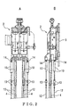
- FIG. 1 Various kinds of soil improving construction have conventionally been performed using a soil improving machine, as shown in FIG. 1, for example.
- a soil improving machine according to this machine, by means of a digging drive 2 that is suspended on the top sheave 5 of a leader 1 that is moved vertically along a rail 3, a drive shaft 4 suspended directly thereunder is driven by rotation and propelled perpendicularly downward at the same time.
- the drive shaft 4 has a lower end connected to an excavating and agitating blade shaft 6 provided with a tip-end cutter 7 and a plurality of agitating blades 8 above and below.
- control method described in document (1) is configured to control the movement amount of the wires by using a hydraulic control device
- a critical control targeted value is determined by an indirect measurement method based on the movement amount of the wires.
- the construction control method stated in document (2) is innovative in that the three-dimensional gyro sensor is employed, and that the actual lap length is understood and controlled in real time by means of the global positioning system for measuring the self-location through the use of the GPS.
- the position correction is carried out simply by reversing the tip-end excavation cutter. Consequently, the invention has the drawback of being difficult with respect to providing a prompt and reliable response.
- the soil improving construction method described in document (3) has greater possibility of a prompt and reliable response, compared to the above-described two inventions, in that the measurement is carried out by a measurement means using a three-dimensional gyro sensor, and that the joint portion between the drive shaft and the excavating and agitating blade shaft of the soil improving machine is formed into an adjustable joint capable of transmitting the running torque to enable the position correction of the excavating and agitating blade shaft by using at least three hydraulic cylinders. Because of the configuration in which delicate machine parts (adjustable joint, hydraulic cylinders, etc.) are propelled deep into the excavation soil, however, there are problems securing durability, maintenance and inspection.
- the excavating accuracy control method disclosed in document (5) is noteworthy in that it is a wire type control method. However, the relevance to the technology of position measurement of the excavating and agitating blade shaft is obscure.
- An object of the present invention consists in providing a wire type excavating accuracy control device for a soil improving machine, which incorporates the technology for detecting the tip position of the excavating and agitating blade shaft by means of a three-dimensional gyro sensor described in document (2) while making use of the advantages of a wire type excavating accuracy control method, thereby being capable of detecting a position (locus) of an improving pile previously constructed and subsequently a tip position of an excavating shaft of an improving pile to be lapped thereover, in real time, and in the event that the positions show a tendency to deviate from planned positions during construction, performing immediate directional correction of the tip position under precise and responsive control, implementing real-time position correction at the construction, securing required or appropriate lapped amounts and controlling plumbing accuracy.
- Another object of the present invention is to provide a wire type excavating accuracy control device for a soil improving machine that makes it possible to accurately secure specified lapped amounts between piles in soil columns without difficulty, to carry out efficient construction with lap length required by design, and to perform construction with proper pitch of soil improving piles, to thereby realize efficient and economical soil improving construction.
- a wire type excavating accuracy control device in a soil improving machine consists of a plurality of wires or the like 12 arranged around a drive shaft 4 and coupled between hydraulic cylinders 10 suspended under a digging drive 2 for rotating-driving the drive shaft 4 of the soil improving machine to propel the drive shaft 4 along a leader 1 perpendicularly downward and a bearing member 11 disposed in a portion directly above an excavating and agitating blade shaft 6 connected to a lower end of the drive shaft 4, and corrects and controls the tip position of the excavating and agitating blade shaft 6 by pulling the wires or the like 12 individually by means of the hydraulic cylinders 10.
- the wire type excavating accuracy control device comprises a three-dimensional gyro sensor device that is located near the bearing member 11 and detects the tip position of the excavating and agitating blade shaft 6, a construction control device 22 into which measurement signals for the tip position of the excavating and agitating blade shaft 6, measured by the three-dimensional gyro sensor device, are inputted, and a hydraulic control circuit of the hydraulic cylinder 10 controlled by control signals calculated and processed by the construction control device 22 on the basis of the measurement signals, and is characterized in that the hydraulic cylinders 10 are individually controlled to pull the respective wires or the like 12, to thereby forcibly correct and control the tip position of the excavating and agitating blade shaft 6.
- the invention claimed in claim 2 is the wire type excavating accuracy control device of a soil improving machine according to claim 1, characterized in that the drive shaft 4 is configured as a multi-connecting shaft obtained by successively jointing a plurality of unit shafts, and that a curve is generated in the drive shaft 4 through the use of allowance of a shaft coupling 40 of each joint portion, to thereby make it possible to forcibly correct and control the tip position of the excavating and agitating blade shaft 6.
- the invention claimed in claim 3 is the wire type excavating accuracy control device of a soil improving machine according to either one of claims 1 and 2, characterized in that the bearing member 11 for maintaining constant center distance between drive shafts 4 in a multishaft soil improving machine using a plurality of drive shafts 4 is configured in a pin-joint structure in which bearings for respective drive shafts 4 are roller bearings 11a and are movably jointed with a horizontal pin 11d so as to allow deformation between the bearings in between the adjacent drive shafts 4, and that the plurality of wires or the like 12 that are symmetrically provided to each bearing 11a have lower ends connected to respective brackets 15 protruding from the bearing member 11 in a lateral direction.
- the invention claimed in claim 4 is the wire type excavating accuracy control device of a soil improving machine according to claim 1, characterized in that the hydraulic control circuit of the hydraulic cylinder 10 comprises a high pressure control circuit 30 and a low pressure control circuit 31 juxtaposed with each other, supplies high-pressure oil from the high pressure control circuit 30 to the hydraulic cylinder 10 to pull the wires or the like 12, and supplies low-pressure oil from the low pressure control circuit 31 to pull in the slack of the wires or the like 12.
- a soil improving machine of FIG. 1 comprises a wire type excavating accuracy control device, including a plurality of wires 12 (PC steel rods, PC steel wires or the like may be utilized instead, and hereinafter, they are generically referred to as "wires or the like"), arranged around a drive shaft 4 and coupled between hydraulic cylinders 10 suspended under a digging drive 2 for rotating-driving the drive shaft 4 to propel the drive shaft 4 along a rail 3 of a leader 1 perpendicularly downward, and a bearing member 11 disposed in a portion directly above an excavating and agitating blade shaft 6 connected to a lower end of the drive shaft 4, to thereby forcibly correct and control a tip position of the excavating and agitating blade shaft 6 by pulling the wires 12 individually by means of the hydraulic cylinders 10.
- wires 12 PC steel rods, PC steel wires or the like
- FIGS. 2A and 2B showing a digging drive 2 on an enlarged scale
- this is an embodiment of a two-axis soil improving machine.
- a locational relation between two excavating and agitating blade shafts 6, 6 connected to lower ends of two drive shafts 4, 4 and the plurality of wires 12 ... is as exemplified in FIGS. 3 and 4 showing an arrangement in which a total of 6 wires 12 ... encircle the two drive shafts 4, 4.
- FIG. 2 shows a configuration in which upper ends of the six wires 12 ... are connected to output shafts of the hydraulic cylinders 10 through coupling members 13 of a pin-joint type so as to link one wire with one cylinder.
- the body of each hydraulic cylinder 10 has an upper end portion that is freely coupled to a bracket prepared in a lower base portion of the digging drive 2 also through a pin joint 14.
- the six wires 12 ... have lower ends joined to respective brackets 15 protruding from the bearing member 11 in a lateral direction such that length thereof can be adjusted by respective screw-operated coupling members 16, as illustrated in FIG. 3 on an enlarged scale.
- the coupling members 16 are covered with respective protection covers 17 for fear that they will be defaced by earth and sand.
- the length of each wire 12 is adjusted such that the bearing member 11 retains a level posture in a state where the hydraulic cylinders 10 are beforehand extended at maximum stroke.
- roller bearings 11a which rotatably support the drive shafts 4 with low friction.
- the roller bearings 11a possesses an advantage of having sufficient rigidity to forcibly correct the tip position of the excavating and agitating blade shaft 6 by pulling the bearing member 11 through the wire control.
- a concrete configuration of the roller bearings 11a, which is preferably employed, is one in which the drive shafts 4 are rotatably supported by roller bearings of an angular type, as shown in FIG. 5 of Unexamined Japanese Patent Publication No. 2001-234527, or the like.
- the two roller bearings 11a are movably constructed as a pin-joint structure in which brackets 11b extending in parallel from outer surfaces thereof in a lateral direction and both ends of a hinge member 11c located at a middle position are put together, thereby being coupled to each other by piercing two pins 11d therethrough in the lateral direction.
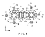
- the lower ends of the six wires 12 ... are, as illustrated in FIG. 4, joined to their respective brackets 15 arranged at regular intervals in positions located in three right-angled directions, the positions being included in a semicircle that is approximately half of the outer side of each of the two roller bearings 11a, 11a, so that a moment operates with lateral arms protruded, (the aforementioned is the invention claimed in claim 3).
- the tip positions of not only the two drive shafts 4, 4, but the two excavating and agitating blade shafts 6, 6 as well, can be forcibly and accurately corrected and controlled without difficulty in either an anteroposterior direction (the Y direction in FIG. 4) or lateral direction (the X direction in FIG. 4).
- a three-dimensional gyro sensor device is installed in a sensor case 20 located near the bearing member 11, as more specifically shown in FIG. 3, halfway between the two drive shafts 4, 4, by being fixed onto the outer surface of the right bearing 11a, facing into the drawing, the device being composed by combining a clinometer of X, Y two-dimensional directions and a gyro sensor, as disclosed in, for example, Japanese Patent No. 3156049, although a detailed illustration is omitted.
- the tip position of the excavating and agitating blade shaft 6 is accurately detected in real time. Furthermore, a locus and horizontal cross sectional shape of the constructed piles in soil columns are stored as data. Measurement signals according to the three-dimensional gyro sensor device are transmitted to an above-ground construction control device 22 (FIG. 5) through signal wires in a signal wire protection pipe 21 connected to the sensor case 20.
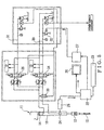
- FIG. 5 shows a hydraulic control circuit for automatically controlling the hydraulic cylinder 10 in real time, based on a measurement value of the three-dimensional gyro sensor device.
- the circuit has a configuration in which a high-pressure control circuit 30 and a low-pressure control circuit 31 juxtaposed with each other are provided to one hydraulic cylinder 10, and the wire 12 is pulled by way of the high-pressure control circuit 30.
- the construction control device 22 which is a common personal computer
- the signals 23 are subjected to comparative calculation with pressure signals 25 inputted from a pressure converter 24 that is attached to each hydraulic cylinder 10.
- the result of the comparative calculation is sent to an operating panel 27 for a hydraulic cylinder, and is simultaneously displayed on the screen of a monitor 26 for an operator in real time.
- control signals with respect to the high pressure control circuits 30 and the low pressure control circuits 31 of the six hydraulic cylinders 10 ... are generated and transmitted.
- an electromagnetic relief valve 32, a shut-off valve 33 and an electromagnetic switch valve 34 of the high pressure control circuit 30 and an electromagnetic switch valve 35 of the low pressure control circuit 31 are each controlled.
- the high pressure control circuit 30 is opened up to supply high-pressure oil into a piston lower chamber of the hydraulic cylinder 10, to thereby cause contraction, in a state where the shut-off valve 33 is free.
- the shut-off valve 33 is closed to maintain a constant stroke of the hydraulic cylinder 10 even if an external force is applied thereto.
- the low pressure control circuit 31 is opened up with the shut-off valve 33 made free to supply low-pressure oil into the piston lower chamber of the hydraulic cylinder 10, to thereby retain a state of tension by pulling gently so as not to slacken the wire 12, (the invention claimed in claim 4).
- the position correction of the tip positions of not only the two drive shafts 4, 4, but the two excavating and agitating blade shafts 6, 6, is controlled by pulling the wires 12 individually by means of the hydraulic cylinders 10.
- adjustment of the pulling force (amount of hydraulic pressure supplied to the hydraulic cylinders 10) varies depending on conditions, such as texture and property of excavation soil, greatness of lap length of the piles in soil columns, etc. Therefore, preferably, test construction is first carried out to collect information necessary for practice, and the construction is carried out after determining the amount of the controllable pulling force and that of the hydraulic pressure, based on such information.
- the pin-joint structure in which the two roller bearings 11a, 11a as bearing components of the bearing member 11 are coupled with the pins 11d, makes it possible to carry out the position correction with high response without generating useless resistance.
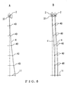
- the drive shaft 4 of the soil improving machine is constructed as a multi-connecting shaft obtained by continuously joining a plurality of unit shafts to one another with the shaft couplings 40 as illustrated in FIGS. 6A and 6B.
- a curve is smoothly made in the drive shaft 4 as far as the location of the bearing member 11, to thereby make it possible to forcibly correct the tip position of the excavating and agitating blade shaft 6, (the invention claimed in claim 2).
- unit shafts of the excavating shaft 4 including general shafts with a length falling in a range of from 5 m to 10 m, and adjustment shafts from 1 m to 4 m. Allowance of the shaft coupling 40 is usually about 2.6 ⁇ 10 -2 rad. when the coupling is brand-new, and gradually grows according to the frequency of usage. For this reason, if the number of the shaft couplings 40 is properly designed, the flexible drive shaft 4 can be obtained without difficulty, and the position correction then becomes simple, thereby being much more advantageous than a single-operating drive shaft in terms of control. There is no fear of adverse effects of such allowance since applying a proper pulling force to the drive shaft 4 in a balanced manner using the wire 12 has the effect of improving rigidity of the drive shaft 4.
- a fixing point of the drive shaft 4 is a lower steady brace 37. Therefore, it is desirable that the lower steady brace 37 be embodied in a configuration in which a roller type guide mechanism using a roller for rotatably supporting the drive shaft 4 is employed, for instance as illustrated in FIG. 2A of Unexamined Japanese Patent Publication No. 2001-234527, for example.
- a middle steady brace 38 is also configured in the same manner.
- the wire type excavating accuracy control device of a soil improving machine is capable of measuring the tip position of the excavating and agitating blade shaft by using a three-dimensional gyro sensor device, detecting the locus of the improving pile previously constructed and subsequently the tip position of the excavating shaft of the improving pile to be lapped over, in real time, to make comparative calculation, and in the event the tendency to deviate from the planned position is observed, capable of accurately making immediate directional correction of the tip position under highly responsive control, thereby carrying out control of plumbing accuracy for securing the exact lapped amounts required at the construction site.
- the present invention makes it possible to perform easily construction in which the specified lapped amounts between piles in soil columns are secured with accuracy. This enables efficient construction with the lap length required by design. As a result, it is possible to make the pitch of the soil improving piles proper, to thereby perform efficient and economical soil improving construction.
Landscapes
- Engineering & Computer Science (AREA)
- Structural Engineering (AREA)
- General Engineering & Computer Science (AREA)
- Mining & Mineral Resources (AREA)
- Civil Engineering (AREA)
- Life Sciences & Earth Sciences (AREA)
- Mechanical Engineering (AREA)
- Paleontology (AREA)
- General Life Sciences & Earth Sciences (AREA)
- Agronomy & Crop Science (AREA)
- Environmental & Geological Engineering (AREA)
- Soil Sciences (AREA)
- Consolidation Of Soil By Introduction Of Solidifying Substances Into Soil (AREA)
Abstract
Description
Claims (4)
- A wire type excavating accuracy control device of a soil improving machine consisting of a plurality of wires or the like (12) arranged around a drive shaft (4) and coupled between hydraulic cylinders (10) suspended under a digging drive (2) for rotating-driving said drive shaft (4) of said soil improving machine to propel said drive shaft (4) along a leader (1) perpendicularly downward and a bearing member (11) disposed in a portion directly above an excavating and agitating blade shaft (6) connected to a lower end of said drive shaft (4), and correcting and controlling a tip position of said excavating and agitating blade shaft (6) by pulling said wires or the like (12) individually by means of said hydraulic cylinders (10), said wire type excavating accuracy control device comprising:a three-dimensional gyro sensor device that is located near said bearing member (11) and detects said tip position of said excavating and agitating blade shaft (6);a construction control device (22) into which measurement signals (23) for said tip position of said excavating and agitating blade shaft (6), measured by said three-dimensional gyro sensor device, are inputted; anda hydraulic control circuit of said hydraulic cylinder (10) controlled by control signals calculated and processed by said construction control device (22) based on said measurement signals (23), wherein:said applicable hydraulic cylinders (10) are individually controlled to pull said respective wires or the like (12), thereby forcibly to correct and control said tip position of said excavating and agitating blade shaft (6).
- The wire type excavating accuracy control device of a soil improving machine according to claim 1, wherein said drive shaft (4) is configured as a multi-connecting shaft obtained by successively joining a plurality of unit shafts to one another, and wherein a curve is generated in said drive shaft (4) through use of allowance of a shaft coupling (40) of each joint portion, thereby making it possible to correct and control forcibly said tip position of said excavating and agitating blade shaft (6).
- The wire type excavating accuracy control device of a soil improving machine according to either one of claims 1 and 2, wherein said bearing member (11) for maintaining constant center distance between drive shafts (4) in a multishaft soil improving machine using a plurality of drive shafts (4) is configured in a pin-joint structure in which bearings for respective drive shafts (4) are roller bearings (11a) and are movably joined with a horizontal pin (11d) so as to allow deformation between the bearings in between said adjacent drive shafts (4), and wherein said plurality of wires or the like (12) that are symmetrically provided to each of said bearings (11a) have lower ends connected to respective brackets (15) protruding from said bearing member (11) in a lateral direction.
- The wire type excavating accuracy control device of a soil improving machine according to claim 1, wherein said hydraulic control circuit of said hydraulic cylinder (10) comprises a high pressure control circuit (30) and a low pressure control circuit (31) juxtaposed with each other, supplies high-pressure oil of said high pressure control circuit (30) to said hydraulic cylinder (10) to pull said wires or the like (12), and supplies low-pressure oil of said low pressure control circuit (31) to pull in the slack of said wires or the like (12).
Applications Claiming Priority (3)
| Application Number | Priority Date | Filing Date | Title |
|---|---|---|---|
| JP2002052189A JP3747281B2 (en) | 2002-02-27 | 2002-02-27 | Wire excavation accuracy controller for ground improvement processing machine |
| JP2002052189 | 2002-02-27 | ||
| PCT/JP2003/001256 WO2003072882A1 (en) | 2002-02-27 | 2003-02-06 | Wire type excavating accuracy control device of soil improving machine |
Publications (2)
| Publication Number | Publication Date |
|---|---|
| EP1486616A1 true EP1486616A1 (en) | 2004-12-15 |
| EP1486616A4 EP1486616A4 (en) | 2008-01-09 |
Family
ID=27764331
Family Applications (1)
| Application Number | Title | Priority Date | Filing Date |
|---|---|---|---|
| EP03703220A Withdrawn EP1486616A4 (en) | 2002-02-27 | 2003-02-06 | Wire type excavating accuracy control device of soil improving machine |
Country Status (4)
| Country | Link |
|---|---|
| EP (1) | EP1486616A4 (en) |
| JP (1) | JP3747281B2 (en) |
| AU (1) | AU2003207051A1 (en) |
| WO (1) | WO2003072882A1 (en) |
Cited By (3)
| Publication number | Priority date | Publication date | Assignee | Title |
|---|---|---|---|---|
| EP2395153A1 (en) * | 2010-06-11 | 2011-12-14 | Bauer Spezialtiefbau GmbH | Device and method for manufacturing wall panels in the floor |
| JP2015048635A (en) * | 2013-09-02 | 2015-03-16 | ジェコス株式会社 | Steel placing method and installation apparatus |
| US11242659B2 (en) | 2017-12-12 | 2022-02-08 | Aichi Steel Corporation | Installation device |
Families Citing this family (2)
| Publication number | Priority date | Publication date | Assignee | Title |
|---|---|---|---|---|
| CN109457747B (en) * | 2018-12-12 | 2023-09-01 | 江苏徐工工程机械研究院有限公司 | An automatic calibration device for multi-layer wire rope hoisting of double-wheel groove milling machine |
| JP6881720B2 (en) * | 2019-09-20 | 2021-06-02 | 株式会社丸徳基業 | Multi-axis excavator |
Family Cites Families (12)
| Publication number | Priority date | Publication date | Assignee | Title |
|---|---|---|---|---|
| JPS589209B2 (en) * | 1980-09-06 | 1983-02-19 | 株式会社竹中工務店 | Deep soft ground improvement processing machine |
| JPS5758718A (en) * | 1980-09-25 | 1982-04-08 | Mitsubishi Heavy Ind Ltd | Drilling locus displayer for soft ground improving ship |
| US4436453A (en) * | 1982-03-08 | 1984-03-13 | Takenaka Komuten Co., Ltd. | Machine for and method of hardening soft ground in depths |
| JPH0626047A (en) * | 1992-05-12 | 1994-02-01 | Kobe Steel Ltd | Shaft penetrating device |
| JPH06173264A (en) * | 1992-12-11 | 1994-06-21 | Kobe Steel Ltd | Shaft penetration device and shaft penetration method by shaft penetration device |
| JP2567801B2 (en) * | 1993-06-30 | 1996-12-25 | 株式会社間組 | Position measuring method and device for underground excavator |
| JP3043551B2 (en) * | 1993-10-04 | 2000-05-22 | 株式会社熊谷組 | Surveying equipment in places with vertical differences |
| JP3032133B2 (en) * | 1995-03-13 | 2000-04-10 | ライト工業株式会社 | Multi-axis drilling machine with hole bending correction function |
| JP3742936B2 (en) * | 1997-04-28 | 2006-02-08 | 株式会社竹中工務店 | Method and apparatus for measuring excavation accuracy of underground excavator |
| JP2000038738A (en) * | 1998-05-19 | 2000-02-08 | Keisuke Hioki | Underground wall excavator and excavating method using the same |
| JP4146579B2 (en) * | 1999-06-18 | 2008-09-10 | 西松建設株式会社 | Control method of groove excavator |
| JP3450790B2 (en) * | 2000-03-14 | 2003-09-29 | 株式会社竹中土木 | Ground improvement equipment |
-
2002
- 2002-02-27 JP JP2002052189A patent/JP3747281B2/en not_active Expired - Fee Related
-
2003
- 2003-02-06 AU AU2003207051A patent/AU2003207051A1/en not_active Abandoned
- 2003-02-06 WO PCT/JP2003/001256 patent/WO2003072882A1/en not_active Ceased
- 2003-02-06 EP EP03703220A patent/EP1486616A4/en not_active Withdrawn
Cited By (3)
| Publication number | Priority date | Publication date | Assignee | Title |
|---|---|---|---|---|
| EP2395153A1 (en) * | 2010-06-11 | 2011-12-14 | Bauer Spezialtiefbau GmbH | Device and method for manufacturing wall panels in the floor |
| JP2015048635A (en) * | 2013-09-02 | 2015-03-16 | ジェコス株式会社 | Steel placing method and installation apparatus |
| US11242659B2 (en) | 2017-12-12 | 2022-02-08 | Aichi Steel Corporation | Installation device |
Also Published As
| Publication number | Publication date |
|---|---|
| EP1486616A4 (en) | 2008-01-09 |
| JP3747281B2 (en) | 2006-02-22 |
| AU2003207051A1 (en) | 2003-09-09 |
| JP2003253665A (en) | 2003-09-10 |
| WO2003072882A1 (en) | 2003-09-04 |
Similar Documents
| Publication | Publication Date | Title |
|---|---|---|
| US7810260B2 (en) | Control system for tool coupling | |
| CN105887813A (en) | Large-diameter super-long pile construction method in karst area through full-casing pipe full rotating and rotary drilling | |
| JP2011043002A (en) | Excavation support device | |
| EP0201503A1 (en) | POURING STRUCTURAL WALLS. | |
| US20150300906A1 (en) | Boom calibration system | |
| CN111219192A (en) | A kind of pipe jacking automatic adjustment system and adjustment method | |
| EP1486616A1 (en) | Wire type excavating accuracy control device of soil improving machine | |
| US9617712B2 (en) | Method for determining the position of a cutting device in the ground using a mobile carriage | |
| CN1162673A (en) | Device for adjusting inclination of excavating head for constructing concrete underground walls | |
| CN110878572B (en) | Machine tool grade management system | |
| US20080010869A1 (en) | Underwater dredging system | |
| JP2004150222A (en) | Underground curve drilling device and drilling control method using the device | |
| JP4915777B2 (en) | Sliding surface measuring method and equipment for measuring inclined surface | |
| JP2001348906A (en) | Trench excavator, method of displaying trench wall shape in trench excavator and method of correcting trench wall shape | |
| JP4964525B2 (en) | Caisson settlement method and caisson settlement management system | |
| JP3450790B2 (en) | Ground improvement equipment | |
| JP3755086B2 (en) | Automatic control method of ground improvement processing machine equipped with wire type excavation accuracy control device | |
| JP6181131B2 (en) | Cross-tube flow velocity measuring device and method for measuring cross-flow velocity in curved pipe | |
| JP2913628B1 (en) | Underground diaphragm wall excavator position detector | |
| JPH0932457A (en) | Underground tip position detection system for excavator and agitator | |
| JP3695433B2 (en) | Ground improvement processing machine equipped with wire-type excavation accuracy control device | |
| JPH07324584A (en) | Posture control device for pile building hole drilling auger | |
| JPH0431347Y2 (en) | ||
| JP2016000959A5 (en) | ||
| JP2007085024A (en) | Construction method of buried object or installed object or construction method of fill or cut |
Legal Events
| Date | Code | Title | Description |
|---|---|---|---|
| PUAI | Public reference made under article 153(3) epc to a published international application that has entered the european phase |
Free format text: ORIGINAL CODE: 0009012 |
|
| 17P | Request for examination filed |
Effective date: 20040915 |
|
| AK | Designated contracting states |
Kind code of ref document: A1 Designated state(s): AT BE BG CH CY CZ DE DK EE ES FI FR GB GR HU IE IT LI LU MC NL PT SE SI SK TR |
|
| AX | Request for extension of the european patent |
Extension state: AL LT LV MK RO |
|
| A4 | Supplementary search report drawn up and despatched |
Effective date: 20071206 |
|
| 17Q | First examination report despatched |
Effective date: 20081212 |
|
| GRAP | Despatch of communication of intention to grant a patent |
Free format text: ORIGINAL CODE: EPIDOSNIGR1 |
|
| GRAC | Information related to communication of intention to grant a patent modified |
Free format text: ORIGINAL CODE: EPIDOSCIGR1 |
|
| GRAC | Information related to communication of intention to grant a patent modified |
Free format text: ORIGINAL CODE: EPIDOSCIGR1 |
|
| STAA | Information on the status of an ep patent application or granted ep patent |
Free format text: STATUS: THE APPLICATION IS DEEMED TO BE WITHDRAWN |
|
| 18D | Application deemed to be withdrawn |
Effective date: 20100729 |